1
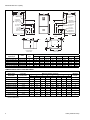
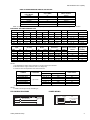
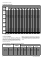
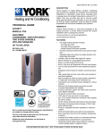
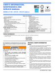
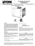
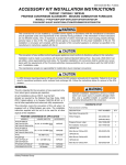
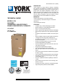
036-21560-001 Rev. A (0204)
R
Heating
Air Conditioning
DESCRIPTION
These Category IV, highly efficient, compact, condensing
type furnaces are designed for residential and commercial
installations in a basement, closet, alcove, recreation room or
garage where the ambient temperature is above 32°F, or
higher. They may be either side wall or thru-roof vented using
approved plastic type combustion air and vent piping. All
units are factory assembled, wired and tested to assure
dependable and economical installation and operation.
WARRANTY
TECHNICAL GUIDE
MODELS: GY9
GAS-FIRED
CONDENSING / HIGH EFFICIENCY
DOWNFLOW/HORIZONTAL FURNACES
91% AFUE
NATURAL GAS
60 - 120 MBH INPUT
Lifetime limited warranty on the heat exchanger.
10-year warranty on the heat exchanger in commercial
applications.
5-year limited parts warranty.
FEATURES
•
•
•
•
•
•
•
•
•
•
•
•
•
•
•
•
•
•
EFFICIENCY
RATING
CERTIFIED
•
•
Compact, easy to install, ideal height 40" cabinet
Blower-off delay for cooling SEER improvement.
Easy to connect power/control wiring.
Built-in, high level self diagnostics with fault code display.
Low unit amp requirement for easy replacement application.
Integrated control module for reliable, economical operation.
May be installed as either two-pipe (sealed combustion)
or single pipe vent (using indoor combustion air)
Top intake & vent connection allows downflow installation in narrow locations.
Electronic Hot Surface Ignition saves fuel cost with
increased dependability and reliability.
Induced combustion system with inshot main burners for
quiet, efficient operation.
No special vent termination kit required.
100% shut off main gas valve for extra safety.
PSC -four speed, direct drive motor with large, quiet
blower.
24V, 40 VA control transformer and blower relay supplied
for add-on cooling.
Hi-tech tubular aluminized steel primary heat exchanger.
Secondary (condensing) heat exchanger of 29-4C highgrade stainless steel.
Timed on, adjustable off blower capability for maximum
comfort.
Easy toolist access from front of unit for cleaning, maintenance or service.
Protection from intake, exhaust or condensate blockage.
High velocity filter provided for field installation.
This product was manufactured
in a plant whose quality system
is certified/registered as being
in conformity with ISO 9001.
FOR DISTRIBUTION USE ONLY - NOT TO BE USED AT POINT OF RETAIL SALE
036-21560-001 Rev. A (0204)
28-1/2
26-1/2
21-5/8
26-1/2
21-15/16
A
T’STAT WIRING
7/8” K.O.
T’STAT WIRING
7/8” K.O.
HORIZONTAL
CONDENSATE
DRAIN 2” K.O.
40
29
7/8” JUNCTION
BOX HOLE
7/8” JUNCTION
BOX HOLE
21-9/16
18-1/2
1-1/2” GAS
PIPE ENTRY
HORIZONTAL
CONDENSATE
DRAIN 2” K.O.
29
18-1/2
1-1/2” GAS
PIPE ENTRY
21-7/8
CONDENSATE
DRAIN 7/8” K.O.
11-11/16
7-1/2
CONDENSATE
DRAIN 7/8” K.O.
9-1/8
8-1/2
24-5/8
25-3/8
23-5/8
5/8
19-1/4
1-1/4
1-1/4
5/8
D
B
C
20
2-1/4
23-1/4
BOTTOM IMAGE
RETURN END
BTUH (kW)
Input/Output
CFM
Cabinet
Size
60/55 (17.57/16.10)
80/75 (23.42/21.96)
80/75 (23.42/21.96)
100/95 (29.28/27.82)
100/95 (29.28/27.82)
120/112 (35.14/32.80)
1200 (33.98)
1200 (33.98)
1600 (45.31)
1600 (45.31)
2000 (56.63)
2000 (56.63)
B
B
C
C
C
D
TOP IMAGE
SUPPLY END
Cabinet Dimension
A (in.)
17-1/2
17-1/2
21
21
21
24-1/2
A (cm)
44.4
44.4
53.3
53.3
53.3
62.2
B (in.)
16-1/4
16-1/4
19-3/4
19-3/4
19-3/4
23-1/4
B (cm)
41.3
41.3
50.2
50.2
50.2
59.1
C (in.)
15-1/8
15-1/8
18-1/2
18-1/2
18-1/2
21-7/8
C (cm)
38.4
38.4
47.0
47.0
47.0
55.6
D (in.)
1-3/4
1-3/4
2-1/8
2-1/8
2-1/8
2-1/2
D (cm)
4.44
4.44
5.40
5.40
5.40
6.35
COMBUSTION AIR SUPPLY AND VENT PIPING
MAXIMUM ELBOWS AND VENT LENGTHS
Models Input
BTUH (kW)
Pipe Size
Inches (mm)
60,000 (17.6)
1-1/2 (38)
60,000 (17.6)
2 (51)
Maximum Number of Elbows*
1
Minimum
Length
2
3
4
5
6
7
8
15
10
N/A
N/A
N/A
N/A
N/A
N/A
1.5
60
55
50
45
40
35
25
15
1.5
60,000 (17.6)
3 (76)
85
80
75
70
65
60
50
40
10
80,000 (23.4)/1200
2 (51)
60
55
50
45
40
35
25
15
1.5
80,000 (23.4)/1200
3 (76)
85
80
75
70
65
60
50
40
10
80,000 (23.4)/1600
2 (51)
25
20
15
10
N/A
N/A
N/A
N/A
1.5
80,000 (23.4)/1600
3 (76)
85
80
75
70
65
60
50
40
10
100,000 (29.3)
2 (51)
25
20
15
10
N/A
N/A
N/A
N/A
1.5
100,000 (29.3)
3 (76)
80
75
70
65
60
55
45
35
1.5
120,000 (35.1)
3 (76)
55
50
45
40
35
25
15
N/A
1.5
Three elbows (two in vent pipe and one in the air intake pipe) are already accounted for and need not be included in the elbow count
from the Table above.
2
Unitary Products Group
036-21560-001 Rev. A (0204)
HIGH ALTITUDE PRESSURE SWITCH APPLICATION
Input (MBH)
Upflow Models
Output (MBH)
4,500 To 10,000 Ft.
60/1200
80/1200
80/1600
100/1600
100/2000
120/2000
55
74
74
93
93
112
1PS0901
1PS0902
1PS0903
1PS0901
1PS0901
1PS0901
NOTE: For high altitude conversion, an orifice change may also be required. See Form 035-14460-001 for application information.
ELECTRICAL AND PERFORMANCE DATA
Input
Output
Nominal Airflow
MBH
kW
MBH
kW
CFM
60
80
80
100
100
120
18
23
23
29
29
35
55
74
74
93
93
112
16.1
21.7
21.7
27.3
27.3
32.8
1200
1200
1600
1600
2000
2000
Max. Outlet
Air Temp.
Input
MBH
60
80
80
100
100
120
kW
18
23
23
29
29
35
°F
170
170
170
175
175
175
°C
76.7
76.7
76.7
79.4
79.4
76.7
m3/min
34.0
34.0
45.3
45.3
56.6
56.6
Cabinet Width
%
°F
°C
17-1/2
17-1/2
21
21
21
24-1/2
444
444
533
533
533
622
91
91
91
91
91
91
40 - 70
35 - 65
40 - 70
35 - 65
35 - 65
35 - 65
22 - 39
19 - 36
22 - 39
19 - 36
19 - 36
19 - 36
Max.
Over-current
Protect
Min. Wire Size
(awg) @ 75 ft.
One Way
20
20
20
20
20
20
14
14
14
14
12
12
Blower Size
Amps
7.0
7.0
10.2
10.2
12.7
12.7
Air Temp. Rise
mm
Blower
HP
1/2
1/2
3/4
3/4
1
1
AFUE
In.
In.
11 x 8
11 x 8
11 x 10
11 x 10
11 x 11
11 x 11
Total Unit
mm
279 x 203
279 x 203
279 x 254
254 x 254
279 x 279
279 x 279
Amps
9
9
12
12
14
14
* Wire size and overcurrent protection must comply with the National Electric Code.
NOTES:
1. For altitudes above 2000 ft. reduce capacity 4% for each 1000 ft. above sea level.
2. Wire size based on copper conductors, 60°C, 3% voltage drop.
3. Continuous return air temperature must not be below 55°F.
MODEL
NUMBER
GY9S060B12DH11
GY9S080B12DH11
GY9S080C16DH11
GY9S100C16DH11
GY9S100C20DH11
GY9S120D20DH11
ADD-ON COOLING
TONS
CFM* @ .5 ESP
APPROX.
OPER. WEIGHT
1-1/2, 2, 2-1/2, 3
2, 2-1/2, 3
3, 3-1/2, 4
3, 3-1/2, 4
3-1/2, 4, 5
3-1/2, 4, 5
1550
1530
1860
1830
2000
2100
130
145
155
170
175
180
FILTER SIZE
(2) 14 x 20
* ESP (External Static Pressure) .5" WG is at furnace outlet ahead of cooling coil.
NOTES:
1. All filters must be high velocity cleanable type.
FIELD WIRING DIAGRAMS
BLK
POWER WIRING
BLK (HOT)
WHT
WHT (NEUTRAL)
GRN
GRD
Unitary Products Group
NOMINAL
115 VOLT
ROOM
THERMOSTAT
FURNACE
CONTROL
R
W
G
Y
C
R
W
G
Y
C
CONDENSING
UNIT
TO AIR CONDITIONER
CONTROLS
3
036-21560-001 Rev. A (0204)
BLOWER PERFORMANCE CFM
AIRFLOW WITH TOP RETURN
MODELS
EXTERNAL STATIC PRESSURE, INCHES W.C. (kPa)
Input/
Output/
Airflow/
cabinet
Speed
Tap
80/75/
1200/B
80/75/
1600/C
100/95/
1600/C
100/95/
2000/C
0.2 (0.050)
0.3 (0.075)
0.4 (0.099)
0.5 (0.124)
0.6 (0.149)
0.7 (0.174)
0.8 (0.199)
0.9 (0.224)
1.0 (0.249)
CFM m3/min CFM m3/min CFM m3/min CFM m3/min CFM m3/min CFM m3/min CFM m3/min CFM m3/min CFM m3/min CFM m3/min
High
60/55/
1200/B
0.1 (0.025)
1687
48
1652
47
1631
46
1595
45
1557
44
1511
43
1456
41
1382
39
1313
37
1211
34
Medium High 1193
34
1183
33
1173
33
1162
33
1142
32
1115
32
1076
30
1036
29
982
28
950
27
Medium Low 933
20
26
933
26
921
26
911
26
902
26
872
25
825
23
793
22
771
22
712
Low
752
21
745
21
731
21
718
20
698
20
652
18
602
17
580
16
536
15
496
14
High
1686
48
1658
47
1623
46
1572
44
1534
43
1465
41
1391
39
1305
37
1202
34
1091
31
Medium High 1257
36
1223
35
1218
34
1203
34
1177
33
1142
32
1094
31
1026
29
939
27
874
25
Medium Low 977
28
982
28
976
28
955
27
934
26
899
25
843
24
791
22
738
21
686
19
Low
775
22
777
22
757
21
733
21
698
20
663
19
627
18
584
17
549
16
490
14
High
2071
59
2026
57
1981
56
1935
55
1864
53
1796
51
1713
48
1625
46
1532
43
1401
40
Medium High 1583
45
1590
45
1569
44
1554
44
1532
43
1502
43
1457
41
1409
40
1327
38
1221
35
Medium Low 1256
36
1275
36
1275
36
1288
36
1275
36
1265
36
1232
35
1187
34
1126
32
1023
29
Low
937
27
939
27
936
26
945
27
942
27
936
26
912
26
874
25
810
23
726
21
High
1996
56
1961
56
1938
55
1896
54
1836
52
1779
50
1707
48
1625
46
1531
43
1399
40
Medium High 1449
41
1480
42
1495
42
1488
42
1488
42
1449
41
1417
40
1368
39
1299
37
1208
34
Medium Low 1167
33
1192
34
1192
34
1187
34
1202
34
1192
34
1182
33
1140
32
1097
31
1018
29
Low
932
26
900
25
871
25
840
24
805
23
761
22
710
20
663
19
641
18
623
18
High
2404
68
2320
66
2225
63
2138
61
2034
58
1924
54
1816
51
1692
48
1559
44
1422
40
Medium High 2018
57
1955
55
1883
53
1815
51
1750
50
1670
47
1586
45
1497
42
1394
39
1246
35
Medium Low 1626
27
46
1581
45
1531
43
1488
42
1418
40
1363
39
1291
37
1225
35
1123
32
964
Low
1336
38
1291
37
1249
35
1205
34
1155
33
1091
31
1018
29
951
27
884
25
759
21
High
2520
71
2432
69
2353
67
2251
64
2152
61
2042
58
1947
55
1815
51
1701
48
1525
43
120/112/ Medium High 2018
2000/D Medium Low 1586
57
1979
56
1945
55
1911
54
1863
53
1779
50
1705
48
1599
45
1493
42
1353
38
45
1545
44
1501
42
1457
41
1407
40
1351
38
1287
36
1216
34
1081
31
926
26
37
1266
36
1213
34
1163
33
1111
31
1071
30
987
28
864
24
763
22
700
20
Low
1321
1. Airflow expressed in standard cubic feet per minute (CFM) and in cubic meters per minute (m3/min).
2. Motor voltage at 115 V.
FILTER PERFORMANCE
The airflow capacity data published in the “Blower Performance” table listed above represents blower performance
WITHOUT filters. To determine the approximate blower performance of the system, apply the filter drop value for the filter being used or select an appropriate value from the “Filter
Performance” table shown.
NOTE: The filter pressure drop values in the “Filter Performance” table shown are typical values for the type of filter
listed and should only be used as a guideline. Actual pressure drop ratings for each filter type vary between filter manufacturer.
FILTER PERFORMANCE - PRESSURE DROP INCHES W.C. AND (KPA)
FILTER TYPE
AIRFLOW RANGE
*.
4
MINIMUM
OPENING SIZE
DISPOSABLE
COARSE FIBER
WASHABLE**
PLEATED
CFM
m3/m
in2
cm2
In W.C.
kPA
In W.C.
kPA
In W.C..
kPA
0 - 750
0 - 21.4
230
584.2
0.01
0.00249
0.01
0.00249
0.15
0.03736
751 - 1000
21.25 - 28.32
330
838.2
0.05
0.01245
0.05
0.01245
0.20
0.04982
1001 - 1250
28.33 - 35.40
330
838.2
0.10
0.02491
0.10
0.02491
0.20
0.04982
1251 - 1500
35.41 - 42.48
330
838.2
0.10
0.02491
0.10
0.02491
0.25
0.06227
1501 - 1750
42.49 - 49.55
380
965.2
0.15
0.03736
0.14
0.03487
0.30
0.07473
1751 - 2000
49.56 - 56.63
380
965.2
0.19
0.04733
0.18
0.04484
0.30
0.07473
2001 & Above
56.64 - Above
463
1176.0
0.19
0.04733
0.18
0.04484
0.30
0.07473
Coarse Fiber Filters are the type supplied with furnace (if supplied).
Unitary Products Group
036-21560-001 Rev. A (0204)
APPLYING FILTER PRESSURE DROP TO
DETERMINE SYSTEM AIRFLOW
Example: For a 130,000 Btuh furnace operating on high
speed blower, it is found that total system static is 0.58" w.c.
To determine the system airflow, complete the following
steps:
To determine the approximate airflow of the unit with a filter in
place, follow the steps below:
1.
1.
Select the filter type.
2.
Determine the External System Static Pressure (ESP)
without the filter.
3.
Select a filter pressure drop from the table based upon
the number of return air openings or return air opening
size and add to the ESP from Step 3 to determine the
total system static.
4.
5.
Obtain the airflow values at 0.50" & 0.60" ESP.
Airflow @ 0.50": 2125 CFM
Airflow @ 0.60": 2035 CFM
2.
Subtract the airflow @ 0.50" from the airflow @ 0.60" to
obtain airflow difference.
2035 - 2125 = -90 CFM
3.
If total system static matches a ESP value in the airflow
table (i.e. 0.20, 0.60, etc,) the system airflow corresponds to the intersection of the ESP column and Model/
Blower Speed row.
Subtract the total system static from 0.50" and divide this
difference by the difference in ESP values in the table,
0.60" - 0.50", to obtain a percentage.
(0.58 - 0.50) / (0.60 - 0.50) = 0.8
4.
If the total system static falls between ESP values in the
table (i.e. 0.58, 0.75, etc.), the static pressure may be
rounded to the nearest value in the table determining the
airflow using Step 5 or calculate the airflow by using the
following example.
Multiply percentage by airflow difference to obtain airflow
reduction.
(0.8) x (-90) = -72
5.
Subract airflow reduction value to airflow @ 0.50" to
obtain actual airflow @ 0.58" ESP.
2125 - 72 = 2053
UNIT CLEARANCES TO COMBUSTIBLES
APPLICATION
TOP
FRONT
REAR
LEFT
SIDE
RIGHT
SIDE
FLUE
FLOOR/
BOTTOM
CLOSET
ALCOVE
ATTIC
LINE
CONTACT
DOWNFLOW
1
3
0
0
0
0
1"*
YES
YES
YES
NO
HORIZONTAL
0
3
0
1
1
0
COMBUSTIBLE
NO
YES
YES
YES†
*. Special floor base or air conditioning coil required for use on combustible floor.
†. Line contact only permitted between lines formed by the intersection of the rear panel and side panel (top in horizontal position) of
the furnace jacket and building joists, studs or framing.
ACCESSORIES
PROPANE (LP) CONVERSION KIT 1NP0347 - All units
This accessory conversion kit may be used to convert natural
gas (N) units for propane (LP) operation. Conversions must
be made by qualified distributor or dealer personnel.
CONCENTRIC VENT TERMINATION 1CT0302 (2")
1CT0303 (3")
For use through rooftop, sidewall. Allows combustion air to
enter and exhaust to exit through single common hole. Eliminates unslightly elbows for a cleaner installation.
Unitary Products Group
COIL TRANSITION KIT 1TK0917 - 17” Furnace
1TK0921 - 21” Furnace
1TK0924 - 24” Furnace
Required in downflow applications when using G*FD series
coils.
CONDENSATE NEUTRALIZER KIT - 1NK0301
Neutralizer cartidge has a 1/2" plastic tube fittings for installation in the drain line. Calcium carbonate refill media is also
avaiable from the Source 1 Parts (p/n 026-30228-000).
HIGH ALTITUDE PRESSURE SWITCHES Used to convert units for operation at altitudes from 4,500 ft.
to 10,000 ft. Refer to table on page 3 for proper pressure
switch application. For Application See 035-14447-000.
5
036-21560-001 Rev. A (0204)
FIELD INSTALLED ACCESSORIES - ELECTRICAL
6
MODEL NO.
DESCRIPTION
2ET03700324
THERMOSTAT- Electronic Non-Programmable.
One-stage Heat/Cool. Manual Changeover, Integral Subbase.
System Switch: Cool-Off-Heat. Fan Switch: Auto-On.
2TH13700424
THERMOSTAT- One-stage Heat. Deluxe 24V with Heat only Subbase, does not include Fan Switch. NOTE: For One-stage Cool or
One-stage Heat/Cool, must be used with Subbase 2TB17700424.
2TB17700424
SUBBASE (24V) - One-stage heat/cool. Manual changeover, integral
subbase. System Switch: Cool-Off-Heat. Fan Switch: Auto-On.
2ET03701024
THERMOSTAT- Electronic 7 Day Programmable.
One Heat/One Cool. Auto Changeover, Integral Subbase.
System Switch: Cool-Off-Heat. Fan Switch: Auto-On. Power Stealing
2ET03700024
(TS) THERMOSTAT- Electronic 7 Day Programmable.
Two Heat/Two Cool. Auto Changeover, Integral Sub-base.
System Switch: Cool-Off-Heat. Fan Switch: Auto-On.
Unitary Products Group
036-21560-001 Rev. A (0204)
NOTES
Unitary Products Group
7
Subject to change without notice. Printed in U.S.A.
Copyright © by York International Corp. 2004. All rights reserved.
Unitary
Products
Group
036-21560-001 Rev. A (0204)
Supersedes: Nothing
5005
York
Drive
Norman
OK
73069