1
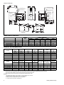
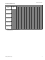
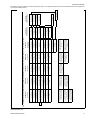
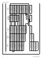
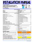
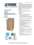
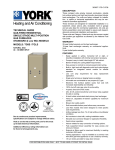
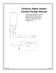
246782-YTG-B-0407
DESCRIPTION
These Category IV, highly efficient, compact, condensing
type furnaces are designed for residential and commercial
installations in a basement, closet, alcove, recreation room or
garage where the ambient temperature is above 32°F, or
higher. They may be either side wall or thru-roof vented using
approved plastic type combustion air and vent piping. All
units are factory assembled, wired and tested to assure
dependable and economical installation and operation.
TECHNICAL GUIDE
WARRANTY
AFFINITY
MODELS: PT9
Lifetime limited warranty on both heat exchangers to the original purchaser; a 20-year limited warranty from original installation date to subsequent purchaser.
GAS-FIRED
CONDENSING / HIGH EFFICIENCY
DOWNFLOW/HORIZONTAL
TWO STAGE FURNACES
10-year warranty on commercial applications.
NATURAL GAS
60 - 120 MBH INPUT
EFFICIENCY
RATING
CERTIFIED
ISO 9001
Certified Quality
Management System
Due to continuous product improvement,
specifications are subject to change without notice.
Visit us on the web at www.york.com for the most
up-to-date technical information.
Additional rating information can be found at
www.gamanet.org.
5-year limited parts warranty.
FEATURES
• Two stage heating operation includes:
- Two stage gas valve
- Two stage inducer operation
• Provides increased comfort level & very quiet unit operation.
• Adjustable delay timer allows two stage operation with single stage thermostat.
• Compact, easy to install, ideal height 40" cabinet.
• Blower-off delay for cooling SEER improvement.
• Easy to connect power/control wiring.
• Built-in, high level self diagnostics with fault code display.
• Low unit amp requirement for easy replacement application.
• Integrated control module for reliable, economical operation.
• May be installed as either two-pipe (sealed combustion) or
single pipe vent (using indoor combustion air).
• Top intake & vent connection allows installation in narrow
locations.
• Electronic Hot Surface Ignition saves fuel cost with
increased dependability and reliability.
• Induced combustion system with inshot main burners for
quiet, efficient operation.
• No special vent termination kit required.
• 100% shut off main gas valve for extra safety.
• PSC - four speed, direct drive motor with large, quiet
blower.
• 24V, 40 VA control transformer and blower relay supplied
for add-on cooling.
• Hi-tech tubular aluminized steel primary heat exchanger.
• Secondary (condensing) heat exchanger of 29-4C highgrade stainless steel.
• Timed on, adjustable off blower capability for maximum
comfort.
• Independent door removal for greater durabilty and ease
of access.
• Easy access from front of unit for cleaning, maintenance or
service.
• Protection from intake, exhaust or condensate blockage.
• Insulated blower compartment for quiet operation.
• 3-way transition facilitates fresh air piping.
FOR DISTRIBUTION USE ONLY - NOT TO BE USED AT POINT OF RETAIL SALE
246782-YTG-B-0407
22-3/4
A
7/8
T-STAT WIRING 7/8” K.O.
7/8
T-STAT WIRING 7/8” K.O.
HORIZONTAL CONDENSATE
DRAIN OPENING 1-3/4”
13-7/8
HORIZONTAL CONDENSATE
DRAIN OPENING 1-3/4”
40
HORIZONTAL CONDENSATE
DRAIN OPENING 2”
JUNCTION BOX
HOLE 7/8”
22-3/4
GAS PIPE ENTRY 1-1/2”
HORIZONTAL
CONDENSATE
DRAIN OPENING 1-3/4”
29
29
CONDENSATE DRAIN
HOLE 7/8”
JUNCTION BOX
HOLE 7/8”
22-3/4
21-5/8
21-1/4
18-1/2
18-1/2
11-3/4
7-1/2
SIDE PIPING HOLE 3-3/8”
GAS PIPE
ENTRY 1-1/2”
9-1/8
8-1/2
CONDENSATE DRAIN
HOLE 7/8”
2-1/4
22-1/4
25-3/8
26-1/2
27-1/8
30-1/8
FRONT
23-11/16
23-5/8
1-1/4
19-1/4
LEFT SIDE
RIGHT SIDE
5/8
1-1/4
E
5/8
D
B
C
20
2-1/4
23-1/4
BOTTOM IMAGE
SUPPLY END
TOP IMAGE
RETURN END
CABINET AND DUCT DIMENSIONS
CABINET DIMENSION
Models
CFM
CABINET
SIZE
A (IN.)
B (IN.)
C (IN.)
D (IN.)
E (IN.)
PT9B12N060DH11
1200
B
17-1/2
16-1/4
15
1-3/4
2-3/8
PT9B12N080DH11
1200
B
17-1/2
16-1/4
15
1-3/4
2-3/8
PT9C16N080DH11
1600
C
21
19-3/4
18-1/2
2-1/8
2-3/4
PT9C20N100DH11
2000
C
21
19-3/4
18-1/2
2-1/8
2-3/4
PT9D20N120DH11
2000
D
24-1/2
23-1/4
22
2-1/2
3
ELECTRICAL AND PERFORMANCE DATA
Models
Input
(High/Low)
Output
(High/Low)
MBH
MBH
PT9B12N060DH11
60 / 39
56 / 36
Nominal
Airflow
Air Temp.
Rise
Cabinet
Width
Total Unit
CFM
In.
Amps
%
°F
1200
17-1/2
9
92
35 - 65
35 - 65
AFUE
PT9B12N080DH11
80 / 52
75 / 49
1200
17-1/2
9
92
PT9C16N080DH11
80 / 52
75 / 49
1600
21
12
92
35 - 65
PT9C20N100DH11
100 / 65
93 / 61
2000
21
14
92
35 - 65
PT9D20N120DH11
120 / 78
112 / 74
2000
24-1/2
14
92
35 - 65
Models
Input
(High/Low)
Max. Outlet
Air Temp.
Blower
Blower
Size
°F
HP
Amps
In.
Min. Wire Size
(awg) @ 75 ft.
One Way
Operating
Weight
MBH
Max.
Over-current
Protect
PT9B12N060DH11
60 / 39
165
1/2
7.0
11 x 8
20
14
136
PT9B12N080DH11
80 / 52
165
1/2
7.0
11 x 8
20
14
143
PT9C16N080DH11
80 / 52
165
3/4
10.2
11 x 10
20
14
159
PT9C20N100DH11
100 / 65
165
1
12.7
11 x 11
20
12
164
PT9D20N120DH11
120 / 78
165
1
12.7
11 x 11
20
12
182
Lbs.
Annual Fuel Utilization Efficiency (AFUE) numbers are determined in accordance with DOE Test procedures.
Wire size and over current protection must comply with the National Electrical Code (NFPA-70-latest edition) and all local codes.
The furnace shall be installed so that the electrical components are protected from water.
* Wire size and overcurrent protection must comply with the National Electric Code.
NOTES:
1. For altitudes above 2000 ft. reduce capacity 4% for each 1000 ft. above sea level.
2. Wire size based on copper conductors, 60°C, 3% voltage drop.
3. Continuous return air temperature must not be below 55°F.
4. All filters must be high velocity cleanable type.
2
Unitary Products Group
246782-YTG-B-0407
BLOWER PERFORMANCE CFM
AIRFLOW WITH TOP RETURN - WITHOUT FILTERS
EXTERNAL STATIC PRESSURE, INCHES W.C.
Speed
Tap
0.1
CFM
CFM
CFM
High
1687
1652
1631
Medium High
1193
1183
1173
Medium Low
933
933
921
Models
PT9B12N060DH11
PT9B12N080DH11
PT9C16N080DH11
PT9C20N100DH11
PT9D20N120DH11
0.2
0.3
0.4
0.5
0.6
0.7
0.8
0.9
1.0
CFM
CFM
CFM
CFM
1595
1557
1511
1456
CFM
CFM
CFM
1382
1313
1162
1142
1115
1076
1036
982
1211
950
911
902
872
825
793
771
712
Low
752
745
731
718
698
652
602
580
536
496
High
1686
1658
1623
1572
1534
1465
1391
1305
1202
1091
Medium High
1257
1223
1218
1203
1177
1142
1094
1026
939
874
Medium Low
977
982
976
955
934
899
843
791
738
686
Low
775
777
757
733
698
663
627
584
549
490
High
2071
2026
1981
1935
1864
1796
1713
1625
1532
1401
Medium High
1583
1590
1569
1554
1532
1502
1457
1409
1327
1221
Medium Low
1256
1275
1275
1288
1275
1265
1232
1187
1126
1023
Low
937
939
936
945
942
936
912
874
810
726
High
2404
2320
2225
2138
2034
1924
1816
1692
1559
1422
Medium High
2018
1955
1883
1815
1750
1670
1586
1497
1394
1246
Medium Low
1626
1581
1531
1488
1418
1363
1291
1225
1123
964
Low
1336
1291
1249
1205
1155
1091
1018
951
884
759
High
2520
2432
2353
2251
2152
2042
1947
1815
1701
1525
Medium High
2018
1979
1945
1911
1863
1779
1705
1599
1493
1353
Medium Low
1586
1545
1501
1457
1407
1351
1287
1216
1081
926
Low
1321
1266
1213
1163
1111
1071
987
864
763
700
NOTES:
1. Airflow expressed in standard cubic feet per minute.
2. Motor voltage at 115 V.
Unitary Products Group
3
246782-YTG-B-0407
FILTER PERFORMANCE
The airflow capacity data published in the “Blower Performance” table listed above represents blower performance
WITHOUT filters. To determine the approximate blower performance of the system, apply the filter drop value for the filter being used or select an appropriate value from the “Filter
Performance” table shown.
NOTE: The filter pressure drop values in the “Filter Performance” table shown are typical values for the type of filter
listed and should only be used as a guideline. Actual pressure drop ratings for each filter type vary between filter manufacturer.
RECOMMENDED FILTER SIZES
CFM
Cabinet
Size
Top Return
Filter in
60
1200
B
(2) 14 x 20
80
1200
B
(2) 14 x 20
80
1600
C
(2) 14 x 20
100
2000
C
(2) 14 x 20
120
2000
D
(2) 14 x 20
Input
BTU/H
APPLYING FILTER PRESSURE DROP TO
DETERMINE SYSTEM AIRFLOW
To determine the approximate airflow of the unit with a filter in
place, follow the steps below:
Select the filter type.
2.
Determine the External System Static Pressure (ESP)
without the filter.
Select a filter pressure drop from the table based upon
the number of return air openings or return air opening
size and add to the ESP from Step 3 to determine the
total system static.
4.
If total system static matches a ESP value in the airflow
table (i.e. 0.20, 0.60, etc,) the system airflow corresponds to the intersection of the ESP column and Model/
Blower Speed row.
5.
If the total system static falls between ESP values in the
table (i.e. 0.58, 0.75, etc.), the static pressure may be
rounded to the nearest value in the table determining the
airflow using Step 5 or calculate the airflow by using the
following example.
Example: For a 120,000 Btuh furnace operating on high
speed blower, it is found that total system static is 0.58" w.c.
To determine the system airflow, complete the following
steps:
1. Obtain the airflow values at 0.50" & 0.60" ESP.
Airflow @ 0.50": 2152CFM
Airflow @ 0.60": 2042 CFM
2. Subtract the airflow @ 0.50" from the airflow @ 0.60" to
obtain airflow difference.
2042 - 2152 = -110 CFM
Subtract the total system static from 0.50" and divide this
difference by the difference in ESP values in the table, 0.60" 0.50", to obtain a percentage.
(0.58 - 0.50) / (0.60 - 0.50) = 0.8
3. Multiply percentage by airflow difference to obtain airflow
reduction.
(0.8) x (-110) = -88
4. Subtract airflow reduction value to airflow @ 0.50" to
obtain actual airflow @ 0.58" ESP.
2152 - 88 = 2064
NOTES:
1. Air velocity through throwaway type filters may not exceed 300
feet per minute. All velocities over this require the use of high
velocity filters.
1.
3.
FILTER PERFORMANCE - PRESSURE DROP INCHES W.C.
Filter Type
Airflow Range
Minimum
Opening Size
Disposable
Washable Fibers
Pleated
CFM
in2
In W.C.
In W.C.
In W.C.
0 - 750
230
0.01
0.01
0.15
751 - 1000
330
0.05
0.05
0.20
1001 - 1250
330
0.10
0.10
0.20
1251 - 1500
330
0.10
0.10
0.25
1501 - 1750
380
0.15
0.14
0.30
1751 - 2000
380
0.19
0.18
0.30
2001 & Above
463
0.19
0.18
0.30
UNIT CLEARANCES TO COMBUSTIBLES
Top
Front
Rear
Left Side
Right Side
Flue
Floor/Bottom
In.
In.
In.
In.
In.
In.
In.
Downflow
1
3
0
0
0
0
Horizontal
0
3
0
1
1
0
1*
0
Application
*
4
Closet
Alcove
Attic
Line
Contact
Yes
Yes
Yes
NA
Yes
Yes
Yes
Yes2
Combustible floor base or air conditioning coil required for use on combustible floor.
Unitary Products Group
Unitary Products Group
Thermostat Installer Setup
Number 0170 - System Type must be set to 8 - 2 Heat/2 Cool
Multistage Conventional
Thermostat Installer Setup
Number 1 - System Type must be set to 6 2 Heat/2 Cool Conventional
Thermostat Installer Setup
Number 15 - Compressor
Protection - must be set to 5
Connection of the "C" Termainal,
24-Volt Common, is optional
when used with batteries
Connection of the "C" Termainal,
24-Volt Common, is optional
when used with batteries
Step 1 of Thermostat User
Configuration Menu must be
set to MS 2
Connection of the "C"
Termainal, 24-Volt Common,
is optional when used with
batteries
G
Fan
G
Fan
Connection of the "C"
Termainal, 24-Volt Common,
is optional when used with
batteries
W2
Second Stage Heat
W2
Second Stage Heat
G
Fan
E/W1
First Stage Heat
E/W1
First Stage Heat
G
Fan
RC
24-Volt Hot (Cool XFMR)
RC
24-Volt Hot (Cool XFMR)
R
24-Volt Hot
W2
Second Stage Heat
R
24-Volt Hot
R
24-Volt Hot (Heat XFMR)
R
24-Volt Hot (Heat XFMR)
Y2
Second Stage Cool
W2
Second Stage Heat
Y2
Second Stage Cool
Y2
Second Stage Cool
Y2
Second Stage Cool
Y1
First Stage Cool
E/W1
First Stage Heat
Y
First Stage Cool
Y
First Stage Cool
Y
First Stage Cool
C
24-Volt Common
W
First Stage Heat
C
24-Volt Common
C
24-Volt Common
Step 16 of Thermostat User
Configuration Menu must be set
to ON to use Comfort Alert
Features
Step 1 of Thermostat User
Configuration Menu must be set
to MLTI STG
HM
Humidistat
L
Malfunction Light
G
Fan
W2
Second Stage Heat
E/W1
First Stage Heat
R
24-Volt Hot
Y2
Second Stage Cool
Y1
First Stage Cool
C
24-Volt Common
*PP32U72124
*PP32U71124
*DP22U70124
C
24-Volt Common
THERMOSTAT
THERMOSTAT
*PP32U70124
*DN22U00124
*DN22C00124
THERMOSTAT
THERMOSTAT
THERMOSTAT
AC9 2 Stage Scroll A/C w/2 Stage Furnace, 2 Stage Cooling Ready- PT8/9; (F,L)*8/9T, (G,L)*8/9T, XYG8S-*, XYF8S-*, XYG9S-*, XYF9S-*
G
Fan
W2
Second Stage Heat
W/W1
Single/First Stage Heat
Y1
First Stage Cool
Y/Y2
Single/Second Stage
Cool
R
24-Volt Hot
C
24-Volt Common
2 STAGE PSC
FURNACE CONTROL
24V HUMIDIFIER
(Optional)
Comfort Alert
Interface
R
24-Volt Hot
Y2
Second Stage Cool
Y1
First Stage Cool
C
24-Volt Common
TWO STAGE
AIR CONDITIONING
For additional connection diagrams for all UPG equipment refer to “Low Voltage System Wiring” document available online at www.upgnet.com
in the Product Catalog Section.
246782-YTG-B-0407
Thermostat Chart - AC
5
HP23
6
Thermostat Installer Setup Number 0210 External Fossil Fuel Kit - must be set to 0 External Fossil Fuel Kit is Controlling
Heat Pump Backup Heat
Thermostat Installer Setup Number 0200
- Backup Heat Source - must be set to 1 - Heat
Pump Backup Heat Source is Fossil Fuel
Step 1 of Thermostat User
Configuration Menu must be
set to Heat Pump 2
W2
Second Stage Auxiliary Heat
Thermostat Installer Setup Number 0190 Reversing Valve (O/B) Operation - must be set to 0
- O/B Terminal Energized in Cooling
E/W1
First Stage Auxiliary Heat
AUX
Auxiliary Heat
Selection of GAS/ELEC switch on
thermostat not necessary
W2
Second Stage Auxiliary Heat
Y2
Second Stage Heat/Cool
Y2
Second Stage Heat/Cool
Thermostat Installer Setup Number 0170
- System Type - must be set to
12 - 3 Heat/2 Cool Heat Pump
E/W1
First Stage Auxiliary Heat
L
Malfunction Light
L
Malfunction Light
Step 1 of Thermostat User Configuration
Menu must be set to Heat Pump 2
HM
Humidistat
Y2
Second Stage Heat/Cool
L
Malfunction Light
O
Reversing Valve–Energized in Cool
O
Reversing Valve–Energized in Cool
O/B
Reversing Valve
G
Fan
G
Fan
DHM
Dehumidistat
G
Fan
E
Emergency Heat
R
24-Volt Hot
Y1
First Stage Heat/Cool
Y1
First Stage Cool
C
24-Volt Common
Set W2 Delay on furnace to OFF
24V HUMIDIFIER
(Optional)
Bonnet Sensor
(Optional)
G
Fan
W2
Second Stage Heat
W/W1
Single/First Stage Heat
R
24-Volt Hot
R
24-Volt Hot
Y1
First Stage Heat/Cool
Y
First Stage Heat/Cool
C
24-Volt Common
*PP32U72124
PSC-2 STAGE
COOLING READY
FURNACE CONTROL
R
24-Volt Hot (Heat XFMR)
C
24-Volt Common
C
24-Volt Common
*PP32U71124
THERMOSTAT
Y/Y2
Single/Second Stage Cool
*DN22H00124
*DP22U70124
*PP32U70124
RC
24-Volt Hot (Cool XFMR)
THERMOSTAT
THERMOSTAT
Two Stage H/P - H*5B, YZE - w/Two Stage Furnace, 2 Stage Cooling Ready - PT8/9, (F,L)*8/9T, (G,L)*8/9T, XYG8S-*, XYF8S-*, XYG9S-*, XYF9S-*
W/031-01996- Series Demand Control; Hot Heat Pump Mode OR Conventional
Change FFuel Jumper on
Heat Pump to ON
BS
Bonnet Sensor
BSG
Bonnet Sensor
W
Auxiliary Heat
Y2
Second Stage Heat/Cool
X/L
Malfunction Light
O
Reversing Valve–Energized in Cool
W2 OUT
Second Stage Auxiliary Heat Output
W1 OUT
First Stage Auxiliary Heat Output
R
24-Volt Hot
Y2 OUT
Second Stage Cool Output
Y1
First Stage Heat/Cool
C
24-Volt Common
TWO STAGE
HEAT PUMP
246782-YTG-B-0407
Thermostat Chart - HP
Unitary Products Group
246782-YTG-B-0407
ACCESSORIES
PROPANE (LP) CONVERSION KIT 1NP0347 - All units
This accessory conversion kit may be used to convert natural
gas units for propane (LP) operation. Conversions must be
made by qualified distributor or dealer personnel.
CONCENTRIC VENT TERMINATION 1CT0302 (2")
1CT0303 (3")
For use through rooftop, sidewall. Allows combustion air to
enter and exhaust to exit through single common hole. Eliminates unslightly elbows for a cleaner installation.
SIDEWALL VENT TERMINATION KIT 1HT0901 (3")
1HT0902 (2")
For use on sidewall, two-pipe installations only. Provide a
more attractive termination for locations where the terminal is
visable on the side of the home.
COMBUSTIBLE FLOOR BASE 1CB0317 - 17 1/2” Cabinet
1CB0321 - 21” Cabinet
1CB0324 - 24-1/2” Cabinet
COIL TRANSITION KIT 1TK0917 - 17-1/2” Furnace
1TK0921 - 21” Furnace
1TK0924 - 24-1/2” Furnace
These kits are required in downflow application when using
G*F* series coils. These kits are not required with MC/FC
series coils, but please ensure that the coil and furnace are
secured and that there are no air leaks.
Unitary Products Group
CONDENSATE NEUTRALIZER KIT - 1NK0301
Neutralizer cartidge has a 1/2" plastic tube fittings for installation in the drain line. Calcium carbonate refill media is also
avaiable from the Source 1 Parts (p/n 026-30228-000).
HIGH ALTITUDE PRESSURE SWITCHES For installation where the altitude is less than 8,000 feet it is
not required that the pressure switch be changed. For altitudes above 8,000 feet see kits below. Conversion must be
made by qualified distributor or dealer personnel.
1PS0507 - 060 MBH
1PS0508 - 080/1200 MBH
1PS0509 - 080/1600 MBH
1PS0510 - 100 MBH
1PS0511 - 120 MBH
ROOM THERMOSTATS - A wide selection of compatible
thermosets are available to provide optimum performance
and features for any installation.
1H/1C, manual change-over electronic non-programmable
thermostat.
1H/1C, auto/manual changeover, electronic programmable,
deluxe 7-day, thermostat.
1H/1C, auto/manual changeover, electronic programmable.
* For the most current accessory information, refer to the
price book or consult factory.
7
Subject to change without notice. Printed in U.S.A.
Copyright © by York International Corp. 2007. All rights reserved.
Unitary
Products
Group
246782-YTG-B-0407
Supersedes: 246782/035-21633-002 Rev. A (1205)
5005
York
Drive
Norman
OK
73069