1
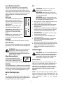
Operator’s Manual
Two-Stage
Snow Thrower
Model 5KL
IMPORTANT: Read safety rules and instructions carefully before operating equipment.
Warning: This unit is equipped with an internal combustion engine and should not be used on or near any unimproved forestcovered, brush-covered or grass-covered land unless the engine’s exhaust system is equipped with a spark arrester meeting
applicable local or state laws (if any). If a spark arrester is used, it should be maintained in effective working order by the operator.
In the State of California the above is required by law (Section 4442 of the California Public Resources Code). Other states may have
similar laws. Federal laws apply on federal lands. A spark arrester for the muffler is available through your nearest engine authorized
service dealer or contact the service department, P.O. Box 361131 Cleveland, Ohio 44136-0019.
MTD LLC, P.O. BOX 361131 CLEVELAND, OHIO 44136-0019
Printed in U.S.A.
FORM NO. 770-10028G.fm
(7/2004)
TABLE OF CONTENTS
Content
Customer Support
Important Safe Operation Practices
Setting Up Your Snow Thrower
Operating Your Snow Thrower
Maintaining Your Snow Thrower
Content
Service & Adjustments
Off-Season Storage
Troubleshooting
Illustrated Parts List
Warranty
Page
2
3
5
8
12
Page
14
18
19
20
Back Cover
FINDING MODEL NUMBER
This Operator’s Manual is an important part of your new snow thrower. It will help you assemble, prepare
and maintain the unit for best performance. Please read and understand what it says.
Before you start assembling your new equipment, please locate the model plate on the
equipment and copy the information from it in the space provided below. You can locate the
model plate by standing at the operating position and looking down at the rear of the snow
thrower. A sample model plate is also given below. This information will be necessary to use the
manufacturer’s web site and/or help from the Customer Support Department or an authorized
service dealer.
Copy the model number here:
Copy the serial number here:
www.yardman.com
MTD LLC
P. O. BOX 361131
CLEVELAND,OH 44136
330-220-4683
800-800-7310
CUSTOMER SUPPORT
Please do NOT return the unit to the retailer from where it was purchased, without first contacting Customer Support.
If you have difficulty assembling this product or have any questions regarding the controls, operation or
maintenance of this unit, you can seek help from the experts. Choose from the options below:
Visit yardman.com for many useful suggestions. Click on Customer Support button and you
will get the four options reproduced here. Click on the appropriate button and help is
immediately available.
The answer you are
looking for could be just
a mouse click away!
The answer you are
looking for could be just
a mouse click away!
To reach the Customer Support Line, please call 1-800-800-7310.
Engine
Manual
The engine manufacturer is responsible for all engine-related issues with regards to
performance, power-rating, specifications, warranty and service. Please refer to the engine
manufacturer’s Owner’s/Operator’s Manual, packed separately with your unit, for more
information.
2
SECTION 1: IMPORTANT SAFE OPERATIONS PRACTICES
WARNING: This symbol points out important safety instructions which, if not followed, could endanger
the personal safety and/or property of yourself and others. Read and follow all instructions in this manual
before attempting to operate this machine. Failure to comply with these instructions may result in personal
injury. When you see this symbol—heed its warning.
WARNING: Engine Exhaust, some of its constituents, and certain vehicle components contain or emit
chemicals known to State of California to cause cancer and birth defects or other reproductive harm.
DANGER: This machine was built to be operated according to the rules for safe operation in this manual. As with
any type of power equipment, carelessness or error on the part of the operator can result in serious injury. This
machine is capable of amputating hands and feet and throwing objects. Failure to observe the following safety
instructions could result in serious injury or death.
Training
4. Use a grounded three-wire extension cord and
receptacle for all units with electric start engines.
5. Adjust collector housing height to clear gravel or
crushed rock surfaces.
6. Disengage all controls before starting the engine.
7. Never attempt to make any adjustments while
engine is running, except where specifically
recommended in the operator’s manual.
8. Let engine and machine adjust to outdoor
temperature before starting to clear snow.
9. To avoid personal injury or property damage use
extreme care in handling gasoline. Gasoline is
extremely flammable and the vapors are explosive.
Serious personal injury can occur when gasoline is
spilled on yourself or your clothes, which can ignite.
Wash your skin and change clothes immediately.
a. Use only an approved gasoline container.
b. Extinguish all cigarettes, cigars, pipes and
other sources of ignition.
c. Never fuel machine indoors.
d. Never remove gas cap or add fuel while the
engine is hot or running.
e. Allow engine to cool at least two minutes
before refueling.
f. Never over fill fuel tank. Fill tank to no more
than ½ inch below bottom of filler neck to
provide space for fuel expansion.
g. Replace gasoline cap and tighten securely.
h. If gasoline is spilled, wipe it off the engine
and equipment. Move machine to another
area. Wait 5 minutes before starting the
engine.
i. Never store the machine or fuel container
inside where there is an open flame, spark or
pilot light (e.g. furnace, water heater, space
heater, clothes dryer etc.).
j. Allow unit to cool for 5 minutes before
storing.
1. Read, understand, and follow all instructions on the
machine and in the manual(s) before attempting to
assemble and operate. Keep this manual in a safe
place for future and regular reference and for
ordering replacement parts.
2. Be familiar with all controls and their operation.
Know how to stop the machine and disengage
controls.
3. Never allow children under 14 years old to operate
this machine. Children 14 years old and over
should read and understand the operation
instructions and safety rules in this manual and
should be trained and supervised by a parent.
4. Never allow adults to operate this machine without
proper instruction.
5. Thrown objects can cause serious personal injury.
Plan your snow-throwing pattern to avoid discharge
of material toward roads, bystanders and the like.
6. Keep bystanders, helpers, pets and children at
least 75 feet from the machine while it is in
operation. Stop machine if anyone enters the area.
7. Exercise caution to avoid slipping or falling,
especially when operating in reverse.
Preparation
1. Thoroughly inspect the area where the equipment
is to be used. Remove all doormats, newspapers,
sleds, boards, wires and other foreign objects,
which could be tripped over or thrown by the auger/
impeller.
2. Always wear safety glasses or eye shields during
operation and while performing an adjustment or
repair to protect your eyes. Thrown objects which
ricochet can cause serious injury to the eyes.
3. Do not operate without wearing adequate winter
outer garments. Do not wear jewelry, long scarves
or other loose clothing, which could become
entangled in moving parts. Wear footwear which
will improve footing on slippery surfaces.
3
Operation
unclogging, shut off engine and remain behind
handles until all moving parts have stopped
completely.
19. Use only attachments and accessories approved
by the manufacturer (e.g. wheel weights, tire
chains, cabs etc.).
20. If situations occur which are not covered in this
manual, use care and good judgment. Contact your
dealer or telephone 1-800-800-7310 for assistance
and the name of your nearest servicing dealer.
1. Do not put hands or feet near rotating parts, in the
auger/impeller housing or chute assembly. Contact
with rotating parts can amputate hands and feet.
2. The auger/impeller control is a safety device. Never
bypass its operation. Doing so makes the machine
unsafe and may cause personal injury.
3. The controls must operate easily in both directions
and automatically return to the disengaged position
when released.
4. Never operate with a missing or damaged chute
assembly. Keep all safety devices in place and
working.
5. Never run an engine indoors or in a poorly
ventilated area. Engine exhaust contains carbon
monoxide, an odorless and deadly gas.
6. Do not operate machine while under the influence
of alcohol or drugs.
7. Muffler and engine become hot and can cause a
burn. Do not touch.
8. Exercise extreme caution when operating on or
crossing gravel surfaces. Stay alert for hidden
hazards or traffic.
9. Exercise caution when changing direction and
while operating on slopes.
10. Plan your snow-throwing pattern to avoid discharge
towards windows, walls, cars etc. Thus, avoiding
possible property damage or personal injury
caused by a ricochet.
11. Never direct discharge at children, bystanders and
pets or allow anyone in front of the machine.
12. Do not overload machine capacity by attempting to
clear snow at too fast of a rate.
13. Never operate this machine without good visibility
or light. Always be sure of your footing and keep a
firm hold on the handles. Walk, never run.
14. Disengage power to the auger/impeller when
transporting or not in use.
15. Never operate machine at high transport speeds on
slippery surfaces. Look down and behind and use
care when in reverse.
16. If the machine should start to vibrate abnormally,
stop the engine, disconnect the spark plug wire and
ground it against the engine. Inspect thoroughly for
damage. Repair any damage before starting and
operating.
17. Disengage all controls and stop engine before you
leave the operating position (behind the handles).
Wait until the auger/impeller comes to a complete
stop before unclogging the chute assembly, making
any adjustments, or inspections.
18. Never put your hand in the discharge or collector
openings. Always use the clean-out tool provided to
unclog the discharge opening. Do not unclog chute
assembly while engine is running. Before
Maintenance & Storage
1. Never tamper with safety devices. Check their
proper operation regularly. Refer to the
maintenance and adjustment sections of this
manual.
2. Before cleaning, repairing, or inspecting machine
disengage all controls and stop engine. Wait until
the auger/impeller come to a complete stop.
Disconnect the spark plug wire and ground against
the engine to prevent unintended starting.
3. Check bolts and screws for proper tightness at
frequent intervals to keep the machine in safe
working condition. Also, visually inspect machine
for any damage.
4. Do not change the engine governor setting or overspeed the engine. The governor controls the
maximum safe operating speed of the engine.
5. Snow thrower shave plates and skid shoes are
subject to wear and damage. For your safety
protection, frequently check all components and
replace with original equipment manufacturer’s
(OEM) parts only. “Use of parts which do not meet
the original equipment specifications may lead to
improper performance and compromise safety!”
6. Check controls periodically to verify they engage
and disengage properly and adjust, if necessary.
Refer to the adjustment section in this operator’s
manual for instructions.
7. Maintain/replace safety/instruction labels, as
necessary.
8. Observe proper disposal laws and regulations for
gas, oil, etc. to protect the environment.
9. Prior to storing, run machine a few minutes to clear
snow from machine and prevent freeze up of auger/
impeller.
10. Never store the machine or fuel container inside
where there is an open flame, spark or pilot light
such as a water heater, furnace, clothes dryer etc.
11. Always refer to the operator’s manual for proper
instructions on off-season storage.
Your Responsibility
Restrict the use of this power machine to persons who
read, understand and follow the warnings and
instructions in this manual and on the machine.
4
SECTION 1: SETTING UP YOUR SNOW THROWER
NOTE: If the connector is not properly assembled, the
shift rod will pivot and changing speed or direction of
the snow thrower will not be possible.
IMPORTANT: This unit is shipped with the engine full of
oil. After assembly, see page 9 for fuel and oil details.
Removing From Carton
1. Cut the corners of the carton and lay the sides flat
on the ground. Remove all packing inserts.
2. Move the snow thrower out of the carton.
3. Make certain the carton has been completely
emptied before discarding it.
Loose Parts
Your snow thrower has been assembled at the factory
except the parts shipped loose in the carton. These are
listed below.
a. Shear Pins and Cotter Pins
Connector
Shift Rod
Before Assembly
Disconnect spark plug wire and ground it against the
engine to prevent unintended starting.
NOTE: All references in this manual to the left or right
side of the snow thrower is from the operating position
only. Exceptions, if any, will be specified.
Figure 2
4. Apply a light lubricant (i.e. 3-in-1 oil) to the rim/lip of
the chute base (and the underside of the chute
assembly) and position the chute assembly over
the base. See Figure 3A.
5. Close the flange keepers to secure the chute
assembly to the chute adapter. The flange keepers
will click into place when properly secure. See
Figure 3B.
Setting up the Snow Thrower
1. Raise the upper handle assembly in the direction
shown in Figure 1. Align the upper handle with the
lower handles.
NOTE: If the flange keepers do not easily click into
place, use the palm of your hand to apply swift, firm
pressure to the back of each.
Handle Knob
6. Pull the hairpin clip out of the clevis pin on the chute
support rod. Save these hardware.
le
nd
a
h
e
is way
a
R is
th
A
B
Chute
Assembly
Lubricate
Here
C
Flange Keeper
D
Chute
Control
Box
Figure 1
2. Tighten two handle knobs firmly to secure the
upper handle to the lower handles. See Figure 1.
3. Slide the shift rod connector down over the end of
the lower shift rod. Tap the connector until it locks
over the lower shift rod. See Figure 2.
Clevis
Pin
Chute Support
Rod
Figure 3
5
Hairpin Clip
4. While standing in the operator’s position (behind
the snow thrower) engage the auger.
5. Allow the auger to remain engaged for
approximately ten (10) seconds before releasing
the auger control. Repeat this several times.
6. With the engine running in the FAST position and
the auger control in the disengaged “up” position,
walk to the front of the machine.
7. Confirm that the auger has completely stopped
rotating and shows NO signs of motion.
7. Insert the round end of the chute control box on the
short tube of the chute assembly as shown in
Figure 3C.
8. Insert other end of the chute control box into the
chute support tube as shown in Figure 3C.
9. Insert the clevis pin, earlier removed, through the
holes on the chute control box and chute support
rod. Secure with the hairpin clip. See Figure 3D.
10. Slip the cables, running from the handle panel to
the chute, into the cable guide located on top of the
engine. See Figure 4 .
11. Slip the cables, running from the handle panel to
the chute control box, into the cable guide too. See
Figure 4.
IMPORTANT: If the auger shows ANY signs of rotating,
immediately return to the operator’s position and shut
off the engine. Wait for all moving parts to stop before
readjusting the auger control cable.
Cable Guide
8. If adjustment is necessary, loosen the jam nut and
thread the cable in (for less slack) or out (for more
slack). See Figure 5.
9. Recheck the adjustment. Tighten jam nut against
the cable when correct adjustment is reached.
Chute
Assembly
Figure 4
12. The extension cord is fastened with a cable tie to
the rear of the auger housing for shipping
purposes. Cut the cable tie and remove it before
operating the snow thrower.
Final Adjustments
Auger
Cable
After setting up your snow thrower, check the
adjustments as instructed below and make any final
adjustments necessary before operating the unit.
Jam
Nut
Figure 5
CAUTION: Perform the following test before operating
the snow thrower for the first time and at the start of
each winter season. Failure to comply with these
adjustment instructions may cause damage to the unit.
Drive Control & Shift Lever
1. Tip the snow thrower forward so that it rests on the
auger housing.
2. Move the shift lever all the way forward to the sixth
(6) position.
3. With the drive control released, spin the snow
thrower wheels by hand. The wheels should turn;
however, you may feel some resistance.
4. Engage the drive control. The wheels should no
longer turn.
5. Now release the drive control and spin the wheels
again.
6. Move the shift lever back to the fast reverse
position and then all the way forward again. There
should be no resistance in the shift lever and the
wheels should turn.
7. If you face resistance when moving the shift lever
or the wheels stop when they should not, loosen
the jam nut on the drive cable and unthread the
cable one turn.
Auger Control Test
1. To check the adjustment of the auger control, push
forward the left hand control until the rubber
bumper is compressed. There should be slack in
the cable.
2. Release the control. The cable should be straight.
Make certain you can depress the auger control
against the left handle completely.
WARNING: Do not over-tighten the cable.
Over-tightening may prevent the auger from
disengaging and compromise the safety of the
snow thrower.
3. In a well-ventilated area, start the snow thrower
engine as instructed earlier in this section under the
heading Starting Engine. Make sure the throttle is set
in the FAST position.
6
8. If the wheels can still be turned when you engage
the drive control, loosen the jam nut on the drive
cable and thread the cable in one turn. Recheck the
adjustment and repeat if needed.
9. Tighten the jam nut to secure the cable when
correct adjustment is reached.
High Position
Middle Position
Low Position
NOTE: For further details, refer to the Adjustment
section on page 17.
Skid Shoe
Skid Shoe
Locate the shave plate and the skid shoes in Figure 7
on page 8. The space between this shave plate and
the ground can be adjusted. For close snow removal,
place skid shoes in the low position. Use middle or
high position when area to be cleared is uneven.
Lock Nut
Figure 6
Tire Pressure (Pneumatic Tires)
The tires are over-inflated for shipping purposes.
Check the tire pressure before operating the snow
thrower. Refer to the tire side wall for tire
manufacturer’s recommended psi and deflate (or
inflate) the tires as necessary.
IMPORTANT: It is not recommended that you operate
this snow thrower on gravel as loose gravel can be
easily picked up and thrown by the auger causing
personal injury or damage to the snow thrower.
If for some reason, you have to operate the snow
thrower on gravel, keep the skid shoe in the highest
position for maximum clearance between the ground
and the shave plate.
NOTE: If the tire pressure is not equal in both tires, the
unit may pull to one side or the other and the shave
plate will not sit level on the ground.
1. Adjust skid shoes by loosening the four lock nuts
and carriage bolts and moving skid shoes to
desired position. See Figure 6.
2. Make certain the entire bottom surface of skid
shoes are against the ground to avoid uneven wear
on the skid shoes.
3. Tighten nuts and bolts securely.
WARNING: Under any circumstance do not
exceed manufacturer’s recommended psi.
Equal tire pressure should be maintained at all
times. Excessive pressure when seating
beads may cause tire/rim assembly to burst
with force sufficient to cause serious injury.
Refer to sidewall of tire for recommended
pressure.
Four-Way Chute Control™
The chute control lever may need to be lubricated to
reduce its break-in period. Vegetable oil, petroleum jelly
or motor oil can be used as lubricant.
IMPORTANT: This unit is shipped with engine oil in the
engine, but without gasoline. After assembly, see
OPERATION section of this manual for fuel selection
and fill-up.
7
SECTION 2: OPERATING YOUR SNOW THROWER
Know The Controls
Read this owner’s manual and safety rules before operating your snow thrower. Compare Figure 7 with your snow
thrower to familiarize yourself with the location of various controls and adjustments. Maintain safety while learning
about the controls and operating the unit. Save this manual for future reference.
Drive Control
Shift Lever
Four-Way
Chute Control™
Auger Control
Headlight
Wheel Steering
Control
Fuel Tank
Chute Assembly
Clean-Out Tool
Shave Plate
Auger
Skid Shoe
Figure 7
Drive Control/ Auger Control Lock
Auger Control
The drive control is located on the right handle.
Squeeze down the drive control to engage the wheel
drive. Release to stop.
The auger control is located on the left
handle. Squeeze the auger control to
engage the augers. Release to stop the
snow throwing action. The drive control
must also be released in order to stop
the auger.
The drive control also locks the auger control so you
can operate the chute directional control without
interrupting the snow throwing process. If the auger
control is engaged simultaneously with the drive
control, the operator can release the auger control (on
the left handle) and the augers will remain engaged.
Release both controls to stop the augers and wheel
drive.
IMPORTANT: Refer to Auger Control Test on page 6 prior to
operating your snow thrower. Read and follow all
instructions carefully and perform all adjustments to
verify your snow thrower is operating safely and
properly.
IMPORTANT: Always release the drive control before
changing speeds.
Ignition Key
The ignition key must be inserted and snapped in place
in order for the engine to start. Remove the ignition key
to prevent unauthorized use of equipment. Do NOT
attempt to turn the key.
8
Four- Way Chute Control™
Gas
This four-way control lever is meant to control the
direction and distance of snow discharge from the
chute. Press the button on the knob and turn it left or
right to rotate the chute to the direction that snow will be
thrown. Tilt the lever forward to decrease the distance
snow will be thrown, and backwards to increase
distance.
WARNING: Gasoline is flammable; use
caution when handling or storing it.
WARNING: Do not fill fuel tank while the
snow thrower is running, when it is hot or when
it is in an enclosed area.
WARNING: Keep your snow thrower away
from any open flame or an electrical spark and
do not smoke while filling the fuel tank.
Shift Lever
6
The shift lever is located in the center
of the handle panel and is used to
determine ground speed and direction
of travel. It can be moved into any of
eight positions.
5
4
1. Store gasoline in a clean, approved container and
keep the cap in place on the container.
2. Make sure that the container from which you pour
the gasoline is clean and free from rust or other
foreign particles.
3. A plastic cap is provided inside the fuel fill opening
to protect the tank during manufacturing. Remove
and discard. Use the threaded fuel tank cap to
close after fill-up.
4. Always fill the fuel tank outdoors and use a funnel
or spout to prevent spilling
5. Fill fuel tank with clean, fresh, unleaded grade
automotive gasoline.
6. Never fill the fuel tank completely. Fill the tank to
within 1/2" from the top to provide space for
expansion of fuel.
7. Wipe off any spilled fuel before starting the engine.
8. At the end of the job, empty the fuel tank if the snow
thrower is not going to be used for 30 days or
longer. See off-season storage instructions on
page 18.
3
2
1
IMPORTANT: Always release drive
control before changing speeds.
F
Forward: Your snow thrower has six
forward (F) speeds, with position
number one (1) being the slowest
speed.
R R1
R2
Reverse: Your snow thrower has two
reverse (R) speeds, with position
number one (1) being the slower speed.
Headlight
The headlight is on whenever the engine is running.
Clean-Out Tool
The clean-out tool is designed to clear a clogged chute.
Refer to page 11 for instructions on how to properly use
it.
WARNING: Never use your hand to clear a
clogged chute. Shut off engine and remain
behind handles until all moving parts have
stopped before unclogging.Use the clean-out
tool or a stick to unclog.
To Start Engine
WARNING: Be sure no one other than the
operator is standing near the snow thrower
while starting or operating. Do not operate this
snow thrower unless the chute assembly has
been properly installed and is secured.
Wheel Steering Control
The left and right wheel steering
controls are located on the underside
of the handles. Squeeze the right
control to turn right; squeeze the left control to turn left.
Electric Starter
Before starting, make sure that the engine has sufficient oil. The snow thrower engine is equipped with a
120 volt A.C. electric starter and recoil starter. The
electric starter is equipped with a three-wire power
cord and plug and is designed to operate on 120 volt
AC household current. Follow all instructions carefully.
Skid Shoe
The skid shoe position is determined by the condition of
the ground from where snow has to be removed. Higher
the snow level, lower will be the skid shoe level. Adjust
it accordingly. Refer to Skid Shoe Adjustment on page 7.
Cold Start
Before Starting Engine
NOTE: If the unit shows any sign of motion (drive or
augers) with the clutch grips disengaged, shut the
engine off immediately. Readjust as instructed in the
“Final Adjustments” section of the Assembly
Instructions.
Oil
The engine was shipped with oil in the engine. Check
oil level before each operation to ensure adequate oil in
the engine. Refer to instructions on page 13.
9
Cold Start
WARNING: The electric starter must be
1. Move throttle control to FAST position.
2. Turn fuel valve on, if so equipped.
3. Push key into the ignition slot and snap in place. Do
not turn key.
4. Rotate choke control to FULL choke position.
5. Push the primer button while covering the vent hole.
Remove your finger from the primer between primes.
Do not prime if temperature is above 50o F; prime
two times between 50o F and 15o F; and prime four
times below 15o F.
6. Pull the starter handle rapidly. Do not allow the
handle to snap back, but allow it to rewind slowly
while keeping a firm hold on the starter handle.
7. As the engine warms up, rotate the choke knob
slowly to OFF position. If the engine falters, return
to FULL choke, then slowly move to OFF choke
position.
8. Allow the engine to warm up for a few minutes
because the engine will not develop full power until
it reaches operating temperature.
9. Operate the engine at full throttle (FAST) when
throwing snow.
properly grounded at all times to avoid the
possibility of electric shock which may be
injurious to the operator.
1. Determine whether your house wiring is a threewire grounded system. Ask a licensed electrician if
you are not certain.
WARNING: If your house wiring system is not
a three-wire grounded system, do not use this
electric starter under any conditions.
•
•
•
2.
3.
4.
5.
6.
7.
8.
9.
10.
11.
12.
13.
14.
If your house wiring system is grounded and a
three-hole receptacle is not available at the point
the snow thrower starter will normally be used, one
should be installed by a licensed electrician.
When connecting the power cord, always connect
cord to starter on engine first, then plug the other
end into a three-hole grounded receptacle.
When disconnecting the power cord, always unplug
the end from the three-hole, grounded receptacle
first.
Attach spark plug wire to spark plug.
Turn fuel valve on, if so equipped.
Make sure that the auger and drive controls are in
the disengaged (up) position.
Move throttle control lever to FAST position.
Push key into the ignition slot and snap in place. Do
not turn key.
Connect power cord to switch box on the engine.
Plug the other end of the power cord into a threehole, grounded 120 volt A.C. receptacle.
Rotate choke knob to FULL choke position (cold
engine start). If engine is warm, place choke in OFF
position instead of FULL.
Push the primer three times.
Push down on the starter button until the engine
starts. Do not crank for more than 10 seconds at a
time. This electric starter is thermally protected. If
overheated, it will stop automatically and can be
restarted only when it has cooled to a safe
temperature (a wait of 5 -10 minutes is required).
When the engine starts, release the starter button
and slowly rotate the choke to OFF position. If the
engine falters, rotate the choke to FULL and then
gradually to OFF.
Disconnect the power cord from the receptacle first
and then from the switch box on the engine.
Allow the engine to warm up for a few minutes
because the engine will not develop full power until
it reaches operating temperature. Operate the
engine at full throttle (FAST) when throwing snow.
Warm Start
1. If restarting a warm engine after a temporary shut
down, rotate choke to OFF instead of FULL and do
not prime. Pull starter handle as instructed earlier.
Frozen Recoil Starter
If the starter is frozen and will not turn the engine,
proceed as follows:
1. Pull as much rope out of the starter as possible.
2. Release the starter handle and let it snap back
against the starter.
3. If the engine still fails to start, repeat the first two
steps. If continued attempts do not free starter,
follow the electric starter procedures to start.
4. Avoid freezing of the recoil starter by following
instructions below.
Before Stopping
1. Run engine for a few minutes to help dry off any
moisture on engine.
2. Avoid freezing of the starter by following these
steps before stopping the snow thrower:
Recoil Starter
a. With the engine running, pull the starter rope
with a rapid, continuous full arm stroke three
or four times.
Electric Starter
a. Connect power cord to switch box, then to
120 Volt AC receptacle.
b. While the engine is running, push the starter
button and spin the starter for several
seconds.
c. Disconnect power cord from the receptacle
first, then from the snow thrower.
Recoil Starter
Make sure that the engine has sufficient oil and the
auger and drive controls are released.
10
6. When clearing the first pass through the snow,
control speed of snow thrower according to the
depth and condition of snow.
7. To turn the unit left or right, squeeze the respective
wheel steering control. See Figure 7.
8. On each succeeding pass, readjust the chute to the
desired position and slightly overlap previous path.
9. After the area is cleared, stop the snow thrower
following instructions given below.
NOTE: The unusual sound from pulling the starter rope
in case of the recoil starter, or from spinning the starter
in case of the electric starter, will not harm the engine.
To Stop The Snow Thrower
1. To stop the wheels, release the drive control on the
snow thrower.
2. To stop throwing snow, release auger control.
3. To stop engine, push throttle control lever to “stop”
or “off” and remove ignition key (Do not turn key)
to prevent unauthorized use of equipment.
Operating Tips
NOTE: Allow the engine to warm up for a few minutes
as the engine will not develop full power until it reaches
operating temperature.
To Engage Drive
1. With the engine running near top speed, move shift
lever to one of six FORWARD positions or two
REVERSE positions. Select a speed appropriate
for the snow conditions that exist. Use slower
speeds until you are familiar with the process.
2. Squeeze drive control against the right handle and
the snow thrower will move. Release it and the
drive motion will stop.
WARNING: The temperature of muffler and
surrounding areas may exceed 150o F. Avoid
these areas.
•
•
To Engage Augers
•
1. To engage augers and start snow throwing,
squeeze the left hand auger control against the left
handle. Release to stop augers.
2. While the auger control is engaged, squeeze the
drive control to move, release to stop. Do not shift
speeds while the drive is engaged.
For most efficient snow removal, remove snow
immediately after it falls.
Discharge snow downwind whenever possible.
Slightly overlap each previous swath.
Set the skid shoes 1/4" below the scraper bar for
normal usage. The skid shoes may be adjusted
upward for hard-packed snow.
NOTE: It is not recommended that you operate this
snow thrower on gravel as loose gravel can be easily
picked up and thrown by the auger causing an injury or
damage to the snow thrower.
NOTE: This same lever also locks auger control so you
can turn the chute directional control without
interrupting the snow throwing process.
•
3. Release the auger control; the interlock mechanism
should keep the auger control engaged until the
drive control is released.
4. Release the drive control to stop both the augers
and the wheel drive. To stop the auger, both levers
must be released.
•
If for some reason, you have to operate the snow
thrower on gravel, keep the skid shoe in the highest
position for maximum clearance between ground
and shave plate.
Clean the snow thrower thoroughly after each use.
Chute Clean-Out Tool
The clean-out tool is conveniently fastened to the rear
of the auger housing with a mounting clip. Never use
your hand to clean a clogged chute.
To Throw Snow
1. Release both the auger control and the drive/auger
CAUTION: Check the area to be cleared for foreign
objects. Remove, if any.
control lock.
2. Stop the engine by moving the throttle to the stop
position.
3. Remove the clean-out tool from the mounting clip.
4. Use the shovel-shaped end of the clean-out tool to
remove any snow and ice in the chute assembly.
5. Re-fasten the clean-out tool to the mounting clip on
the rear of the auger housing and restart engine.
6. While standing in the operator’s position (behind
the snow thrower), engage the auger control for a
few seconds to clear any remaining snow or ice
from the chute assembly before continuing to clear
snow.
1. Start the engine following starting instructions.
2. Rotate the discharge chute to the desired position,
(away from bystanders and/or buildings) by moving
the chute control.
3. Select the speed according to snow condition.
CAUTION: Never move the shift lever without first
releasing the drive control.
4. Engage the auger and drive controls following
instructions above.
5. The interlock feature will allow you to remove your
left hand from the auger control.
11
Drift Cutters (on models so equipped)
If your unit is not equipped with drift cutters, contact
Customer Support as instructed on page 2 for
information regarding price and availability.
Drift cutters should be used when operating the snow
thrower in heavy drift conditions.
Snow Thrower ModelDrift Cutter Kit:
On models so equipped, drift cutters are assembled to
the auger housing inverted. Remove the carriage bolts
by unthreading the hex nuts which secure them, and
reinstall the drift cutters in their proper position before
operating the snow thrower. See Figure 8 .
All models-OEM-390-679
Drift
Cutter
Carriage Screws /
Hex Nuts
Figure 8
SECTION 3: MAINTAINING YOUR SNOW THROWER
General Recommendations
•
•
•
•
IMPORTANT: Avoid oil spillage on rubber friction wheel
and aluminum drive plate.
Always observe safety rules when performing any
maintenance.
The warranty on this snow thrower does not cover
items that have been subjected to operator abuse
or negligence. To receive full value from the
warranty, operator must maintain the snow thrower
as instructed in this manual.
Some adjustments will have to be made
periodically to maintain your unit properly.
Periodically check all fasteners and make sure
these are tight.
•
•
IMPORTANT: Do not overfill the gear case, since
damage to the seals could result.
WARNING: Always stop engine and
•
disconnect spark plug wire before
performing any maintenance or adjustments.
Always wear safety glasses during operation
or while performing any adjustments or
repairs.
•
Lubrication (See Figure 9)
•
Gear Shaft: Once a season, lubricate the gear
shaft with a penetrating oil, but not grease. Refer to
Figure 21 on page 16.
Gear Case: The gear case is lubricated with
grease at the factory and does not require regular
lubrication. However, if disassembled for any
reason, lubricate with 2 ounces of Shell Alvania™
grease (part # 737-0168). Before reassembling,
remove old sealant and apply new sealant.
•
Drive Mechanism: Once a season or after every
25 hours of operation, remove rear frame cover and
lubricate any chains, sprockets, gears, bearings,
and shafts with engine oil or lubricant spray.
12
Wheels: Once a season, remove the bolt from
each wheel and take the wheel off the axle. Apply a
multipurpose automotive grease on the axle shaft
before putting back the wheels.
Shift Rod: Use a grease or light oil to lubricate the
rotating parts of the shift rod after 25 hours of
operation.
Pivot Points: All pivoting points on the snow
thrower should be lubricated with a light oil once a
season.
•
5. Re-attach frame cover to the snow thrower and put
the equipment back to operating position.
Drive/Auger Control Lock: The cam on the ends
of the control rods which interlock the drive and
auger controls must be lubricated at least once a
season or every 25 hours of operation using a
multi-purpose automotive grease. The cam can be
accessed beneath the handle panel.
Check Chute Cables
Once a season or every 25 hours of operation,
whichever is earlier, check whether the chute cables
have slackened. Adjust if necessary, following
instructions on page 18.
Lubricate pivot points
Checking Oil Level
Before operating snow thrower, check the oil level by
following steps below.
Lubricate cams
NOTE: Although multi-viscosity oils (5W30, 10W30
etc.) improve starting in cold weather, these multiviscosity oils also result in higher oil consumption when
used above 32oF. Check your snow thrower’s engine oil
level more frequently to avoid possible engine damage
from running low on oil.
Lubricate
shift rod &
shift arm
Lubricate axle
1. With engine on level ground, oil must be to FULL
mark on dipstick. See Figure 10 .
2. Stop engine and wait several minutes before
checking oil level. Remove oil fill cap and dipstick.
3. Wipe dipstick clean, insert it into oil fill hole and
tighten securely.
4. Remove dipstick and check. If oil is not up to the
FULL mark on dipstick, add oil.
Lubricate drive mechanism
Figure 9
Check V-Belts
A
Dipstick
8
Follow instructions below to check the condition of the
drive belts every 50 hours of operation.
1. Remove the plastic belt cover on the front of the
engine by removing two self-tapping screws.
2. Visually inspect for frayed, cracked, or excessively
worn out belts. Replace, if necessary, following
instructions on page 14.
oz
LL
FU
Read oil
level
B
Fill up if
needed
.
AD
D
Tighten
dipstick
Check Friction Wheel
C
Follow instructions below to check the condition of the
friction wheel rubber every 50 hours of operation.
Figure 10
5. Refer to the engine manual for details on grade and
procedure to change engine oil.
1. Remove the self-tapping screws from the frame
cover underneath the snow thrower. Refer to
Figure 14.
2. Visually inspect the friction wheel rubber for
excessive wear, cracks, or loose fit on the friction
wheel drive hub.
3. Also engage the drive control and check if the
friction wheel is making contact with drive plate. If it
does not make contact, adjust the drive cable (refer
to page17) and recheck the friction wheel.
4. Replace friction wheel rubber if necessary. Refer to
instructions on page 16.
13
SECTION 4: SERVICE & ADJUSTMENT
WARNING: Always stop engine, disconnect
spark plug wire and move it away from spark
plug before performing adjustments or repairs.
Always wear safety glasses during operation or
while performing any adjustments or repairs.
Servicing Augers
The augers are secured to the spiral shaft with two
shear pins and cotter pins. See Figure 11 .
Carriage Bolt
Skid Shoe
1. If the augers do not turn, check to see if the pins
have sheared.
2. Replace the pins if needed. Two replacement shear
pins and cotter pins have been provided with the
snow thrower. Spray an oil lubricant into shaft
before inserting new pins and securing with new
cotter pins. See Figure 11.
Shave Plate
Lock Nut
Nut
Figure 12
2. Reassemble new skid shoes with the same
hardware. Make certain the skid shoes are
adjusted to be level.
Replacing Shave Plate
1. After removing both skid shoes, remove four
carriage bolts and lock nuts which attach shave
plate to the snow thrower housing. See Figure 12 .
The shave plate and skid shoes at the bottom of the
snow thrower are subject to wear. Check these
periodically and replace as necessary.
2. Reassemble new shave plate, making sure heads
of the carriage bolts are to the inside of the housing.
Tighten securely. Re-install skid shoes.
Auger
Shear Pin
Replacing Belt
Check the condition of both auger belt and drive belt
every 25 hours of snow thrower operation. Replace if
either shows signs of wear and tear. To remove and
replace either the auger belt or the drive belt, follow the
steps below and then proceed to the specific steps
listed under respective sub-headings.
Cotter Pin
Figure 11
IMPORTANT: NEVER replace the auger shear pins with
standard pins. Any damage to the auger gearbox or
other components, as a result of doing so, will NOT be
covered by your snow thrower’s warranty.
1. Remove belt cover by removing the two selftapping screws that secure it to the snow thrower
housing. See Figure 13A.
2. Take auger belt off the pulley following Figure 13B.
Shave Plate and Skid Shoes
The shave plate and skid shoes at the bottom of the
snow thrower are subject to wear. Check these
periodically and replace as necessary.
Replacing Skid Shoe
1. Remove four carriage bolts and lock nuts which
attach two skid shoes to the snow thrower on two
sides. See Figure 12 .
14
A
Belt Cover
Self-Tapping
Screw
Self-Tapping
Screw
Auger
Pulley
Shoulder
Screw
B
Spring
Mounting Bracket
Engine
Pulley
Drive Belt
Figure 15
4. Wrap auger belt around the auger pulley. See
Figure 15.
5. Re-insert shoulder screw into the mounting bracket
and tighten to secure.
6. Wrap auger belt behind the idler. Reattach the
spring to the bolt where it was earlier secured.
7. Re-install frame cover and flip the snow thrower
back to the operating position.
8. Wrap auger belt around the engine pulley.
9. Re-install belt cover with the self-tapping screws
removed earlier.
Auger Belt
Figure 13
Auger Belt
1. Tip the snow thrower up and forward, so that it rests
on the housing. Remove the self-tapping screws
from the frame cover underneath the snow thrower
and move the frame cover away. See Figure 14.
Drive Belt
1. Push idler counter-clockwise and insert a Phillips
head screwdriver in the hole on the idler as shown
in Figure 16. This will release tension on drive belt.
Drive Belt
Frame Cover
Engine
Pulley
Auger Belt
Idler
Figure 16
Figure 14
2. Pull drive belt out and away from the engine pulley
to remove. See Figure 16.
3. Tip the snow thrower up and forward, so that it rests
on the housing. Remove the self-tapping screws
from frame cover underneath the snow thrower and
move the frame cover away. Refer to Figure 14.
2. Turn the shoulder screw a half a turn and slide it out
of the mounting bracket. See Figure 15.
3. Unhook spring to release tension on the auger belt.
Remove old belt and replace with new belt,
installing it on the pulley. See Figure 15.
15
4. Back out the stop bolt to create sufficient gap
between the friction wheel disc and the drive pulley.
Pull the drive belt from around the drive pulley and
clear it off the friction wheel disc. See Figure 17.
Drive
Belt
Drive Cover
Bolt
Friction
Wheel
Drive Pulley
Spacer
Stop
Bolt
Figure 18
6. Holding the friction wheel assembly, slide the hex
gear shaft to the right. See Figure 19. The spacer
on right side of hex gear shaft may fall.
Figure 17
5. Now moving to the other side of the snow thrower
again, slide the belt off the crankshaft.
6. Replace with new belt, first sliding it through the
crank shaft, then working it around the groove of
the drive pulley and finally wrapping it around the
engine pulley from where the old belt was removed.
Once the belt is firmly placed on the pulleys, make
sure to remove the screwdriver from the idler.
7. Re-install auger belt on the engine pulley.
8. Re-attach frame cover on the snow thrower
housing and put the equipment back to operating
position. Re-attach belt cover with two self-tapping
screws removed earlier.
Bearing
Sprocket
Figure 19
Friction Wheel Rubber
7. Lift the friction wheel assembly out between the
axle shaft and the drive shaft assemblies.
8. Remove the four screws from the friction wheel
assembly. Remove friction wheel rubber from
between the friction wheel plate. See Figure 20.
1. Check the rubber on the friction wheel after 25
hours of operation, and periodically thereafter.
Replace the rubber if any signs of wear or cracking
are found.
2. Drain the gasoline from the snow thrower, or place
a piece of plastic under the gas cap. Move shift
lever to the R2 position.
3. Tip the snow thrower so that it rests on the housing.
Remove the self-tapping screws from the frame
cover underneath the snow thrower.
4. Remove bolt securing the right wheel, and remove
the wheel from the axle.
5. Remove the four screws securing the right drive
cover to the frame. Remove the drive cover from
the side of the frame. See Figure 18.
Plate
Friction
Wheel
Screw
Rubber
Figure 20
9. Reassemble new friction wheel rubber to the
friction wheel assembly, tightening the four screws
in rotation and with equal force. See Figure 20.
IMPORTANT: Assemble the rubber on the friction wheel
equally for proper functioning.
16
2. With the drive control released, there must be 1/8”
clearance between the friction wheel and the drive
plate in all positions of the shift lever.
3. With the drive control engaged, the friction wheel
must contact the drive plate (Figure 18).
4. If adjustment is necessary, loosen the jam nut on
the drive cable and thread the cable in or out as
necessary. Tighten the jam nut to secure the cable
when correct adjustment is reached. Reassemble
the frame cover.
10. Insert the shift arm assembly into the friction wheel
assembly and hold assembly in position. See
Figure 21.
11. Slide hex gear shaft through right side of the
housing and the friction wheel assembly.
12. Insert the hex gear shaft through the sprocket and
the spacer. Make certain that chain engages both
the large and the small sprocket.
NOTE: If the sprocket fell from the snow thrower while
removing the hex gear shaft, place the sprocket on the
hex gear shaft. Position the hex hub of the sprocket
toward the friction wheel when sliding the sprocket on
to hex gear shaft.
NOTE: If you placed plastic under the gas cap, be
certain to remove it.
Auger Control
13. Align the hex gear shaft with the left bearing and
carefully guide this bearing into left side of housing.
14. Install the right bearing on the hex gear shaft and
check that the spacer and bearing in the drive cover
are aligned to the steerable shaft. See Figure 21.
Shift
Arm
Refer to page 6 for details.
.
Shift Rod
To adjust the shift rod, proceed as follows.
1. Place shift lever in sixth (6) position or the fastest
forward speed. See Figure 22A.
Friction
Wheel
A
Hex
Gear Shaft
Shift
Lever
B
Hairpin Clip
Ferrule
Shift
Rod
Figure 21
C
15. Reassemble the drive cover with four screws
removed in step 6. Install the right wheel with the
bolt removed earlier.
16. Reassemble the frame cover with the self-tapping
screws. Flip the equipment back to the operating
position and re-attach the belt cover.
NOTE: If you placed plastic under the gas cap, be
certain to remove it.
Shift Arm
Adjustments
Figure 22
Drive Control
2. Remove hairpin clip from the shift handle under the
handle panel. See Figure 22B.
3. Push shift arm assembly down as far as it will go.
See Figure 22C.
4. Rotate the ferrule up or down the shift rod as
necessary until the ferrule lines up with the upper
hole in the shift lever. See Figure 22B.
5. Insert ferrule from right side of the snow thrower
into the upper hole in shift lever. See Figure 22B.
6. Reinstall the hairpin clip.
Refer to the Final Adjustment section of the Assembly
instructions to adjust the drive control. To check the
adjustment, proceed as follows:
1. With the snow thrower tipped forward (be certain to
drain the gasoline or place plastic film under the
gas cap if the snow thrower has already been
operated), remove the frame cover underneath the
snow thrower by removing the self-tapping screws.
17
7. Check for correct adjustment before operating the
snow thrower.
Chute
Control
Skid Shoe
Refer to page 7 for details.
Chute Control
Once a season or every 25 hours of operation,
whichever is earlier, check whether the chute control
cables have slackened. If the chute does not rotate fully
or its pitch cannot be moved up or down, the chute
control cables will have to be adjusted.
To adjust these cables, proceed as follows:
1. To tighten cable, loosen the top nut and tighten the
bottom nut on the cable.
2. Adjust equally on both sides by working on all
cables. See Figure 23.
Chute Control Cable
Figure 23
SECTION 5: OFF-SEASON STORAGE
NOTE: Also experience indicates that alcohol blended
fuels (called gasohol or using ethanol or methanol) can
attract moisture which leads to separation and
formation of acids during storage. Acidic gas can
damage the fuel system of an engine while in storage.
If your snow thrower is left unused for 30 days or
longer, it needs to be prepared for storage. Proper
storage ensures longer life of the snow thrower.
Preparing For Storage
1. Remove gasoline from the carburetor and the fuel
tank to prevent gum deposit in the engine.
2. Run the engine until the fuel tank is empty and it
stops due to lack of fuel.
3. Remove the spark plug and pour one (1) ounce of
engine oil through the spark plug hole into the
cylinder. Place a rag over the hole. Crank the
engine several times to distribute the oil. Replace
spark plug.
WARNING: Never store snow thrower with fuel
in tank indoors or in poorly ventilated areas,
where fuel fumes may reach an open flame,
spark or pilot light as on a furnace, water
heater, clothes dryer or gas appliance.
WARNING: Drain fuel into approved container
outdoors, away from any open flame. Be
certain engine is cool. Do not smoke.
WARNING: Do not drain carburetor if using fuel
stabilizer. Never use engine or carburetor
cleaning products in the fuel tank or permanent
damage may occur.
NOTE: Follow the engine manual to further prepare the
snow thrower engine for storage.
4. When storing the snow thrower in an unventilated
or metal storage shed, rustproof the equipment.
Using a light oil or silicone, coat the equipment,
especially any chains, springs, bearings and
cables.
5. Remove all dirt from exterior of engine and
equipment.
6. Follow lubrication recommendations on page 12.
7. Store snow thrower in a clean, dry area.
It is important to prevent gum deposits from forming in
essential fuel system parts of the engine such as the
carburetor, fuel filter, fuel hose or tank during storage.
Fuel left in engine during warm weather deteriorates
and will cause serious starting problems. To avoid such
problems, the fuel system should be emptied before
storage for 30 days or longer.
18
SECTION 6: TROUBLESHOOTING
Problem
Cause
Engine fails to start. 1.
2.
3.
4.
5.
6.
7.
8.
Engine runs erratic.
Remedy
Fuel tank empty, or stale fuel.
Blocked fuel line.
Choke not in ON position.
Faulty spark plug.
Safety key not in ignition switch on engine.
Spark plug wire disconnected.
Primer button not being used properly.
Fuel shut-off valve closed. (If Equipped)
1. Unit running on CHOKE.
2. Blocked fuel line or stale fuel.
3. Water or dirt in fuel system.
4. Carburetor out of adjustment.
1.
2.
3.
4.
5.
6.
7.
8.
Fill tank with fresh gasoline.
Clean the fuel line.
Move switch to ON position.
Clean, adjust gap or replace.
Insert the key fully into the switch.
Connect spark plug wire.
Refer to the engine manual.
Open fuel shut-off valve. (If Equipped)
1. Move choke lever to OFF position.
2. Clean fuel line and fill tank with clean,
fresh gasoline.
3. Drain fuel tank and carburetor. Refill
with fresh fuel.
4. Contact service center.
Loss of power.
1. Spark plug wire loose.
2. Gas cap vent hole plugged.
3. Exhaust port plugged.
1. Connect and tighten spark plug wire.
2. Remove ice and snow from gas cap. Be
certain vent hole is clear.
3. Contact service center.
Engine overheats.
1. Carburetor not adjusted properly.
1. Contact service center.
Excessive vibration. 1. Loose parts or damaged auger.
1. Stop engine immediately and
disconnect spark plug wire. Tighten all
bolts and nuts. If vibration continues,
have unit serviced by an authorized
service center.
Unit fails
to propel itself.
1. Adjust drive control cable. Refer to
Adjustments.
2. Replace drive belt.
1. Drive control cable in need of adjustment.
2. Drive belt loose or damaged.
Unit fails
to discharge snow.
1. Chute assembly clogged.
2. Foreign object lodged in auger.
3. Auger control cable in need of adjustment.
4. Auger belt loose or damaged.
5. Shear pin(s) sheared.
1. Stop engine immediately and
disconnect spark plug wire. Clean
chute assembly and inside of auger
housing with clean-out tool or stick.
2. Stop engine immediately and
disconnect spark plug wire. Remove
object from auger with clean-out tool or
a stick.
3. Refer to Final Adjustments on page 6.
4. Refer to page 15.
5. Replace with new shear pin(s).
NOTE: This section addresses minor service issues. For further details, contact an authorized service
center or call 1(800)800-7310 for assistance.
19
SECTION 7: PARTS LIST FOR MODEL 5KL
1
10
2
3
4
12
5
6
9
14
7
8
55
31
13
2
47
33
34
16
15
17
29
28
30
32
19
33
20
52
18
2
27
26
23
24
25
22
15
27
40
37 15
37
37
51
27
39
36
2
2
41
53
60 58
54 57
58
59
48
49
50
45
46
61
44
42
43
56
35
62
65
66
63
67
64
68
20
21
Model 5KL
Ref. No.
1.
2.
3.
4.
5.
6.
7.
8.
9.
10.
12.
13.
14.
15.
16.
17.
18.
19.
20.
21.
22.
23.
24.
25.
26.
27.
28.
29.
30.
31.
32.
33.
34.
35.
Part No.
731-04427A
712-04063
784-5594
731-1313C
710-0262
710-0895
710-04071
731-04861
731-2643
684-04116
714-0104
711-0415
749-04155
712-04065
756-0981A
710-0347
790-00080
736-0174
738-0281
790-00087
738-0143
790-00075
726-04012
741-0309
732-0611
710-0726
710-0909A
731-04705
710-0703
731-2635
684-04071
712-04064
736-0463
618-04172
Description
Ref. No.
Upper Chute
Flange Lock Nut, 5/16-18
Cable Bracket
Chute Tilt Cable Guide
Carriage Bolt, 5/16-18 x 1.50
Hi-Lo Screw, 1/4-15 x 0.75
Carriage Bolt, 5/16-18 x 1.0
Lower Chute
Clean-Out Tool
4-Way Chute Control™ Assembly
Cotter Pin
Clevis Pin
Chute Support Tube
Flange Lock Nut
Flat Idler Pulley
Hex Bolt, 3/8-16 x 1.75
Auger Idler Bracket
Wave Washer
Shoulder Screw
Bearing Housing
Shoulder Screw
Bearing Housing
Push Nut
Ball Bearing
Extension Spring
AB Screw, 5/16-12 x 0.75
TT Screw, 5/16-18 x 1.750
Chute Adapter
Carriage Screw, 1/4-20 x 0.75
Clean-out Tool Mtg. Bracket
Auger Housing Assembly: 26”
Flange Lock Nut, 1/4-20
Flat Washer
Gearbox Assembly Complete
36.
37.
39.
40.
41.
42.
43.
44.
45.
46.
47.
48.
49.
50.
51.
52.
53.
54.
55.
56.
57.
58.
59.
60.
61.
62.
63.
64.
65.
66.
67.
68.
—
Part No.
784-5580
710-0451
790-00121
684-04057
717-04126
721-0327
741-0662
718-04071
741-0663
710-0642
731-04869
721-0325
736-3084
715-04021
684-04108
784-5599
618-0123
717-0528A
725-0157
738-04124
714-0161
736-0351
721-0179
741-0661A
618-0124
711-04284
684-04107
714-0507
731-04870
741-0493A
736-0188
741-0245
629-0071
NOTE: For painted parts, please refer to the list of
color codes below. Please add the applicable color
code, wherever needed, to the part number to order
a replacement part. For instance, if a part, numbered
700-xxxx, is painted green, the part number to order
would be 700-xxxx-0665.
YM Green:
0665
Powder Black:
0637
YM Yellow:
0674
21
Description
Slide Shoe
Carriage Bolt
Shave Plate
Impeller Assembly
Worm Shaft
Oil Seal
Flange Bearing
Thrust Collar
Flange Bearing
TT Screw, 1/4-20 x 0.75
Chute Flange Keeper
Plug
Flat Washer
Dowel Pin
Spiral Assembly- RH
Handle Tab
Reducer Hsg.-RH (Incl Ref. 59-60)
Worm Gear, 20T
Cable Tie
Shear Pin
Key
Flat Washer
Oil Seal
Flange Bearing
Reducer Hsg.-LH (Incl Ref. 59-60)
Auger Axle
Spiral Assembly- LH
Cotter Pin
Spacer
Flange Bushing
Flat Washer
Hex Flange Bearing
Extension Cord (Not Shown)
Model 5KL
1
2
3
4
5
6
11
7
8
12
13
21
17
14
9
55
10
B
15
16
A
18
22
44
19
20
42
B
23
24
11
26
43
41
25
56
40
A
28
36
27
29
39
38
31
30
37
54
32
33
45
34
54
46
52
47
35
48
49 51
53
50
22
22
Model 5KL
Ref. No.
Part No.
Description
Ref. No.
1.
2.
3.
4.
5.
6.
7.
8.
9.
10.
11.
12.
13.
14.
15.
16.
17.
18.
19.
20.
21.
22.
23.
24.
25.
26.
27.
28.
684-04106
746-0778
731-04894
711-04287
735-0199A
710-04354
731-04896
712-04081A
725-04214
725-1649
720-0274
710-1233
738-04122
710-1026
749-04141
710-0449
720-04045
731-04863
731-04864
725-04213
631-04134
725-0157
712-04064
732-0193
790-00130
790-00140
738-04125
711-0677
Handle Engagement Assembly RH
Cable Z- Fitting
Lock Plate
Pivot Rod
Rubber Bumper
Screw, 1/4-20 x.375
Clutch Lock Cam
Shoulder Nut, 1/4-20
Wire Harness
Light Socket
Handle Grip
Screw, #10-24 x 0.375
Shoulder Screw, 1/4-20 x 1.345
Screw, 1/4-20 x 1.750
Upper Handle RH
Carriage Screw, 5/16-18 x 2.25
Shift Knob
Handle Panel
Lens
Lamp
Handle Clutch Lock - RH
Cable Tie
Flange Lock Nut, 1/4-20
Compression Spring
Shift Lever
Panel Bracket
Shoulder Screw
Ferrule
29.
30.
31.
32.
33.
34.
35.
36.
37.
38.
39.
40.
41.
42.
43.
44.
45.
46.
47.
48.
49.
50.
51.
52.
53.
54.
55.
56.
Part No.
747-04284
750-04314
714-0104
753-04864
753-04863
790-00131
710-04187
684-04116
749-04142
710-04326
732-04219
731-04913
738-04126
716-04036
631-04133
684-04105
747-04266
720-0284
736-0451
712-04063
732-04205
726-0135
736-3015
710-0726
749-04138
726-0470
732-04238
736-0262
NOTE: For painted parts, please refer to the list of
color codes below. Please add the applicable color
code, wherever needed, to the part number to order
a replacement part. For instance, if a part, numbered
700-xxxx, is painted green, the part number to order
would be 700-xxxx-0665.
YM Green:
0665
Powder Black:
0637
YM Yellow:
0674
23
Description
Upper Shift Rod
Shift Rod Connector
Hairpin Clip
Joystick Housing w/Fasteners
Knob Assembly w/ Trigger
Joystick Bracket
Hi-Lo Screw, 1/4-15 x 0.5
4-Way Chute Control™ Assembly
Upper Handle LH
Screw, #8-16 x 0.50
Clutch Lock Spring
Steering Control
Pin, 3/16
E Ring
Handle Clutch Lock - LH
Handle Engagement Assembly LH
Lower Shift Control Rod
Handle Knob Assembly
Saddle Washer
Flange Lock Nut, 5/16-18
Shift Arm
Speed Nut
Flat Washer
AB Screw, 5/16-12 x 0.75
Lower Handle
Cable Tie
Torsion Spring
Flat Washer
Model 5KL
1
2
56
73
57
58
60
3
59
55
56
63
54
64
65
66
50
67
48
51
52
55
53
49
5
72
68
1
47
71
69
4
46
7
6
45
8
10
9
11
1
12
18
20
43
13
14
21
22
44
41
61
17
15
19
1
24
25
26
39
38
23
16
42
28
27
29
62
70 36
30
16
31
37
32
34
1
17
33
40
1
41
43
42
43A
42C
41A
42H
42A
41B
42I
42B
41C
42J
42K
42D
42E
42F
42G
24
43B
43D
43C
43E
43F
35
Model 5KL
Ref No.
1.
2.
3.
4.
5.
6.
7.
8.
9.
10.
11.
12.
13.
14.
15.
16.
17.
18.
—
19.
20.
21.
22.
23.
24.
25.
26.
27.
28.
29.
30.
31.
32.
33.
34.
35.
36.
37.
38.
39.
40.
41.
A.
B
C.
42.
A.
Part No.
710-1652
731-04792
732-0705
711-1268A
746-04086
732-0209
790-00055
684-04140
750-04312
711-1364
746-0897
713-04009
736-0351
741-0245
784-5687A
756-0625
738-0924
618-0043
618-0044
714-0507
713-0286
711-04270
713-04015
750-1162
741-0600
713-04011
736-0626
741-04076
738-04105A
731-04873
710-0654A
710-0788
790-00056
634-04141
736-0242
710-0627
684-04045
790-00096
748-0190
736-0300
790-00054
656-0012A
756-0648A
738-0865
741-0600
618-04116
711-04271
Description
AB Screw, 1/4-20 x 0.625
Belt Cover
Cable Guide
Actuator Shaft
Drive Clutch Cable
Extension Spring
Roller Bracket
Shift Rod Assembly
Axle Support Tube
Clevis Pin
Auger Clutch Cable
Sprocket
Flat Washer
Hex Flange Bearing
Auger Clutch Cable Guide
Cable Roller
C Screw, 1/4-28 x 0.375
Dogg Assembly - RH
Dogg Assembly - LH (not shown)
Hairpin Clip
Chain
Drive Shaft
Sprocket
Spacer
Ball Bearing
Chain
Flat Washer
Ball Bearing
Axle
Spacer
TT Sems Screw, 3/8-16 x 1.0
TT Screw, 1/4-20 x 1.0
Shaft Retainer - LH
Wheel Complete
Bell Washer
Hex Bolt, 5/16-24 x 0.75
Friction Wheel Support Bracket
Auger Cable Guide Bracket
Spacer
Flat Washer
Frame Cover
Friction Wheel Disc Assembly
Friction Wheel Disc
Friction Disc Bearing Pin
Ball Bearing
Drive Shaft Assembly
Drive Shaft
Ref No. Part No.
B.
713-04010
C.
714-0214
D.
750-1177
E.
618-0577A
F.
717-1209A
G.
736-0502
H.
736-0336
I.
717-1210A
J.
717-1495B
K.
716-0194
43.
684-04066
A.
710-0896
B.
718-04070
C.
618-04169
D.
790-00011
E.
735-0243B
F.
790-00010
44.
716-0136
45.
726-0221
46.
790-00073
47.
756-04109
48.
736-0505
49.
710-1245B
50.
712-04064
51.
790-00062
52.
741-0919
53.
750-04230
54.
732-0710
55.
710-0627
56.
756-04114
57.
754-0456
58.
710-0597
59.
790-00082
60.
748-0234
61.
732-0264
62.
712-0711
63.
750-04303
64.
756-04113
65.
736-0247
66.
710-0191
67.
748-04053
68.
746-0956
69.
790-00057
70.
736-0105
71.
712-04065
72.
754-04050
73.
710-0602
25
Description
Sprocket
Key
Spacer
Planetary Carr. Assembly
Gear, 12T
Flat Washer
Flat Washer
Gear,18T
Planetary Ring Gear
Retainer Ring
Friction Wheel Assembly
AB Screw, 1/4-14 x 0.625
Friction Wheel Hub
Bearing Assembly
Friction Plate
Friction Wheel Rubber
Friction Plate
Retainer Ring
Speed Nut
Wheel Drive Frame
Auger Pulley
Flat Washer
Hex Bolt, 5/16-24 x 0.875
Flange Lock Nut, 1/4-20
Bearing Washer
Ball Bearing
Spacer
Extension Spring
Hex Bolt, 5/16-24 x 0.75
Pulley Half
V-Belt, 3/8 x 28.6
Hex Bolt, 1/4-20 x 1.0
Drive Clutch Idler Bracket
Shoulder Spacer
Extension Spring
Jam Nut, 3/8-24
Spacer
Pulley Half
Flat Washer
Hex Bolt, 3/8-24 x 1.25
Pulley Adapter
Steering Cable
Shaft Retainer - RH
Bell Washer
Flange Lock Nut, 3/8-16
V-Belt,.500 x 35.00 Lg
TT Screw, 5/16-18 x 1.00
Safety & Decorative Labels
OPERATORS VIEW
777I22334
CHUTE DIRECTIONAL CONTROL
CHUTE TILT DOWN
PUSH BUTTON
CHUTE ROTATE
LEFT
777I22363
PUSH BUTTON
CHUTE ROTATE
RIGHT
CHUTE TILT UP
STARTING INSTRUCTIONS:
DRIVE
AUGER
LOCK
1.) INSERT IGNITION KEY AND SNAP IN
PLACE.
2.) SET CHOKE AND THROTTLE TO FULL (ON)
777D08367
POSITION. PUSH PRIMER BUTTON 3x.
3.) ROPE START:
PULL SLOWLY UNTIL HARDER TO PULL,
THEN PULL RAPIDLY TO START. REPEAT
PRIMING IF NEEDED.
ELECTRIC START:
DO NOT USE IN RAIN. CONNECT POWER
CORD AND PUSH STARTER BUTTON.
REPEAT PRIMING IF NEEDED.
4.) MOVE CHOKE SLOWLY TO OFF POSITION.
5.) TO STOP ENGINE: MOVE THROTTLE TO
STOP POSITION.
777I22347
LEFT TURN
TRIGGER CONTROL
AUGER CONTROL
SHEAR PIN
STORAGE
RIGHT TURN
TRIGGER CONTROL
DRIVE CONTROL
GO
GO
777S32236
DANGER
777S32066
NEVER PUT HAND IN CHUTE. CONTACT WITH
ROTATING PARTS CAN AMPUTATE FINGERS
AND HANDS.
SHUT OFF ENGINE AND WAIT UNTIL ALL
MOVING PARTS HAVE STOPPED BEFORE
UNCLOGGING.
USE CLEAN-OUT TOOL OR WOODEN STICK TO
UNCLOG DISCHARGE CHUTE.
CLEAN-OUT TOOL
DANGER
AVOID INJURY FROM
ROTATING AUGER KEEP HANDS, FEET
AND CLOTHING AWAY.
777D08384
POWER
STEERING
9.5HP / 26"
¨
™
D08384 AC
Electric Start • Single Hand Operation • 12" Impeller
26
(MODEL PLATE)
1. KEEP AWAY FROM ROTATING IMPELLER
AND AUGER. CONTACT WITH IMPELLER OR
AUGER CAN AMPUTATE HANDS AND FEET.
2. USE CLEAN-OUT TOOL TO UNCLOG
DISCHARGE CHUTE.
3. DISENGAGE CLUTCH LEVERS, STOP ENGINE,
AND REMAIN BEHIND HANDLES UNTIL ALL
MOVING PARTS HAVE STOPPED BEFORE
UNCLOGGING OR SERVICING MACHINE.
4. TO AVOID THROWN OBJECTS INJURIES,
NEVER DIRECT DISCHARGE AT BYSTANDERS.
USE EXTRA CAUTION WHEN OPERATING ON
GRAVEL SURFACES.
5. READ OPERATOR'S MANUAL.
DANGER
NOTES
27
MANUFACTURER’S LIMITED WARRANTY FOR:
The limited warranty set forth below is given by MTD LLC with
respect to new merchandise purchased and used in the
United States, its possessions and territories.
“MTD” warrants this product against defects in material and
workmanship for a period of two (2) years commencing on the
date of original purchase and will, at its option, repair or
replace, free of charge, any part found to be defective in
materials or workmanship. This limited warranty shall only
apply if this product has been operated and maintained in
accordance with the Operator’s Manual furnished with the
product, and has not been subject to misuse, abuse,
commercial use, neglect, accident, improper maintenance,
alteration, vandalism, theft, fire, water, or damage because of
other peril or natural disaster. Damage resulting from the
installation or use of any part, accessory or attachment not
approved by MTD for use with the product(s) covered by this
manual will void your warranty as to any resulting damage.
Normal wear parts are warranted to be free from defects in
material and workmanship for a period of thirty (30) days from
the date of purchase. Normal wear parts include, but not
limited to items such as: batteries, belts, blades, blade
adapters, grass bags, rider deck wheels, seats, snow thrower
skid shoes, shave plates, auger spiral rubber and tires.
HOW TO OBTAIN SERVICE: Warranty service is available,
WITH PROOF OF PURCHASE, through your local authorized
service dealer. To locate the dealer in your area, check your
Yellow Pages, or contact MTD LLC at P.O. Box 361131,
Cleveland, Ohio 44136-0019, or call 1-800-800-7310 or log
on to our Web site at www.mtdproducts.com.
This limited warranty does not provide coverage in the
following cases:
a.
b.
c.
d.
The engine or component parts thereof. These items
may carry a separate manufacturer’s warranty. Refer
to applicable manufacturer’s warranty for terms and
conditions.
Log splitter pumps, valves, and cylinders have a
separate one year warranty.
Routine maintenance items such as lubricants, filters,
blade sharpening, tune-ups, brake adjustments, clutch
adjustments, deck adjustments, and normal
deterioration of the exterior finish due to use or
exposure.
Service completed by someone other than an
authorized service dealer.
e.
f.
g.
MTD does not extend any warranty for products sold or
exported outside of the United States, its possessions
and territories, except those sold through MTD’s
authorized channels of export distribution.
Replacement parts that are not genuine MTD parts.
Transportation charges and service calls.
No implied warranty, including any implied warranty of
merchantability of fitness for a particular purpose,
applies after the applicable period of express written
warranty above as to the parts as identified. No other
express warranty, whether written or oral, except as
mentioned above, given by any person or entity,
including a dealer or retailer, with respect to any product,
shall bind MTD. During the period of the warranty, the
exclusive remedy is repair or replacement of the product
as set forth above.
The provisions as set forth in this warranty provide the
sole and exclusive remedy arising from the sale. MTD
shall not be liable for incidental or consequential loss or
damage including, without limitation, expenses incurred
for substitute or replacement lawn care services or for
rental expenses to temporarily replace a warranted
product.
Some states do not allow the exclusion or limitation of
incidental or consequential damages, or limitations on how
long an implied warranty lasts, so the above exclusions or
limitations may not apply to you.
In no event shall recovery of any kind be greater than the
amount of the purchase price of the product sold. Alteration
of safety features of the product shall void this warranty.
You assume the risk and liability for loss, damage, or injury to
you and your property and/or to others and their property
arising out of the misuse or inability to use the product.
This limited warranty shall not extend to anyone other than the
original purchaser or to the person for whom it was purchased
as a gift.
HOW STATE LAW RELATES TO THIS WARRANTY: This
limited warranty gives you specific legal rights, and you may
also have other rights which vary from state to state.
IMPORTANT: Owner must present Original Proof of
Purchase to obtain warranty coverage.
MTD LLC, P.O. BOX 361131 CLEVELAND, OHIO 44136-0019; Phone: 1-800-800-7310