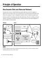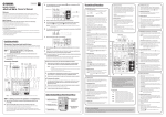
1
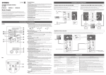
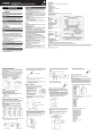
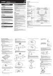
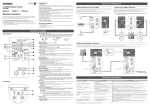
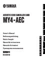
ENGLISH DEUTSCH ACOUSTIC ECHO CANCELLER CARD ESPAÑOL ITALIANO EN DE ES IT RU ZH 取 扱 説 明書 中文 FR JA 日本語 Owner’s Manual Bedienungsanleitung Mode d’emploi Manual de instrucciones Manuale di istruzioni Руководство пользователя FRANÇAIS MY4 - AEC FCC INFORMATION (U.S.A.) 1. IMPORTANT NOTICE: DO NOT MODIFY THIS UNIT! This product, when installed as indicated in the instructions contained in this manual, meets FCC requirements. Modifications not expressly approved by Yamaha may void your authority, granted by the FCC, to use the product. 2. IMPORTANT: When connecting this product to accessories and/or another product use only high quality shielded cables. Cable/s supplied with this product MUST be used. Follow all installation instructions. Failure to follow instructions could void your FCC authorization to use this product in the USA. 3. NOTE: This product has been tested and found to comply with the requirements listed in FCC Regulations, Part 15 for Class “B” digital devices. Compliance with these requirements provides a reasonable level of assurance that your use of this product in a residential environment will not result in harmful interference with other electronic devices. This equipment generates/uses radio frequencies and, if not installed and used according to the instructions found in the users manual, may cause interference harmful to the operation of other electronic devices. Compliance with FCC regulations does not guarantee that interference will not occur in all installations. If this product is found to be the source of interference, which can be determined by turning the unit “OFF” and “ON”, please try to eliminate the problem by using one of the following measures: Relocate either this product or the device that is being affected by the interference. Utilize power outlets that are on different branch (circuit breaker or fuse) circuits or install AC line filter/s. In the case of radio or TV interference, relocate/reorient the antenna. If the antenna lead-in is 300 ohm ribbon lead, change the lead-in to co-axial type cable. If these corrective measures do not produce satisfactory results, please contact the local retailer authorized to distribute this type of product. If you can not locate the appropriate retailer, please contact Yamaha Corporation of America, Electronic Service Division, 6600 Orangethorpe Ave, Buena Park, CA90620 The above statements apply ONLY to those products distributed by Yamaha Corporation of America or its subsidiaries. * This applies only to products distributed by YAMAHA CORPORATION OF AMERICA. (class B) CANADA This Class B digital apparatus complies with Canadian ICES-003. Cet appareil numérique de la classe B est conforme à la norme NMB-003 du Canada. • This applies only to products distributed by Yamaha Canada Music Ltd. • Ceci ne s’applique qu’aux produits distribués par Yamaha Canada Musique Ltée. (class B) This device complies with Part 15 of the FCC Rules. Operation is subject to the following two conditions: (1) this device may not cause harmful interference, and (2) this device must accept any interference received, including interference that may cause undesired operation. PRECAUTIONS PLEASE READ CAREFULLY BEFORE PROCEEDING * Please keep this manual in a safe place for future reference. WARNING Always follow the basic precautions listed below to avoid the possibility of serious injury or even death from electrical shock, short-circuiting, damages, fire or other hazards. These precautions include, but are not limited to, the following: • Do not install the card in any Yamaha products not specified by Yamaha for use with the card to avoid possible electrical shock, fire, or equipment damage. • Do not attempt to disassemble or modify the card. Do not apply excessive force to card connectors or other card components. Mishandling of the card may lead to shock, fire hazard, or equipment failure. • Be sure to disconnect the power cable of the host device before installing the card and connecting/disconnecting the cables (in order to eliminate shock hazard, undesired noise, and avoid equipment damage). • Turn off all peripheral devices connected to the host device before installation, and unplug all related cables (in order to eliminate shock hazard, undesired noise, and avoid equipment damage). CAUTION These precautions include, but are not limited to, the following: • Be sure to properly ground the host device to prevent electrical shock and/or malfunction. • Do not touch the metallic leads (pins) of the circuit board when handling the card. The pins are sharp and may cause hand cuts. • Wear a pair of heavy gloves during installation to avoid scratching or cutting your hands on sharp edges. • Avoid touching exposed connectors and metal parts to minimize the possibility of bad connections. • Drain all static electricity from your clothing and body before handling the card. Static electricity can damage the card. Touch an exposed metal part of the host device or other grounded object beforehand. • Do not drop the card or subject it to physical shock as this can result in breakage and/or malfunction. • Do not drop screws or other small parts inside the card. If power is applied while screws or similar metal objects are loose inside the unit the card may malfunction or be damaged. If you cannot retrieve dropped objects yourself, refer the problem to qualified Yamaha service personnel. Yamaha cannot be held responsible for damage caused by improper use or modifications to the device, or data that is lost or destroyed. • The illustrations as shown in this manual are for instructional purposes only, and may be different from the ones on your equipment. • The company names and product names in this manual are the trademarks or registered trademarks of their respective companies. Always follow the basic precautions listed below to avoid the possibility of physical injury to you or others, or damage to the device or other property. MY4-AEC Owner’s Manual 3 Information for Users on Collection and Disposal of Old Equipment This symbol on the products, packaging, and/or accompanying documents means that used electrical and electronic products should not be mixed with general household waste. For proper treatment, recovery and recycling of old products, please take them to applicable collection points, in accordance with your national legislation and the Directives 2002/96/EC. By disposing of these products correctly, you will help to save valuable resources and prevent any potential negative effects on human health and the environment which could otherwise arise from inappropriate waste handling. For more information about collection and recycling of old products, please contact your local municipality, your waste disposal service or the point of sale where you purchased the items. [For business users in the European Union] If you wish to discard electrical and electronic equipment, please contact your dealer or supplier for further information. [Information on Disposal in other Countries outside the European Union] This symbol is only valid in the European Union. If you wish to discard these items, please contact your local authorities or dealer and ask for the correct method of disposal. European models Purchaser/User Information specified in EN55103-1 and EN55103-2. Conforms to Environments: E1, E2, E3 and E4 4 MY4-AEC Owner’s Manual Introduction Thank you for choosing the Yamaha MY4-AEC. The MY4-AEC is an acoustic echo canceller card designed for use with the DME64N/24N Digital Mixing Engines that can effectively reduce troublesome acoustic echoes due to secondary pickup of speaker output and reflections from room surfaces in teleconferencing situations. It is also capable of reducing feedback as well as ambient noise from air conditioning and fans. This technology enables noise-free, highintelligibility teleconferencing in just about any environment. Four AES/EBU input and output channels are provided, all with built-in sample rate conversion capability. The MY4-AEC can also connect to digital audio devices that do not allow word clock synchronization. Installation Refer to the DME64N/24N owner’s manual for installation details. The screws on the left and right sides of the card also ground (earth) the device, so be sure to tighten them securely. Supplied Items Owner’s Manual (this document) 3-pin Euroblock plugs x 4 Cable ties x 4 MY4-AEC Owner’s Manual 5 Principle of Operation How Acoustic Echo and Noise are Reduced Acoustic echo occurs in a teleconferencing system when the sound from a speaker or reflections from surfaces of the room are picked up by a microphone and transmitted to the other party, resulting in a loss of intelligibility. Projectors and air conditioning systems also produce noise that can interfere with clear teleconferencing. The echo cancelling and noise reduction capabilities of the MY4-AEC help to achieve maximum clarity and intelligibility for smooth, effective communication. Remote Local “Hello” “Hello” “How’s business?” DME64N/24N SCENE “How’s business?” HOME UTILITY LEVEL MUTE CANCEL ENTER + MY4-AEC “How’s business” + “Hello” + fan noise Fan noise NOTE In order to reduce acoustic echo originating from the remote location, an echo canceller must be installed and active at the remote location. 6 MY4-AEC Owner’s Manual MY4-AEC Signal Flow The local and remote locations in a teleconferencing system are referred to as the “near end” and “far end”, respectively. The MY4-AEC acoustic echo canceller (AEC) works by comparing the reference signal received from the far-end with the signal from the microphone in order to determine which components of the signal are echo, and then subtracts only the far-end echo component from microphone signal. The near-end sound is thus clearly transmitted to the far end without echo. From Far-end A From Far-end B From Far-end C From Far-end D Far-end Voice A Far-end Voice B Far-end Voice C Far-end Voice D NR NR NR NR Matrix Router To Far-end 4 To Far-end 3 To Far-end 2 To Far-end 1 NR Near-end Mic. 3 FBS Reference signal Near-end Voice 3 Near-end Mic. 2 AEC AEC Near-end Voice 4 FBS AEC NR NR Near-end Mic. 4 AEC NR FBS Near-end Voice 2 Near-end Mic. 1 FBS Near-end Voice 1 FBS: Feedback suppressor NR: Noise reduction MY4-AEC Owner’s Manual 7 The Connectors and Their Functions AES/EBU IN and OUT Connectors These connectors support four channels of AES/EBU format digital audio input and output to and from the host DME64N/24N unit, but those signals are not directly routed via the MY4-AEC processing section. Signals from the host’s analog or digital inputs must be routed to the MY4AEC card’s AEC processing section via the host’s processing section in order to apply echo cancellation, as shown in the illustration below. Operational details are provided in the DME Designer owner’s manual. Built-in sample rate conversion is provided for all inputs and outputs (sample rate conversion settings are also made via the DME Designer software). Use the supplied Euroblock plugs for connection (refer to “Euroblock Connection” on page 10). NOTE The channel 3 and channel 4 inputs and outputs ([IN3/4] and [OUT3/4] in the above illustration) cannot be used when the DME64N/24N word clock sampling rate is set to 88.2 kHz or 96 kHz. 8 MY4-AEC Owner’s Manual DME Processing DME64N/24N AEC Processing MY4-AEC SRC Analog Out Mic In AES/EBU [OUT1/2][OUT3/4] SRC AES/EBU [IN1/2][IN3/4] MY4-AEC Owner’s Manual 9 Euroblock Connection Please be sure to use the supplied Euroblock plugs to connect the AES/EBU [IN] and [OUT] connectors. Cable preparation • To prepare the cable for attachment to a Euroblock approx. 7 mm connector, strip the wire as shown in the illustration using stranded wire to make connections. With a Euroblock connection, stranded wires may be prone to breakage because of metal fatigue due to the weight of the cable or due to vibration. Bundle the cables and the Euroblock tabs using the supplied cable ties (page 12). When rackmounting your equipment, use a lacing bar when possible to bundle and fasten the cables. NOTE Do not tin (plate with solder) the exposed end. • If cables will be frequently connected and disconnected, as in the case of a portable installation, we recommend that you use ferrules with insulation sleeves. Use a ferrule whose conductor portion has an external diameter of 1.6 mm or less, and a length of approximately 7 mm (such as the AI0,5-6WH made by the Phoenix Contact corporation). 10 MY4-AEC Owner’s Manual 1.6 mm or less approx. 7 mm 1 Loosen terminal screws. 2 Insert cables. Loosen. Slotted Screwdriver + – Terminal Screw G Euroblock Plug Tab NOTE 3 Securely tighten terminal screws. Pull the cables (not too strongly) to confirm that they are securely connected. A slotted screwdriver with a blade width of about 3 millimeters is recommended. 3mm or less MY4-AEC Owner’s Manual 11 4 Bundle the cables and the Euroblock tab using the supplied cable tie. NOTE Trim any excess part of the cable tie as necessary. 12 MY4-AEC Owner’s Manual 5 Insert the Euroblock plug into the AES/EBU [IN] or [OUT] connector of the MY4-AEC. Basic Connection and Setup Example 1: Teleconferencing with a Remote Location This is an example of a teleconferencing system set up to allow multiple participants to hold conferences with a remote location (“Office X”). Preparation The first step is to make the basic local (near end) connections and determine the optimum microphone and speaker locations as well as gain settings. The AEC system will have the best possible effect if these initial steps are carried out properly. 1 Prepare the following equipment. DME24N x 1 MY4-AEC x 1 Microphones x 4 Speakers x 2 NOTE Be sure to choose microphones and speakers that have good frequency response characteristics in order to ensure optimum AEC operation. 2 Connect the microphones and speakers to the analog [IN] and [OUT] connectors on the DME24N rear panel as shown in the diagram. MY4-AEC Owner’s Manual 13 Meeting Room (Near End) Microphone 1 Speaker 1 OUT (Analog) Microphone 2 Speaker 2 Microphone 3 Microphone 4 DME24N + MY4-AEC IN (Analog) 3 Make the required virtual connections in the DME Designer configuration window. • Connect the signals from microphone inputs 1 – 4 to the “Near-end Mic. 1” – “Near-end Mic. 4” inputs on the AEC component. • Place an oscillator that will be used for AEC adjustment in the configuration window and connect it to the AEC component “From Far-end A” input. • The “Far-end voice A” output is connected to the conference room speakers (SP 1 and SP 2) in parallel. 14 MY4-AEC Owner’s Manual 4 Speak into the microphones as you would during an actual conference and adjust the input gain of each channel. Adjust the DME24N HA Gain while watching the “Mic. In” meters in the AEC component editor so that the yellow segment lights only occasionally. NOTE AEC may not function properly if the gain is set too high. MY4-AEC Owner’s Manual 15 5 Open the Oscillator component editor, set the Wave Form type to “Pink,” and engage the Output section “On” button. Go back to the AEC component editor and, while watching the “Ref. In” meter, adjust the oscillator output level so that the yellow segment lights only occasionally. 16 MY4-AEC Owner’s Manual 6 Check that the ERL (Echo Return Loss) meter in the AEC component is moving. If this meter is moving over a wide range it means that a large portion of the pink noise being output from the speaker is being picked up by the corresponding microphone, and therefore a large amount of echo will be transmitted to the remote location. Carefully adjust the positions and pickup directions of the four microphones in relation to the speakers in order to reduce this echo level as much as possible. The more you can reduce the echo at this stage, the more effective the AEC will be. NOTE • If the local meeting room is very reflective or reverberant, it may be difficult to reduce the echo level sufficiently by simply repositioning the microphones and speakers. In such cases it may be necessary to apply acoustic panels to the walls or use other means to reduce room reflections. • If only the green segment of the ERL meter lights, setting the “Effect” parameter to 1 or 2 should be optimum, but if the yellow segment of the ERL meter lights an “Effect” setting of 3 or 4 will be required to produce the best results. Since the actual effectiveness of the processing will depend on the rooms in which it is used it is important make adjustments while actually connected to and conferring with the remote location. • If the input signal becomes distorted for any reason before it reaches the Near-end Mic. 1 – 4 inputs of the AEC component, echo cancelling will not function properly. 7 Enter the microphone-to-speaker distance in meters into the Acoustic Echo Canceller section “Distance” field. If multiple speakers are used, enter the distance between the microphone and nearest speaker for each channel. If the distance is less than 2 meters, use the default value of “2”. For greater distances enter the appropriate value. MY4-AEC Owner’s Manual 17 Remote Connection and Settings 1 Connect the microphones, speakers, and teleconferencing system to the analog [IN] and [OUT] connectors on the rear panel of the DME24N as shown in the diagram. Four microphones can be connected at the near-end location, allowing multiple conference participants. Meeting Room (Near End) Speaker 1 Microphone 1 Office X (Remote – Far End) Speaker 2 Microphone 2 OUT (Analog) Microphone 3 DME24N + MY4-AEC IN (Analog) Network IN/OUT (Analog) Teleconferencing system 18 MY4-AEC Owner’s Manual Microphone 4 2 Make the required virtual connections in the DME Designer configuration window. • Connect the signal from the four local microphones (Mic1 – Mic4) and the audio signal from the remote location (From Office X) to the appropriate inputs of the AEC component. • Mix the “Near-end Voice 1” – “Near-end Voice 4” outputs and the “Far-end Voice A” outputs from the AEC component and connect the mixed output in parallel to the meeting room speakers (SP 1 and SP 2). • Mix the “To Far-end 1” – “To Far-end 4” outputs from the AEC component and connect the mixed output to “To Office X” for transmission to the remote location. HINT When multiple speakers are being used in the local meeting room, be sure to connect the mixed signal to them in parallel. AEC may not function properly if the output balance between the speakers changes. MY4-AEC Owner’s Manual 19 3 Adjust the DME Designer AEC component editor parameters so that acoustic echo is effectively cancelled from the audio signal sent to Office X. Begin by checking that the connection with Office X is working properly and that conversation is possible. If echo can be heard with the default AEC section Effect setting of “1”, try increasing the setting in small increments. Echo cancellation efficiency will increase as the setting is increased, but sound quality will decrease at the same time so it is necessary to find the best setting for conditions in the local meeting room while actually listening to the audio signal. Other parameters can usually be left at their default settings. Refer to the DME Designer owner’s manual for details on the individual AEC component parameters. 20 MY4-AEC Owner’s Manual Example 2: Teleconferencing with Two Remote Locations from Two Meeting Rooms Using one MY4-AEC card, multiple participants in two meeting rooms can teleconference with two separate remote locations (“Office X” and “Office Y”). Preparation Referring to Example 1, use an oscillator component to determine the ideal microphone and speaker positions for each meeting room. The following equipment is used. DME24N x 1 MY4-AEC x 1 Microphones x 4 Speakers x 4 Remote Connection and Settings 1 Connect the microphones, speakers, and teleconferencing system to the analog [IN] and [OUT] connectors on the rear panel of the DME24N as shown in the diagram. A total of four microphones can be connected for the medium and small near-end meeting rooms, allowing multiple participants to confer simultaneously in both rooms. MY4-AEC Owner’s Manual 21 Small Meeting Room (Near End) Office X (Remote – Far End) Speaker 1 Microphone 1 Teleconferencing system Speaker 2 Microphone 2 OUT (Analog) Network IN/OUT (Analog) DME24N IN (Analog) + IN/OUT (Analog) Network MY4-AEC OUT (Analog) Speaker 1 Office Y (Remote – Far End) Teleconferencing system Speaker 2 Medium Meeting Room (Near End) 22 MY4-AEC Owner’s Manual IN (Analog) Microphone 1 Microphone 2 2 Make the required virtual connections in the DME Designer configuration window. • Connect the signal from the microphones in the small and medium local meeting rooms (Conf S Mic1/2 and Conf M – Mic1/2) and the audio signal from the remote locations (From Office X and From Office Y) to the appropriate inputs of the AEC component. • Mix the “Near-end Voice 1” and “Near-end Voice 2” outputs and the “Far-end Voice A” outputs from the AEC component and connect the mixed output in parallel to the small meeting room speakers (Conf S SP 1 and SP 2). • Mix the “Near-end Voice 3” and “Near-end Voice 4” outputs and the “Far-end Voice B” outputs from the AEC component and connect the mixed output in parallel to the medium meeting room speakers (Conf M SP 1 and SP 2). • Mix the “To Far-end 1” and “To Far-end 2” outputs from the AEC component and connect the mixed output to “To Office X” for transmission to remote Office X. • Mix the “To Far-end 3” and “To Far-end 4” outputs from the AEC component and connect the mixed output to “To Office Y” for transmission to remote Office Y. HINT When multiple speakers are being used in the same meeting room, be sure to connect the mixed signal to them in parallel. AEC may not function properly if the output balance between the speakers changes. MY4-AEC Owner’s Manual 23 3 In the Matrix Router section of the AEC component editor, select one or more of the “From Far-end A – D signals” to be used as the reference for each AEC channel 1 – 4. The “On” buttons in the Matrix Router section can be used to select microphones and locations for each meeting room. For this example the Matrix Router is set as shown below. With these settings it is possible to simultaneously hold independent conferences between the small meeting room and Office X (Far-end A) using AEC channels 1 and 2, and between the medium meeting room and Office Y (Far-end B) using AEC channels 3 and 4. From Far-end A From Far-end B 24 MY4-AEC Owner’s Manual Appendix Specifications GENERAL SPECIFICATIONS Sampling Frequency 44.1kHz-10% to 48kHz+6%, 88.2kHz-10% to 96kHz+6% Power requirements 5V : 395mA 3.3V : 295mA Temperature Range Operating 0 to +40°C Storage -20 to +60°C Weight 160g DIGITAL INPUT/OUTPUT CHARACTERISTICS Terminal IN 1/2, 3/4 OUT 1/2, 3/4 Format Audio Data Length Level Connector AES/EBU 24bit RS422 Euroblock AES/EBU (Professional use) 24bit RS422 Euroblock MY4-AEC Owner’s Manual 183 Dimensions 164.1 176.1 (12) 120 40 unit: mm 184 MY4-AEC Owner’s Manual * Specifications and descriptions in this owner’s manual are for information purposes only. Yamaha Corp. reserves the right to change or modify products or specifications at any time without prior notice. Since specifications, equipment or options may not be the same in every locale, please check with your Yamaha dealer. * Die technischen Daten und Beschreibungen in dieser Bedienungsanleitung dienen nur der Information. Yamaha Corp. behält sich das Recht vor, Produkte oder deren technische Daten jederzeit ohne vorherige Ankündigung zu verändern oder zu modifizieren. Da die technischen Daten, das Gerät selbst oder Sonderzubehör nicht in jedem Land gleich sind, setzen Sie sich im Zweifel bitte mit Ihrem Yamaha-Händler in Verbindung. * Les caractéristiques techniques et les descriptions du mode d’emploi ne sont données que pour information. Yamaha Corp. se réserve le droit de changer ou modifier les produits et leurs caractéristiques techniques à tout moment sans aucun avis. Du fait que les caractéristiques techniques, les équipements et les options peuvent différer d’un pays à l’autre, adressez-vous au distributeur Yamaha le plus proche. * Las especificaciones y descripciones de este manual del propietario tienen sólo el propósito de servir como información. Yamaha Corp. se reserva el derecho a efectuar cambios o modificaciones en los productos o especificaciones en cualquier momento sin previo aviso. Puesto que las especificaciones, equipos u opciones pueden no ser las mismas en todos los mercados, solicite información a su distribuidor Yamaha. * Le specifiche e le descrizioni presenti in questo manuale sono fornite a fini puramente informativi. Yamaha Corp. si riserva il diritto di modificare prodotti o specifiche in qualsiasi momento senza preavviso. Dato che le specifiche, le apparecchiature o le opzioni possono essere diverse da paese a paese, verificarle con il proprio rappresentante Yamaha. * 仕様および外観は改良のため、予告なく変更することがあります。 MY4-AEC Owner’s Manual 185 Memo 186 MY4-AEC Owner’s Manual Memo MY4-AEC Owner’s Manual 187 188 MY4-AEC Owner’s Manual MY4-AEC Owner’s Manual 189 For details of products, please contact your nearest Yamaha representative or the authorized distributor listed below. NORTH AMERICA CANADA Yamaha Canada Music Ltd. 135 Milner Avenue, Toronto, Ontario, M1S 3R1, Canada Tel: 416-298-1311 U.S.A. PANAMA AND OTHER LATIN AMERICAN COUNTRIES/ CARIBBEAN COUNTRIES Yamaha Music Latin America, S.A. Torre Banco General, Piso No.7, Marbella, Calle 47 y Aquilino de la Guardia, Ciudad de Panamá, República de Panamá Tel: +507-269-5311 Yamaha Corporation of America 6600 Orangethorpe Avenue, Buena Park, CA 90620, U.S.A. Tel: 714-522-9011 CENTRAL & SOUTH AMERICA MEXICO Yamaha de México, S.A. de C.V. Av. Insurgentes Sur 1647 Piso 9, Col. San José Insurgentes, Delegación Benito Juárez, México, D.F., C.P. 03900 Tel: 55-5804-0600 BRAZIL Yamaha Musical do Brasil Ltda. Rua Joaquim Floriano, 913 - 4º andar, Itaim Bibi, CEP 04534-013 São Paulo, SP. BRAZIL Tel: 011-3704-1377 ARGENTINA Yamaha Music Latin America, S.A., Sucursal Argentina Olga Cossettini 1553, Piso 4 Norte, Madero Este-C1107CEK Buenos Aires, Argentina Tel: 011-4119-7000 VENEZUELA Yamaha Music Latin America, S.A., Sucursal Venezuela C.C. Manzanares Plaza P4 Ofic. 0401- Manzanares-Baruta Caracas Venezuela Tel: 58-212-943-1877 EUROPE THE UNITED KINGDOM/IRELAND Yamaha Music Europe GmbH (UK) Sherbourne Drive, Tilbrook, Milton Keynes, MK7 8BL, U.K. Tel: 01908-366700 GERMANY Yamaha Music Europe GmbH Siemensstraße 22-34, 25462 Rellingen, Germany Tel: 04101-3030 SWITZERLAND/LIECHTENSTEIN Yamaha Music Europe GmbH Branch Switzerland in Zürich Seefeldstrasse 94, 8008 Zürich, Switzerland Tel: 044-387-8080 AUSTRIA/BULGARIA Yamaha Music Europe GmbH Branch Austria Schleiergasse 20, A-1100 Wien, Austria Tel: 01-60203900 CZECH REPUBLIC/HUNGARY/ ROMANIA/SLOVAKIA/SLOVENIA Yamaha Music Europe GmbH Branch Austria (Central Eastern Europe Office) Schleiergasse 20, A-1100 Wien, Austria Tel: 01-60203900 POLAND/LITHUANIA/LATVIA/ ESTONIA Yamaha Music Europe GmbH Branch Poland Office ul. Wrotkowa 14 02-553 Warsaw, Poland Tel: 022-500-2925 190 MY4-AEC Owner’s Manual MALTA Olimpus Music Ltd. The Emporium, Level 3, St. Louis Street Msida MSD06 Tel: 02133-2144 NETHERLANDS/BELGIUM/LUXEMBOURG Yamaha Music Europe Branch Benelux Clarissenhof 5-b, 4133 AB Vianen, Netherlands Tel: 0347-358 040 FRANCE Yamaha Music Europe 7 rue Ambroise Croizat, Zone d'activites Pariest, 77183 Croissy-Beaubourg, France Tel: 01-64-61-4000 ITALY Yamaha Music Europe GmbH, Branch Italy Viale Italia 88, 20020 Lainate (Milano), Italy Tel: 02-935-771 SPAIN/PORTUGAL Yamaha Music Europe GmbH Ibérica, Sucursal en España Ctra. de la Coruna km. 17,200, 28231 Las Rozas (Madrid), Spain Tel: +34-91-639-88-88 GREECE Philippos Nakas S.A. The Music House 147 Skiathou Street, 112-55 Athens, Greece Tel: 01-228 2160 SWEDEN/FINLAND/ICELAND Yamaha Music Europe GmbH Germany filial Scandinavia J. A. Wettergrensgata 1, Box 30053 S-400 43 Göteborg, Sweden Tel: +46 31 89 34 00 DENMARK Yamaha Music Europe GmbH, Tyskland – filial Denmark Generatorvej 6A, DK-2730 Herlev, Denmark Tel: 44 92 49 00 NORWAY Yamaha Music Europe GmbH Germany - Norwegian Branch Grini Næringspark 1, N-1361 Østerås, Norway Tel: 67 16 78 00 RUSSIA Yamaha Music (Russia) LLC. Room 37, bld. 7, Kievskaya street, Moscow, 121059, Russia Tel: 495 626 5005 OTHER EUROPEAN COUNTRIES Yamaha Music Europe GmbH Siemensstraße 22-34, 25462 Rellingen, Germany Tel: +49-4101-3030 Yamaha Music Gulf FZE Office JAFZA 16-512, P.O.Box 17328, Jebel Ali - Dubai, UAE Tel: +971-4-881-5868 Yamaha Music & Electronics (China) Co.,Ltd. 2F, Yunhedasha, 1818 Xinzha-lu, Jingan-qu, Shanghai, China Tel: 021-6247-2211 INDIA Yamaha Music India Pvt. Ltd. Spazedge building, Ground Floor, Tower A, Sector 47, Gurgaon- Sohna Road, Gurgaon, Haryana, India Tel: 0124-485-3300 INDONESIA Yamaha Music Center Bldg. Jalan Jend. Gatot Subroto Kav. 4, Jakarta 12930, Indonesia Tel: 021-520-2577 KOREA MIDDLE EAST Yamaha Music Korea Ltd. TURKEY Yamaha Music Europe GmbH Merkezi Almanya Türkiye İstanbul Şubesi Maslak Meydan Sokak No:5 Spring Giz Plaza Bağımsız Böl. No:3, 34398 Şişli İstanbul Tel: +90-212-999-8010 CYPRUS Yamaha Music Europe GmbH Siemensstraße 22-34, 25462 Rellingen, Germany Tel: 04101-3030 OTHER COUNTRIES Office JAFZA 16-512, P.O.Box 17328, Jebel Ali - Dubai, U.A.E Tel: +971-4-881-5868 PA36 THE PEOPLE’S REPUBLIC OF CHINA PT. Yamaha Musik Indonesia (Distributor) AFRICA Yamaha Music Gulf FZE ASIA 8F, 9F, Dongsung Bldg. 158-9 SamsungDong, Kangnam-Gu, Seoul, Korea Tel: 02-3467-3300 MALAYSIA Yamaha Music (Malaysia) Sdn., Bhd. No.8, Jalan Perbandaran, Kelana Jaya, 47301 Petaling Jaya, Selangor, Malaysia Tel: 03-78030900 SINGAPORE Yamaha Music (Asia) Private Limited Block 202 Hougang Street 21, #02-00, Singapore 530202, Singapore Tel: 65-6747-4374 TAIWAN Yamaha Music & Electronics Taiwan Co.,Ltd. 3F, No.6, Section 2 Nan-Jing East Road, Taipei, Taiwan R.O.C. Tel: 02-2511-8688 THAILAND Siam Music Yamaha Co., Ltd. 3, 4, 15 and 16th floor, Siam Motors Building, 891/1 Rama 1 Road, Wangmai, Pathumwan, Bangkok 10330, Thailand Tel: 02-215-2622 VIETNAM Yamaha Music Vietnam Company Limited 15th Floor, Nam A Bank Tower, 201-203 Cach Mang Thang Tam St., Ward 4, Dist.3, Ho Chi Minh City, Vietnam Tel: +84-8-3818-1122 OTHER ASIAN COUNTRIES Yamaha Corporation Sales & Marketing Division Nakazawa-cho 10-1, Naka-ku, Hamamatsu, Japan 430-8650 Tel: +81-53-460-2312 OCEANIA AUSTRALIA Yamaha Music Australia Pty. Ltd. Level 1, 99 Queensbridge Street, Southbank, Victoria 3006, Australia Tel: 3-9693-5111 COUNTRIES AND TRUST TERRITORIES IN PACIFIC OCEAN Yamaha Corporation, Asia-Pacific Music Marketing Group Nakazawa-cho 10-1, Naka-ku, Hamamatsu, Japan 430-8650 Tel: +81-53-460-2313 HEAD OFFICEYamaha Corporation, Audio Products Sales and Marketing Division Nakazawa-cho 10-1, Naka-ku, Hamamatsu, Japan 430-8650 MY4-AEC Owner’s Manual 191 ENGLISH DEUTSCH ACOUSTIC ECHO CANCELLER CARD http://www.yamahaproaudio.com/ Yamaha Manual Library http://www.yamaha.co.jp/manual/ 312YJTO-B0 Printed in Japan WW75420 ESPAÑOL ITALIANO EN DE ES IT RU ZH 取扱説明書 中文 FR JA 日本語 Yamaha Pro Audio global web site C.S.G., PA Development Division © 2011-2013 Yamaha Corporation Owner’s Manual Bedienungsanleitung Mode d’emploi Manual de instrucciones Manuale di istruzioni Руководство пользователя FRANÇAIS MY4 - AEC