1
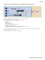
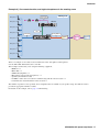
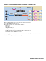
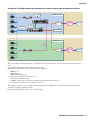
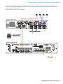
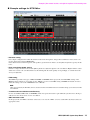
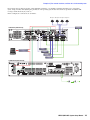
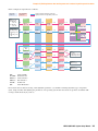
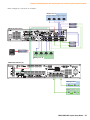
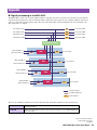
MTX5-D/MY4-AEC System Setup Manual By using the MTX5-D and the MY4-AEC, you can configure a remote conferencing system. Please read this manual when you want to configure a remote conferencing system using the MTX5-D and the MY4-AEC. This manual provides a simple explanation of the setup procedure, using the project file that is preinstalled in MTX Editor. Understanding how the inputs and outputs of the MTX5-D and the MY4-AEC are related will allow you to configure a system that meets your needs. Please refer to the owner’s manual on devices about the details, and refer to the “MTX Editor User’s Manual” (PDF file) about the details of MTX Editor. Special Notice • The software and this manual are the exclusive copyrights of Yamaha Corporation. • Copying of the software or reproduction of this manual in whole or in part by any means is expressly forbidden without the written consent of the manufacturer. • Yamaha makes no representations or warranties with regard to the use of the software and documentation and cannot be held responsible for the results of the use of this manual and the software. • Future upgrades of application and system software and any changes in specifications and functions will be announced at the following website. http://www.yamahaproaudio.com/ • The screen displays as illustrated in this manual are for instructional purposes, and may appear somewhat different from the screens which appear on your computer. • Windows is a registered trademark of Microsoft® Corporation in the United States and other countries. • The company names and product names in this manual are the trademarks or registered trademarks of their respective companies. EN MTX5-D/MY4-AEC System Setup Manual 1 Introduction The MTX5-D/MY4-AEC system setup manual explains settings for when an MY4-AEC is installed in the MTX5-D’s [SLOT]. As examples, we will provide simple explanations of the typical setups described below. For detailed parameter settings, refer to “MTX Editor User’s Manual.” When you install MTX Editor, the four example files described here will be found in the following folders. 32-bit operating system C:\Program Files\Yamaha\MTX Editor\V*.*\ProjectFile 64-bit operating system C:\Program Files(x86)\Yamaha\MTX Editor\V*.*\ProjectFile *.* will be the version of the installed MTX Editor. Example File name Example 1) One remote location, and four microphones in the meeting room AEC 4Mic 1RemoteLocation-*.mtx Example 2) One remote location, and eight microphones in the meeting room AEC 8Mic 1RemoteLocation-*.mtx Example 3) Four remote locations, and four microphones in the meeting room AEC 4Mic 4RemoteLocation-*.mtx Example 4) Dividing between two meeting rooms and conferencing with separate locations AEC 2MeetingRoom 2RemoteLocation-*.mtx -* is a management number. In some cases, there will be no -*. Glossary Glossary Description Local Your own meeting room within the remote conferencing system. Also called “near-end.” Remote The other party’s meeting room within the remote conferencing system. Also called “far-end.” From Far-end The input signal from the remote location (the other party) Far-end Voice The signal from the remote location reproduced via your local speakers Near-end Mic. The input signal from the microphone(s) of the remote location Near-end Voice The signal from the local microphone(s) reproduced via the local speakers To Far-end The signal of the local microphone(s), processed by echo cancellation and sent to the remote location CODEC A device for transmitting and receiving data via a digital communication network MTX5-D/MY4-AEC System Setup Manual 2 Introduction Example 1) One remote location, and four microphones in the meeting room Microphone 1 Analog OUT Meeting room XMV4140 Microphone 2 CODEC Microphone 3 Network Remote A YDIF Analog IN MTX5-D Analog IN/OUT Microphone 4 This is an example of one remote location with four or fewer local microphones. Use the AEC 4Mic 1RemoteLocation-*.mtx file. This example assumes that you’re using the following equipment. • • • • • • • MTX5-D 1 MY4-AEC 1 XMV4140 (Amplifier) 1 Microphones (Boundary microphones) 4 Speakers (the number needed) CODEC or other devices needed for communicating with the remote location 1 Communication network with the remote location 1 The number of speakers is not specified; choose amplifiers that are suitable for your speaker setup. You will also need to provide the appropriate number of cables. For details on this example, refer to page 7 and following. MTX5-D/MY4-AEC System Setup Manual 3 Introduction Example 2) One remote location, and eight microphones in the meeting room Microphone 1 Meeting room Analog OUT XMV4140 Microphone 2 Microphone 3 YDIF Microphone 4 Analog IN MTX5-D Analog IN/OUT CODEC Network Remote A Microphone 5 Microphone 6 Microphone 7 Microphone 8 This is an example of one remote location with between five and eight local microphones. Use the AEC 8Mic 1RemoteLocation-*.mtx file. This example assumes that you’re using the following equipment. • • • • • • • MTX5-D 1 MY4-AEC 1 XMV4140 (Amplifier) 1 Microphones (Gooseneck microphones) 8 Speakers (the number needed) CODEC or other devices needed for communicating with the remote location 1 Communication network with the remote location 1 The number of speakers is not specified; choose amplifiers that are suitable for your speaker setup. You will also need to provide the appropriate number of cables. For details on this example, refer to page 11 and following. MTX5-D/MY4-AEC System Setup Manual 4 Introduction Example 3) Four remote locations, and four microphones in the meeting room Analog OUT Meeting room XMV4140 Microphone 1 Microphone 2 CODEC A Network Remote A CODEC B Network Remote B CODEC C Network Remote C CODEC D Network Remote D YDIF Analog IN MTX5-D Analog IN/OUT Microphone 3 Microphone 4 This is an example of multiple remote locations, with four or fewer local microphones. Use the AEC 4Mic 4RemoteLocation-*.mtx file. This example assumes that you’re using the following equipment. • • • • • • • MTX5-D 1 MY4-AEC 1 XMV4140 (Amplifier) 1 Microphones (Boundary microphones) 4 Speakers (the number needed) CODEC or other devices needed for communicating with the remote location 4 Communication networks with the remote location 4 The number of speakers is not specified; choose amplifiers that are suitable for your speaker setup. You will also need to provide the appropriate number of cables. For details on this example, refer to page 15 and following. MTX5-D/MY4-AEC System Setup Manual 5 Introduction Example 4) Dividing between two meeting rooms and conferencing with separate locations Microphone 1 Analog OUT Meeting room ‘A’ XMV4140 Microphone 2 CODEC A Microphone 3 Network Remote A Network Remote B YDIF Analog IN MTX5-D Microphone 4 Analog IN/OUT Microphone 1 Meeting room ‘B’ Analog OUT Microphone 2 Microphone 3 CODEC B Microphone 4 This is an example in which participants are divided between two meeting rooms and are conferencing with separate locations. Use the AEC 2MeetingRoom 2RemoteLocation-*.mtx file. This example assumes that you’re using the following equipment. • • • • • • • MTX5-D 1 MY4-AEC 1 XMV4140 (Amplifier) 1 Microphones (Boundary microphones) 8 Speakers (the number needed) CODEC or other devices needed for communicating with the remote location 2 Communication networks with the remote location 2 The number of speakers is not specified; choose amplifiers that are suitable for your speaker setup. You will also need to provide the appropriate number of cables. For details on this example, refer to page 19 and following. MTX5-D/MY4-AEC System Setup Manual 6 Example 1) One remote location, and four microphones in the meeting room Here we explain the main points when adjusting the example setup shown below. Microphone 1 Analog OUT Meeting room XMV4140 Microphone 2 CODEC Network Microphone 3 Remote A YDIF Analog IN MTX5-D Analog IN/OUT Microphone 4 In this example, the signal flow is as follows. Adjustable parameter Signal path with adjustable parameters Non-adjustable parameter Patched directly to AEC Signal path with non-adjustable parameters Input Matrix Zone Output AEC 4 ch Mic In ([INPUT] 1–4) NE NEVoice Secondary FBS 1 ch CODEC ([INPUT] 5) InputCh 9 1 ch Matrix 10 1 ch ZONE 10 1 ch OutputCh 6 1 ch FromFE FEVoice NR = ON NR = ON To FE Primary FBS 4 ch 1 ch 4 ch NE: FromFE: NEVoice: FEVoice: TO FE: NR: InputCh 5–8 4 ch Direct Input 17 1 ch InputCh 1–4 4 ch Matrix 9 Matrix 1 1 ch 1 ch ZONE 9 ZONE 1 1 ch 1 ch OutputCh 5 1 ch OutputCh 1 1 ch YDIF 1 XMV (A ch) CODEC ([OUTPUT] 1) Near-end Mic From Far-end Near-end Voice Far-end Voice To Far-end Noise Reduction MTX5-D/MY4-AEC System Setup Manual 7 Example 1) One remote location, and four microphones in the meeting room For locations that are listed as having “Non-adjustable parameter,” you should avoid using Dynamics-type components (Gate, Comp, Ducker) and adjusting the parameters of an operating system after it has been set up. Echo cancellation will no longer work effectively if you do so. In this example, the connections are as follows. Microphone Microphone Microphone Microphone 4 3 2 1 MTX5-D (UNIT ID=01) RECORDER CODEC Network Switch Computer ON XMV4140 (UNIT ID=30) ON 1 2 3 4 5 6 7 8 MTX5-D/MY4-AEC System Setup Manual 8 Example 1) One remote location, and four microphones in the meeting room Example settings for MTX Editor • Distance setting For a simple configuration in which the distance between the microphone and speaker is within two meters, there is no need to change this setting in MTX Editor. If the distance between the microphone and speaker is greater than two meters, use the [Distance] knob to specify the distance. • Echo cancellation depth setting If there is a large amount of echo, use the [Effect] list box to adjust the depth of echo cancellation. Higher numeric values allow more echoes to be cancelled. However, this will degrade the audio quality correspondingly, so consider the tradeoff as you adjust this. • FBS setting The MTX5-D provides two types of FBS: DYNAMIC and FIXED. In this project file, the DYNAMIC setting of the MTX5-D unit is turned on. As needed, use the “INPUT” screen to set the FBS setting to FIXED. For details on how to make this setting, refer to the “MTX Editor User’s Manual.” NOTE FBS is also provided by the MY4-AEC; however, because the FBS of the MTX5-D allows more flexible settings, you should use the FBS of the MTX5-D. • To make echo cancellation work effectively Do not use GATE, COMP, AGC, or LIMITER, and do not operate the faders or gain while the system is in use. Doing so will decrease the effectiveness of echo cancellation. • XMV attenuator value In this project file, the XMV’s attenuator value is set to -99. Use the “XMV” screen to set the CH A attenuator value to an appropriate value. MTX5-D/MY4-AEC System Setup Manual 9 Example 1) One remote location, and four microphones in the meeting room Examples of adjusting the settings • Adjusting the volume of the audio signal from the remote location Operate the fader of input channel 9. While you watch the level meter, adjust the input level so that the yellow indicator lights occasionally. • Adjusting the volume of a microphone of the local location In the “MY4-AEC” screen, click the [Near-end Mic.] button to access the parameter editing screen, and operate the [GAIN] knob. While you watch the Mic In. meter, adjust the HA gain so that the yellow indicator lights occasionally. • Adjusting the volume of the speaker of the local location Adjust the input level as described in “Adjusting the volume of the audio signal from the remote location” and “Adjusting the volume of a microphone of the local location,” above. • If you don’t want the audio from the local microphone to be output from the speaker In the “MATRIX” screen, turn off the sends of input channels 5 through 8. • If you want to connect recording/playback device To record, connect your device to the MTX5-D’s “OUTPUT” 7 connector. To play back, connect your device to the MTX5-D’s “ST IN” 2L connector. When recording, turn on the [ON] button of input channel STIN2L. When playing back, turn on the [ON] button of output channel OUT7. NOTE Feedback may occur if you have connected a type of recording/playback device that outputs the input signal while recording is paused. If feedback occurs, click the [ON] button of input channel STIN2L to turn it off. When playing back, turn this button back on. MTX5-D/MY4-AEC System Setup Manual 10 Example 2) One remote location, and eight microphones in the meeting room Microphone 1 Meeting room Analog OUT XMV4140 Microphone 2 Microphone 3 YDIF Microphone 4 Analog IN MTX5-D Analog IN/OUT Network CODEC Remote A Microphone 5 Microphone 6 Microphone 7 Microphone 8 In this example, the signal flow is as follows. Adjustable parameter Signal path with adjustable parameters Non-adjustable parameter Signal path with non-adjustable parameters Input 8 ch Mic In ([INPUT] 1–8) Direct Ch 17–24 Matrix 8 ch Matrix 11–14 Zone 4 ch ZONE 11–14 Output 4 ch OutputCh 6–9 AEC 4 ch NE NEVoice Secondary FBS 1 ch CODEC ([ST IN] 1L) InputCh 9 1 ch Matrix 10 1 ch ZONE 10 1 ch OutputCh 5 1 ch FromFE FEVoice NR = ON NR = ON To FE Primary FBS 4 ch 1 ch 4 ch InputCh 5–8 4 ch Input Ch 10 1 ch InputCh 1–4 4 ch Matrix 9 Matrix 1 1 ch 1 ch ZONE 9 ZONE 1 1 ch 1 ch OutputCh 2 1 ch OutputCh 1 1 ch YDIF 1 XMV (A ch) CODEC ([OUTPUT] 1) MTX5-D/MY4-AEC System Setup Manual 11 Example 2) One remote location, and eight microphones in the meeting room NE: FromFE: NEVoice: FEVoice: TO FE: NR: Near-end Mic From Far-end Near-end Voice Far-end Voice To Far-end Noise Reduction For locations that are listed as having “Non-adjustable parameter,” you should avoid using Dynamics-type components (Gate, Comp, Ducker) and adjusting the parameters of an operating system after it has been set up. Echo cancellation will no longer work effectively if you do so. In this example, the connections are as follows. Microphone Microphone Microphone Microphone 4 3 2 1 MTX5-D (UNIT ID=01) RECORDER CODEC Network Switch Microphone Microphone Microphone Microphone 8 7 6 5 Computer ON XMV4140 (UNIT ID=30) ON 1 2 3 4 5 6 7 8 MTX5-D/MY4-AEC System Setup Manual 12 Example 2) One remote location, and eight microphones in the meeting room Example settings for MTX Editor • Distance setting For a simple configuration in which the distance between the microphone and speaker is within two meters, there is no need to change this setting in MTX Editor. If the distance between the microphone and speaker is greater than two meters, use the [Distance] knob to specify the distance. • Echo cancellation depth setting If there is a large amount of echo, use the [Effect] list box to adjust the depth of echo cancellation. Higher numeric values allow more echoes to be cancelled. However, this will degrade the audio quality correspondingly, so consider the tradeoff as you adjust this. • FBS setting The MTX5-D provides two types of FBS: DYNAMIC and FIXED. In this project file, the DYNAMIC setting of the MTX5-D unit is turned on. As needed, use the “INPUT” screen to set the FBS setting to FIXED. For details on how to make this setting, refer to the “MTX Editor User’s Manual.” NOTE FBS is also provided by the MY4-AEC; however, because the FBS of the MTX5-D allows more flexible settings, you should use the FBS of the MTX5-D. • To make echo cancellation work effectively Do not use GATE, COMP, AGC, or LIMITER, and do not operate the faders or gain while the system is in use. Doing so will decrease the effectiveness of echo cancellation. • XMV attenuator value In this project file, the XMV’s attenuator value is set to -99. Use the “XMV” screen to set the CH A attenuator value to an appropriate value. MTX5-D/MY4-AEC System Setup Manual 13 Example 2) One remote location, and eight microphones in the meeting room Examples of adjusting the settings • Adjusting the volume of the audio signal from the remote location Operate the fader of input channel 9. While you watch the level meter, adjust the input level so that the yellow indicator lights occasionally. • Adjusting the volume of a microphone of the local location Operate the faders of input channels 17 through 24. While you watch the level meter, adjust the input level so that the yellow indicator lights occasionally. • Adjusting the volume of the speaker of the local location Adjust the input level as described in “Adjusting the volume of the audio signal from the remote location” and “Adjusting the volume of a microphone of the local location,” above. • If you don’t want the audio from the local microphone to be output from the speaker In the “MATRIX” screen, turn off the sends of input channels 5 through 8. • If you want to connect recording/playback device To record, connect your device to the MTX5-D’s “OUTPUT” 7 connector. To play back, connect your device to the MTX5-D’s “ST IN” 2L connector. When recording, turn on the [ON] button of input channel STIN2L. When playing back, turn on the [ON] button of output channel OUT7. NOTE Feedback may occur if you have connected a type of recording/playback device that outputs the input signal while recording is paused. If feedback occurs, click the [ON] button of input channel STIN2L to turn it off. When playing back, turn this button back on. MTX5-D/MY4-AEC System Setup Manual 14 Example 3) Four remote locations, and four mics in the meeting room Analog OUT Meeting room XMV4140 Microphone 1 Microphone 2 CODEC A Network Remote A CODEC B Network Remote B CODEC C Network Remote C CODEC D Network Remote D YDIF Analog IN MTX5-D Analog IN/OUT Microphone 3 Microphone 4 In this example, the signal flow is as follows. Adjustable parameter Signal path with adjustable parameters Non-adjustable parameter Patched directly to AEC Signal path with non-adjustable parameters Input Matrix Zone Output AEC 4 ch Mic In ([INPUT] 1–4) NE NEVoice Secondary FBS 4 ch CODEC ([INPUT] 5–8) InputCh 9–12 4 ch Matrix 10 1 ch ZONE 10 1 ch OutputCh 6 1 ch FromFE FEVoice NR = ON NR = ON To FE Primary FBS 4 ch 1 ch 4 ch NE: FromFE: NEVoice: FEVoice: TO FE: NR: InputCh 5–8 4 ch Direct Input 17 1 ch InputCh 1–4 4 ch Matrix 9 Matrix 1 1 ch 1 ch ZONE 9 ZONE 1 1 ch 1 ch OutputCh 5 1 ch OutputCh 1–4 4 ch YDIF 1 XMV (A ch) CODEC ([OUTPUT] 1–4) Near-end Mic From Far-end Near-end Voice Far-end Voice To Far-end Noise Reduction MTX5-D/MY4-AEC System Setup Manual 15 Example 3) Four remote locations, and four mics in the meeting room For locations that are listed as having “Non-adjustable parameter,” you should avoid using Dynamics-type components (Gate, Comp, Ducker) and adjusting the parameters of an operating system after it has been set up. Echo cancellation will no longer work effectively if you do so. In this example, the connections are as follows. Microphone Microphone Microphone Microphone 4 3 2 1 MTX5-D (UNIT ID=01) RECORDER CODEC D Network Switch CODEC C CODEC B Computer CODEC A ON XMV4140 (UNIT ID=30) ON 1 2 3 4 5 6 7 8 MTX5-D/MY4-AEC System Setup Manual 16 Example 3) Four remote locations, and four mics in the meeting room Example settings for MTX Editor • Distance setting For a simple configuration in which the distance between the microphone and speaker is within two meters, there is no need to change this setting in MTX Editor. If the distance between the microphone and speaker is greater than two meters, use the [Distance] knob to specify the distance. • Echo cancellation depth setting If there is a large amount of echo, use the [Effect] list box to adjust the depth of echo cancellation. Higher numeric values allow more echoes to be cancelled. However, this will degrade the audio quality correspondingly, so consider the tradeoff as you adjust this. • FBS setting The MTX5-D provides two types of FBS: DYNAMIC and FIXED. In this project file, the DYNAMIC setting of the MTX5-D unit is turned on. As needed, use the “INPUT” screen to set the FBS setting to FIXED. For details on how to make this setting, refer to the “MTX Editor User’s Manual.” NOTE FBS is also provided by the MY4-AEC; however, because the FBS of the MTX5-D allows more flexible settings, you should use the FBS of the MTX5-D. • To make echo cancellation work effectively Do not use GATE, COMP, AGC, or LIMITER, and do not operate the faders or gain while the system is in use. Doing so will decrease the effectiveness of echo cancellation. • XMV attenuator value In this project file, the XMV’s attenuator value is set to -99. Use the “XMV” screen to set the CH A attenuator value to an appropriate value. MTX5-D/MY4-AEC System Setup Manual 17 Example 3) Four remote locations, and four mics in the meeting room Examples of adjusting the settings • Adjusting the volume of the audio signal from the remote location Operate the fader of input channels 9 through 12. While you watch the level meter, adjust the input level so that the yellow indicator lights occasionally. • Adjusting the volume of a microphone of the local location In the “MY4-AEC” screen, click the [Near-end Mic.] button to access the parameter editing screen, and operate the [GAIN] knob. While you watch the Mic In. meter, adjust the HA gain so that the yellow indicator lights occasionally. • Adjusting the volume of the speaker of the local location Adjust the input level as described in “Adjusting the volume of the audio signal from the remote location” and “Adjusting the volume of a microphone of the local location,” above. • If you don’t want the audio from the local microphone to be output from the speaker In the “MATRIX” screen, turn off the sends of input channels 5 through 8. • If you want to connect recording/playback device To record, connect your device to the MTX5-D’s “OUTPUT” 7 connector. To play back, connect your device to the MTX5-D’s “ST IN” 2L connector. When recording, turn on the [ON] button of input channel STIN2L. When playing back, turn on the [ON] button of output channel OUT7. NOTE Feedback may occur if you have connected a type of recording/playback device that outputs the input signal while recording is paused. If feedback occurs, click the [ON] button of input channel STIN2L to turn it off. When playing back, turn this button back on. MTX5-D/MY4-AEC System Setup Manual 18 Example 4) Dividing between two meeting rooms and conferencing with separate locations Microphone 1 Analog OUT Meeting room ‘A’ XMV4140 Microphone 2 CODEC A Microphone 3 Network Remote A Network Remote B YDIF Analog IN MTX5-D Microphone 4 Analog IN/OUT Microphone 1 Meeting room ‘B’ Analog OUT Microphone 2 Microphone 3 CODEC B Microphone 4 MTX5-D/MY4-AEC System Setup Manual 19 Example 4) Dividing between two meeting rooms and conferencing with separate locations In this example, the signal flow is as follows. Adjustable parameter Signal path with adjustable parameters Non-adjustable parameter Signal path with non-adjustable parameters Input Mic In ([INPUT] 1–8) 1–4: Meeting room ‘A’ 5–8: Meeting room ‘B’ 8 ch Direct Ch17–24 Matrix 8 ch Matrix 11–14 Zone 4 ch ZONE 11–14 Output 4 ch OutputCh 11–14 AEC 4 ch NE NEVoice Secondary FBS CODEC A&B ([ST IN] 2L/2R) 2 ch L: Meeting room ‘A’ R: Meeting room ‘B’ InputCh 9–10 2 ch Matrix 5–6 2 ch ZONE 5–6 2 ch OutputCh 9–10 2 ch FromFE FEVoice NR = ON NR = ON To FE Primary FBS 4 ch InputCh 2, 4, 6, 8 2 ch Matrix 9 1 ch ZONE 9 1 ch OutputCh 2 1 ch YDIF 1 2 ch 1 ch 2 ch Input Ch 11–12 XMV (A, C Ch) A: Meeting room ‘A’ C: Meeting room ‘B’ Matrix 10 1 ch ZONE 10 1 ch OutputCh 6 Matrix 1 1 ch ZONE 1 1 ch OutputCh 1 1 ch CODEC A ([OUTPUT] 1) Matrix 2 1 ch ZONE 2 1 ch OutputCh 5 1 ch CODEC B ([OUTPUT] 4) 1 ch YDIF 2 1 ch 2 ch 4 ch NE: FromFE: NEVoice: FEVoice: TO FE: NR: InputCh 1, 3, 5, 7 2 ch Near-end Mic From Far-end Near-end Voice Far-end Voice To Far-end Noise Reduction For locations that are listed as having “Non-adjustable parameter,” you should avoid using Dynamics-type components (Gate, Comp, Ducker) and adjusting the parameters of an operating system after it has been set up. Echo cancellation will no longer work effectively if you do so. MTX5-D/MY4-AEC System Setup Manual 20 Example 4) Dividing between two meeting rooms and conferencing with separate locations In this example, the connections are as follows. Meeting room ‘A’ Microphone Microphone Microphone Microphone 4 3 2 1 RECORDER B RECORDER A MTX5-D (UNIT ID=01) CODEC A CODEC B Network Switch Microphone Microphone Microphone Microphone 4 3 2 1 Computer Meeting room ‘B’ ON XMV4140 (UNIT ID=30) ON 1 2 3 4 5 6 7 8 Meeting room ‘A’ Meeting room ‘B’ MTX5-D/MY4-AEC System Setup Manual 21 Example 4) Dividing between two meeting rooms and conferencing with separate locations Example settings for MTX Editor • Distance setting For a simple configuration in which the distance between the microphone and speaker is within two meters, there is no need to change this setting in MTX Editor. If the distance between the microphone and speaker is greater than two meters, use the [Distance] knob to specify the distance. • Echo cancellation depth setting If there is a large amount of echo, use the [Effect] list box to adjust the depth of echo cancellation. Higher numeric values allow more echoes to be cancelled. However, this will degrade the audio quality correspondingly, so consider the tradeoff as you adjust this. • FBS setting The MTX5-D provides two types of FBS: DYNAMIC and FIXED. In this project file, the DYNAMIC setting of the MTX5-D unit is turned on. As needed, use the “INPUT” screen to set the FBS setting to FIXED. For details on how to make this setting, refer to the “MTX Editor User’s Manual.” NOTE FBS is also provided by the MY4-AEC; however, because the FBS of the MTX5-D allows more flexible settings, you should use the FBS of the MTX5-D. • To make echo cancellation work effectively Do not use GATE, COMP, AGC, or LIMITER, and do not operate the faders or gain while the system is in use. Doing so will decrease the effectiveness of echo cancellation. • XMV attenuator value In this project file, the XMV’s attenuator value is set to -99. For meeting room ‘A’, access the “XMV” screen and set the CH A attenuator value to an appropriate value. For meeting room ‘B’, access the “XMV” screen and set the CH C attenuator value to an appropriate value. MTX5-D/MY4-AEC System Setup Manual 22 Example 4) Dividing between two meeting rooms and conferencing with separate locations Examples of adjusting the settings • Adjusting the volume of the audio signal from the remote location For meeting room ‘A’, operate the fader of input channel 9. For meeting room ‘B’, operate the fader of input channel 10. While you watch the level meter, adjust the input level so that the yellow indicator lights occasionally. • Adjusting the volume of a microphone of the local location For meeting room ‘A’, operate the faders of input channels 17 through 20. For meeting room ‘B’, operate the faders of input channels 21 through 24. While you watch the level meter, adjust the input level so that the yellow indicator lights occasionally. • Adjusting the volume of the speaker of the local location Adjust the input level as described in “Adjusting the volume of the audio signal from the remote location” and “Adjusting the volume of a microphone of the local location,” above. • If you don’t want the audio from the local microphone to be output from the speaker For meeting room ‘A’, turn off the sends of input channels 2 and 4 in the “MATRIX” screen. For meeting room ‘B’, turn off the sends of input channels 6 and 8 in the “MATRIX” screen. • If you want to connect recording/playback device For recording, connect your device to the MTX5-D’s “OUTPUT” 2 connector and 5 connector (2 is meeting room ‘A’, and 5 is meeting room ‘B’). For playback, connect your device to the MTX5-D’s “ST IN” 2L/2R connectors (2L is meeting room ‘A’, and 2R is meeting room ‘B’). When you record, turn on the [ON] button of input channels STIN2L/STIN2R. When playing back, turn on the [ON] button of output channels OUT3/OUT7. NOTE Feedback may occur if you have connected a type of recording/playback device that outputs the input signal while recording is paused. If feedback occurs, click the [ON] button of input channel STIN2L/STIN2R to turn it off. When playing back, turn this button back on. MTX5-D/MY4-AEC System Setup Manual 23 Appendix Signal processing in the MY4-AEC The MY4-AEC acoustic echo canceller (AEC) works by comparing the reference signal received from the far-end with the signal from the microphone in order to determine which components of the signal are echo, and then subtracts only the farend echo component from microphone signal. The near-end sound is thus clearly transmitted to the far end without echo. The signal flow is as follows. Far-end Voice A NR From Far-end A Far-end Voice B NR From Far-end B Far-end Voice C NR From Far-end C Far-end Voice D NR From Far-end D REFERENCE ON/OFF Near-end Mic. 4 Near-end Mic. 3 Near-end Voice 3 FBS Near-end Mic. 1 Near-end Voice 1 FBS To Far-end 4 NR AEC FBS Near-end Mic. 2 Near-end Voice 2 NR AEC FBS Near-end Voice 4 AEC AEC To Far-end 3 NR To Far-end 2 NR To Far-end 1 : Reference signal FBS : Feedback suppressor NR : Noise reduction There are two NR (Noise Reduction) locations: From Far-end and To Far-end. Each has the following roles. From Far-end Reduces steady-state noise from sources such as a projector or air conditioning unit in the remote location. To Far-end Reduces steady-state noise from sources such as a projector or air conditioning unit in the local location. C.S.G., PA Development Division © 2013 Yamaha Corporation 312PO-A0 MTX5-D/MY4-AEC System Setup Manual 24