1
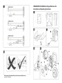
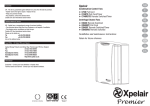
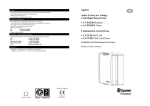
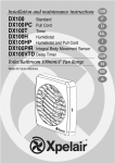
What you will need
need 8..
• To fix these fans through a wall you will need “Wall Vent Kit VK10”.
• To fix these fans through a glass window or panel you will need
“Glass Mounting Kit GMK”
• To fix these fans through a ceiling you will need
"Ceiling Mounting Kit XCMK”.
• A double pole isolating switch with a minimum contact gap of 3mm.
• Suitably rated 3-core or 4-core cable.
• A ceiling or wall on/off switch with built in indicator (DX180T/DX180H)
If installing in a wall (surface mounting)
)
1. Mark on the wall the centre of the duct hole A.
2. Use this centre to cut an opening through the wall Ø117mm,with a
slight fall to the exterior.
3. Fit the wall tube (not supplied) and mortar into place.
)
1. Mark on the wall the centre of the duct hole A, and drill a pilot hole
through both walls at a slight downward angle.
2. Use the centre to mark a rectangular hole for the inner wall using
the dimensions A.
3. Cut the rectangular hole through the inner wall.
4. Go outside and cut a Ø117mm hole in the outer wall using the
small hole as the centre.
5. Measure the wall thickness. Cut the wall tube, not supplied, so that
it is 64mm less than the wall thickness
If installing in a ceiling (surface mounting)
)
This method requires a space above the ceiling, such as a loft or attic,
to provide access for 100mm internal diameter ducting.
1. Mark on the ceiling the centre of the duct hole A, avoiding ceiling
joists and buried cables etc.
2. Cut a Ø117mm hole using the marked centre.
)
For Ø100mm ducting:
1. Mark a rectangular hole using the dimensions B.
2. Cut the hole, avoiding ceiling joists and buried cables etc.
For flat ducting:
• This fan can be installed within a 47mm void without the circular
spigot 6 (Fig.E). Flat ducting adapter (FDA) available.
Preparing the fan for installation
)
1. Assemble the three fan body clamps 8 to the fan box 5 using
suitable screws.
2. Slit the cable grommet. Pass the electrical cables into the fan box 5
through the cable inlet hole and cable grommet.
Ensure cable grommet is in place and a tight fit.
3. Offer the fan box 5 up to the wall.
4. Tighten up the three screws, until the fan is clamped to the inner
wall. The fan body clamps 8 will rotate to an automatic stop
position. DO NOT OVERTIGHTEN.
1. Remove the front cover 1 (Fig.C)
2. Fit the foam tape 9 around the circular spigot 6 (Fig.E).
3. Remove the electrical cover 4 (Fig.E). The impeller 2 can be
removed to aid access (if required). This is a “push-on/pull-off”
assembly.
Mounting the fan in a wall or ceiling (surface mounting)
1. Place the ducting into the hole and align to the required position.
If wall mounting, ensure that the ducting slopes down and way from
the fan
2. Mark the positions of the three fixing holes A in fan box 5 (Fig.E).
3. If wall mounting, drill three holes 5.5mm diameter for wall plugs.
If ceiling mounting B , use suitable fasteners (not supplied).
4. Cut out the cable inlet hole, if required, in the surround10 and slit
the cable grommet. Slide the surround 10 over the fan box 5 .
5. Pass the electrical cables into the fan box 5 through the rear cable
inlet hole and re-fit the cable grommet.
Ensure that cable grommet is in place and a tight fit.
6. Offer the fan box 5 up to the wall or ceiling. Ensure the circular
spigot 6 enters the ducting.
7. Fix the fan box 5 to the wall using suitable screws or to the ceiling
using appropriate fasteners (not supplied).
.
Premier DX180T
.
Premier DX180H
.
• There are no user adjustments for this fan.
)
g
Fit an outer grille to the outer wall.
For ceiling mounting, use appropriate ancillaries.
s
WARNING: THIS APPLIANCE MUST BE EARTHED
n
Premier DX180
• There are no user adjustments for this fan.
1. Insert the fan box 5 into the hole and mark four positions using the
slots in the flange B.
2. Remove the fan box 5 from ceiling and fit four suitable ceiling clips
over the edge of the hole, so that the clips align with the marks on
the ceiling B.
3. Drill 4 pilot holes into the ceiling through the hole of each clip,
ensuring not to damage the clip, and fit the clips ensuring correct
alignment.
4. Fit the ducting to the circular spigot 6.
5. Offer the fan box 5 up to the ceiling.
6. Slit the cable grommet. Pass the electrical cable into the fan box 5
through the front cable inlet hole.
Ensure cable grommet is in place and a tight fit.
7. Using suitable screws 11 (Fig.B), fix the fan box flange to the ceiling
clips.
Wire the electrical connections
.
1. Remove the front cover and replace after adjustment (Fig. C)
The surround 10 is not required.
Terminating the ducting
User adjustments
Before making any adjustments, isolate the fan completely from
the mains supply, check specification below to see which features
apply to your fan.
The surround 10 is not required.
Fit the ducting to the circular spigot 6.
If mounting in a ceiling (flush mounting)
If installing in a wall (flush mounting))
If installing in a ceiling (flush mounting)
If mounting in a wall (flush mounting)
1. Isolate the electricity supply and remove all fuses.
The terminal block will accept cable up to 2.5mm²
2. Use a double-pole isolating switch with a minimum contact gap of
3mm in both poles.
3. Use suitably rated 3-core or 4-core cable dependant on application.
4. Remove the retaining screws of the terminal cover 4, if still in
position.
5. Wire the fan as shown in F using the cable clamp provided. Check
fan model to diagram.
6. Replace the terminal cover 4 and fasten the retaining screws.
7. See section on “User adjustments” if you wish to use settings other
than those that have been factory set.
8. Refit the front cover 1 (Fig.C).
9. Connect the cable from the isolating switch to electrical supply
wiring, and re-check installation.
10. Refit fuses before turning on electricity supply.
11. For fixed wiring circuits, the protective fuse for the appliance must
not exceed 5A.
For Australia Only
Permanently connected to the supply and a remote switch controls
operation. They should be directly wired to the supply through an
approved 10A wall mounted surface switch with at least 3mm
clearance between contacts.
• The humidity setting is adjustable between approximately 50% and
90% relative humidity. Use an electrician’s screwdriver, and turn
screw “RH” (Fig.D), clockwise to increase the relative humidity
setting and anti-clockwise to decrease.
(Note: the fan is more sensitive at 50% RH than at 90% and is
factory set at approximately 70%).
.
Premier DX180
.
Operate the fan using the external on/off switch. Repeat to switch off.
.
Operate the fan using the external on/off switch. Repeat to switch off.
When the switch is turned off, the fan continues to operate for the
over-run timer period. (Fixed at approximately 20 minutes).
g
1. Before cleaning, isolate the fan completely from the mains
supply
2. Only clean the external surface of the fan, using a damp lint free
cloth.
3. Do not use strong detergents, solvents or chemical cleaners
4. Allow fan to dry thoroughly before use.
5. Apart from cleaning, no other maintenance is required
E
Front Cover
Impeller
Screws
Terminal Cover
Fan Box
Circular Spigot
Clamp Screws and Wall Plugs
Fan Body Clamps
Foam Tape
Surround
Ceiling Screws (Diagram B )
Head Office – UK Sales Office and Spares
s
Applied Energy Products Ltd,
Morley Way, Peterborough, PE2 9JJ, England
Tel:
+44 (0) 1733 456789
Fax:
+44 (0) 1733 310606
Sales/Spares Hotline:
+44 (0) 8709 000420
Sales/Spares Faxline:
+44 (0) 8709 000520
Web:
http://www.xpelair.co.uk
s
.
Condensation Operation
The fan operates at condensation control speed, when the relative
humidity exceeds the set level, and turns off when the humidity drops.
1.
2.
3.
4.
5.
6.
7.
8.
9.
10.
11.
e
UK - Xpelair have a comprehensive range of services including:
• Free technical advise Help-Desk from Engineers on all aspects of
ventilation.
• Free design service, quotations and site surveys
Outside UK: See International section below
Please ask for details on:
Tel:
+44 (0) 8709 000430
Fax:
+44 (0) 8709 000530
Guarantee – Contact your local distributor or Xpelair direct
Premier DX180H
Key See Diagram
Technical Advice & Service
International
Switched Operation
The fan can be wired with a separate on/off switch. Fan operates at
condensation speed when switched on. When switched off, the fan will
continue to operate if the humidity level exceeds the set level.
Cleaning
UK: This fan is guaranteed against defects for 2 years from the date of
purchase
• Xpelair reserve the right to repair or replace the fan
• Keep your purchase receipt
• Any problems, contact the address below
Outside UK: See International section below
Also at the address below
Using the fan
Premier DX180T
e
Guarantee
E
IMPORTANT
• READ ALL THESE INSTRUCTIONS & WARNINGS FULLY BEFORE
COMMENCING INSTALLATION.
• INSTALLATIONS AND WIRING MUST CONFORM TO CURRENT IEE
REGULATIONS (UK), LOCAL OR APPROPRIATE REGULATIONS (OTHER
COUNTRIES). IT IS THE INSTALLER’S RESPONSIBILTY TO ENSURE THAT
THE APPROPRIATE BUILDING CODES OF PRACTICE ARE ADHERED TO.
• A QUALIFIED ELECTRICIAN MUST SUPERVISE ALL INSTALLATIONS.
• THESE APPLIANCES ARE INTENDED FOR CONNECTION TO FIXED
WIRING
• CHECK THAT THE ELECTRICAL RATING SHOWN ON THE FAN MATCHES
THE MAINS SUPPLY.
• WARNING: THESE APPLIANCES MUST BE EARTHED.
• SITE AWAY FROM DIRECT SOURCES OF HEAT (I.E.: GAS COOKERS OR
EYE-LEVEL GRILLS) AND NOT WHERE AMBIENT TEMPERATURES ARE
LIKELY TO EXCEED 50 OC.
• WHEN THE FAN IS INSTALLED IN A ROOM CONTAINING A FUEL
BURNING APPLIANCE, PRECAUTIONS MUST BE TAKEN TO AVOID THE
BACKFLOW OF GASES INTO THE ROOM FROM THE OPEN FLUE OF THE
FUEL BURNING APPLIANCE
• ENSURE THAT ALL RELEVANT SAFETY PRECAUTIONS (CORRECT EYE
PROTECTION AND PROTECTIVE CLOTHING ETC) ARE TAKEN WHEN
INSTALLING, OPERATING AND MAINTAINING THIS FAN.
• IF ANY SECTION OF THE DUCTWORK IS POSITIONED HIGHER THAN THE
FAN A CONDENSATION TRAP (XCT100) MUST BE FITTED AS CLOSE AS
POSSIBLE TO THE FAN
• GENERAL GUIDANCE FOR SITING THE FAN SEE “FIG.G”. ALWAYS SITE
FAN AS HIGH AS POSSIBLE
• THE APPLIANCE IS NOT INTENDED FOR USE BY YOUNG CHILDREN OR
INFIRM PERSONS. YOUNG CHILDREN SHOULD BE SUPERVISED TO
ENSURE THEY DO NOT PLAY WITH THE APPLIANCE
FM11408 - QAS 3284/37
PREMIER DX180 RANGE Centrifugal Bathroom Fan
Installation and Operating Instructions
Please leave this leaflet with the fan for the benefit of the user
Leaflet No. 567-2068-04A