1
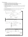
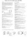
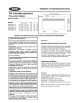
Xvent multipoint ventilation units
Xvent 340 range
Information on Maintenance and Operation
For the Householder
Your home has been fitted with a mechanical ventilation system. The system should consist of a central
mechanical extract fan, ducting, an external exhaust and extract valves in all the wet rooms e.g. the
kitchen, bathroom and toilet. The proper working of the system will provide a healthy indoor atmosphere
and will help eliminate condensation.
The Xvent 340 / Xvent 340DC system is (or can be) fitted with a 3-position switch, while the Xvent
340DCRF system is used in conjunction with a three speed wireless transmitter to set 3 different running
speeds. The high speed setting is a boost position for the extract of cooking smells or moisture-laden air,
when this is in use it is advisable to open window vents or a window to provide replacement air.
The middle position would be the normal running position in a house with the low speed position as a
background position if the house is not fully occupied. In a smaller dwelling or flat the low speed position
could be the normal running position with the middle position as a boost.
The fan is designed to run continuously 24 hours a day. It is fitted with an energy efficient electric motor.
Maintenance
In normal running the design of the fan attracts very little dirt. It may be advisable to have the unit
inspected by your installer once every 4 or 5 years and cleaned if necessary.
For the Installer
If you have any queries before installing these products or after they are installed call the Xpelair
Technical Hotline +44 (0) 8709 000430. Our engineers are there to help during normal office hours
(UK only) and may be faxed at all other times on + 44 (0) 8709 000530.
Customers outside the UK please contact your local Xpelair distributor, details of which are
available from the UK office.
Characteristics
The electric motor and fan are enclosed in the ventilator housing. Attached to the casing are 4, 125 mm
diameter spigots for ductwork connections, 3 for extract ductwork and one common spigot to take the
waste air to atmosphere.
Installation
The installation should minimise resistance and prevent any leakage in the ducting. Where possible the
use of flexible ducting should be avoided. If an extract spigot is not used it should be closed with a cover.
If installing in a position where condensation is likely to run back towards the fan, you will need a
suitable condensation trap.
Position of air intake:
• As far as possible from and opposite to the main source of air replacement to ensure airflow
across the room (e.g. Opposite an internal doorway).
• Near the source of steam or odours.
• Not where ambient temperatures are likely to exceed 50ºC, or above a cooker hob or eye level
grille.
• If installing in a room containing a fuel burning device, it is the installer’s responsibility to
ensure that there is enough replacement air to prevent fumes being drawn down the flue when
the fan is operating up to maximum extract. Refer to Building Regulations for specific
requirements.
• Exhaust air must not be discharged into a flue used foe exhausting fumes from appliances
supplied with energy other than electric. Requirements of all authorities concerned must be
observed for exhaust air discharge.
• The inlet grilles should be situated at least 0.5m distance from the discharge outlet of a flued
heating or cooking appliance.
Position of the air outlet:
• At least 0.5m away from open door or window, or the inlet of another ventilation device.
The fan unit must always be firmly fixed.
This can be done by either of the methods below:
• Using woodscrews fixed through the corner of the ventilator box.
• Using threaded bolts in the notched holes.
Electrical
The Xvent 340 and Xvent 340DC can be wired to run at speed 1, 2 or 3 or by use of a 3-speed switch,
which gives speed choices to the user. The Xvent 340DCRF is to be wired to run at 3 speeds by use of the
RF wireless control system. See section on remote control. For wiring of the ventilation unit see wiring
instructions.
Maintenance
This fan unit requires little maintenance.
Every 4-5 years it is advised to disassemble the unit, remove the motor and impeller assembly and clean
the impeller using soapy water (making sure that water does not get into the motor)
CE-conformity
This unit meets all relevant CE standards.
Removing the cover
Insert a screwdriver in one of the 4 openings in the slanting corners of the box.
Turn the screwdriver so that the corner piece unlocks and loosens the cover.
It may be necessary to unlock more than one corner.
Removing the motor and impeller assembly
Remove the motor and impeller assembly by using the 3 click connections fixed to the casing.
Insert a screwdriver into one of the grooves and turn it until the section becomes free.
When all 3 positions are loosened the motor plate can be removed from the casing.
Reassembly
Place the ventilator unit in the correct position and click the cover back in place.
Wiring Instructions
• This appliance is intended for connection to fixed wiring
• Check that the electrical rating shown on the fan matches the mains supply.
• WARNING: THIS APPLIANCE MUST BE EARTHED
• All installations must be supervised by a qualified electrician.
• Installations and wiring must conform to current IEE Regulations (UK), local or appropriate
regulations (other countries).
• A means for disconnection must be incorporated in the fixed wiring in accordance with the
wiring rules
1.
2.
3.
4.
Switch off the mains electrical supply and remove all fuses before commencing wiring.
Wire the fan as shown below
Connect the cable from the isolating switch to the electrical supply wiring.
Refit fuse before turning on the electricity supply
Remote control – RF – Radio Frequency (868,3MHz)
OPERATION:
The RF system (Radio Frequency) is an installation technique that does not use any
wiring between the control point(s) and the receiver. This technique is known as
“remote control”. Transmission is via radio waves which makes the system ideally
suited for use in specific applications such as renovation of interiors, extensions; in
existing electrical installations where drilling or channeling work is excluded,
offices with movable walls etc, or to avoid the use of complex cabling
configurations. It is a modular system consisting of one or more emitters and one or
more receivers. The emitters take the form of a wall-mount switch. Each emitter can
control an unlimited number of receivers simultaneously. Each receiver can be
controlled by up to 32 emitters.
CHARACTERISTICS:
• emitter range: 100m in open air
• no wiring between control points and receivers (RF controlled), only one
connection between the switch-receiver and the device to be operated.
• orientation of emitters is not necessary. Transmission of signals through non-metal
walls is possible.
• the wall-mount emitter can be readily glued or screwed on the wall.
• receiver and emitter form one integrated whole
• operating temperature: -5°C to +45°C
• receiver: max. load 4A / 230V~ 50Hz
• emitters + base plate: button with 4 positions
= low
= middle
= high
= high with timer
-
short press (<1.6sec.) = max. speed for 10 minutes
long press (>1.6sec.) = max. speed for 30 minutes
After this time has elapsed the fan returns to the lowest position.
MOUNTING INSTRUCTIONS AND RECOMMENDATIONS
• Never mount the emitters and/or receivers in a metal distribution box, housing or
netting.
• Wherever possible, avoid mounting the emitters and/or receivers in the immediate
vicinity of large metal objects.
• Never mount emitters and/or receivers on (or near) the ground.
• Best results are obtained when mounting the receivers as closely to the emitters as
possible.
• The presence of metal or moisture in the walls may adversely affect the emitter
range.
MOUNTING
Test the emitter before mounting!
The RF emitter can be mounted in two ways:
A) Gluing:
Mounting on a flat base, e.g. glass, paint, varnished wood, tiles...
1 Make sure the base is free from dust and grease.
2 Remove the protective strips on the back of the base plate, glue the base plate on
the place where the emitter is to be mounted and press down well (Fig.A).
3 Click the cover plate onto the base plate (Fig.B).
4 Click the emitter unit into the cover plate with the battery pointing upwards
(Fig.C).
5 Remove the protection between the battery and the contacts (Fig.D).
6 Fit the control buttons (Fig F)
B) Screwing:
Mounting on a flush-mounting box on a structured base, e.g. stone walls, plaster...
1 Click the cover plate onto the base plate (Fig.B).
2 Centre the assembly and screw onto the wall using the screws and plugs provided
(Fig.E).
3 Click the emitter unit into the cover plate with the battery pointing upwards
(Fig.C).
4 Remove the protection between the battery and the contacts (Fig.D).
5 Fit the control buttons.
Replacing the battery (Fig.D):
- unscrew battery clamp.
- insert new battery with positive pole pointing towards you.
- screw down battery clamp.
For use in: BE/NL/FR/DE/AT/ES/PT/CH/DK/LU/GR/SL/CZ/NO/GB
Battery equivalents for emitter:
Varta
3V/260mAh CR2430
Panasonic 3V/250mAh CR2330
Putting into service
After installing the emitters and receivers, the emitters must be programmed with
the receivers. A receiver will only work if the address of an emitter has been
programmed in the receiver.
PROGRAMMING
• Using a fine screwdriver, briefly (< 1.6 sec) press the flush programming key
situated on the receiver on the Xvent unit.
• A light signal starts flashing (flashing = 1 sec.).
• Program all (RF) emitters that have to interwork with the receiver one by one. The
correct reception of an address is acknowledged by a long light signal (4sec.).
• Up to 32 emitters can be programmed per receiver. When this maximum is
reached, the LED will keep flashing.
• You can end the programming by briefly (<1.6 sec) pressing the flush key again.
ADDING EMITTERS
Additional emitters (max. 32) can at all times be programmed on a receiver.
Repeat “PROGRAMMING”.
RESET:
• Press the flush key on the receiver (see section “Programming’) for more than 1.6
sec.(flashing LED).
• Press a second time on the flush key >1.6 sec.
• The receiver’s memory is now completely erased. This is acknowledged by a long
light signal (4sec.).
• End RESET by briefly (< 1.6 sec) pressing the flush key.
The programming is not lost in the event of a prolonged power failure.
SELECTIVE ERASE
• Press the flush key on the receiver (> 1.6 sec).
• A light signal starts flashing (flashing LED)
• Press 1 of the control buttons of the emitter that you want to erase
• The emitter is erased from the memory, which is acknowledged by a long light
signal (4sec.)
• End RESET by briefly (<1.6 sec) pressing the flush key again.
IN CASE OF MALFUNCTIONS:
New installation:
• Check that the protection between the battery and the contacts has been removed
in the emitter.
• Check the battery and the contacts for proper permanent contact.
• Reset and program or reprogram the receiver.
• Press the programming key. The receiver is now in programming mode: there is a
flashing light signal and the load is activated; it not, the receiver is defective.
Program the emitters with the receiver and end the programming.
• Emitter malfunction:
Pick up the emitter and walk towards the receiver.
• It the system works when holding the emitter in the hand but not when it is placed
on the wall, this may indicate the presence of moist or metal in the wall. You should
then mount the emitter in another place.
• If the system works at reduced distance, this indicates either that the emitter has
been placed outside the emitter range or an interference problem.
You should then place the emitter closer to the receiver or outside the reach of the
interference.
• The system does not work even after placing it closer to the receiver.
You should then check the programming and/or the battery of the emitter (see
above)
Existing installation
• Check the batteries of the emitter(s)
• Check the operation of the connected receivers
• Check for interference caused by changes in the system environment (metal
cabinets, walls or furniture moved....)
Restore the original condition.
The system automatically switches on and off.
a. The system automatically switches on: This is only possible if a foreign emitter
previously programmed in the receiver is operated within the receiver range. Reset
the receiver and reprogram the relevant addresses (see Programming).
b. The system automatically switches off: This situation may be similar to point a)
or may be the result of transient power cuts.
Do’s and dont’s
• Do read all the instruction leaflet before commencing installation
• Do install each fan with a double pole isolating switch.
• Do make sure the mains supply is switched off before attempting to make electrical
connections or carry out any maintenance or cleaning
Guarantee
Customers outside UK – see international below.
• UK: The Xvent 340 is guaranteed against defects for 3 years from the date of purchase.
• UK: The Xvent 340DC / Xvent 340DCRF is guaranteed against defects for 5 years from the
date of purchase.
• Please keep your purchase receipt.
• If you have any problems, contact Xpelair’s Head Office at the address shown below.
Technical advice and service
Customers outside UK – see international below.
UK: Xpelair have a comprehensive range of services including:
• Free technical advice help -desk from Engineers on all aspects of ventilation
• Free design service, quotations and site surveys
• Service and maintenance contracts to suit all requirements.
Please ask for details:
• By telephone on Techline :+44 (0) 8709 000430
• By fax on Techfax :+44 (0) 8709 000530
• At the address below
International
• Guarantee: Contact your local distributor or Xpelair direct for details
• Technical Advice and Service: Contact your local Xpelair distributor
Technical
Applied Energy Products Ltd
Morley Way
Peterborough
advice
and service
PE2 9JJ
t 01733 456789
f 01733 310606
www.applied-energy.com
Xpelair is a registered trademark of Applied Energy Products Limited.
Applied Energy Products reserve the right to alter product specifications
or appearance without prior notice. All finishes and diagrams in this
booklet are as accurate as printing processes allow.