1
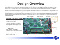
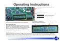
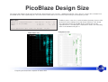
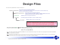
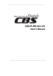
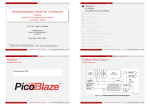
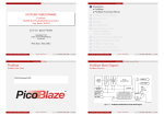
Frequency Generator
for
Spartan-3E Starter Kit
Ken Chapman
Xilinx Ltd
18th July 2006
With special thanks to
Peter Alfke and Alireza Kaviani.
Rev.1
Limitations
Limited Warranty and Disclaimer. These designs are provided to you “as is”. Xilinx and its licensors make and you receive no
warranties or conditions, express, implied, statutory or otherwise, and Xilinx specifically disclaims any implied warranties of
merchantability, non-infringement, or fitness for a particular purpose. Xilinx does not warrant that the functions contained in these
designs will meet your requirements, or that the operation of these designs will be uninterrupted or error free, or that defects in
the Designs will be corrected. Furthermore, Xilinx does not warrant or make any representations regarding use or the results of
the use of the designs in terms of correctness, accuracy, reliability, or otherwise.
Limitation of Liability. In no event will Xilinx or its licensors be liable for any loss of data, lost profits, cost or procurement of
substitute goods or services, or for any special, incidental, consequential, or indirect damages arising from the use or operation
of the designs or accompanying documentation, however caused and on any theory of liability. This limitation will apply even if
Xilinx has been advised of the possibility of such damage. This limitation shall apply not-withstanding the failure of the essential
purpose of any limited remedies herein.
This design module is not supported by general Xilinx Technical support as an official Xilinx Product.
Please refer any issues initially to the provider of the module.
Any problems or items felt of value in the continued improvement of KCPSM3 or this reference design would be gratefully
received by the author.
Ken Chapman
Senior Staff Engineer – Spartan Applications Specialist
email: [email protected]
The author would also be pleased to hear from anyone using KCPSM3 with information about your application and PicoBlaze
has been useful.
Frequency Generator for the Spartan-3E Starter Kit 2
Design Overview
This design converts the Spartan-3E Starter Kit into a reasonably accurate frequency generator covering the nominal range 1Hz to 100MHz. The design
allows you to attempt generation of higher frequencies to allow you to experiment with the maximum performance of the Spartan device on your board. The
rotary control is used to edit the frequency displayed on the upper line of the LCD display and the corresponding frequency will then be output on the SMA
connector (J17) as well as the stake pin J4-IO12. Internally to the device the frequency range is twice that provided externally (nominally up to 200MHz).
As well as providing the basic instructions to use the frequency counter, this document provides details of the Direct Digital Synthesis (DDS) techniques used
in the design such that the can be transplanted into your own designs. PicoBlaze is used to provide the human interface and perform so high precision
calculations which are passed to a simple but high performance (200MHz) frequency synthesizer formed from pure hardware and two Digital Clock Managers
(DCMs). The lower line of the LCD display provides the information passed from PicoBlaze to the hardware which means that you can use this design with
your board to determine the exact values required to implement a fixed frequency synthesizer without requiring PicoBlaze, the knob and LCD display. On this
board the technique provides a convenient alternative to fitting a special oscillator in the IC16 socket and it may proves a cost effective solution for many real
product applications too.
Output Frequency provided on
50MHz Reference
SMA socket
Spartan XC3S500E
Crystal Oscillator
Load it now – it only takes 30 seconds!
It is recommended that you try this to become
familiar with what the design does (operating
instructions on the next page).
As well as the source design files, a compiled
configuration bit file is provided which you can
immediately download into the Spartan
XC3S500E device on your board. To make this
task really easy the first time, unzip all the files
provided into a directory and then….
double click on
‘install_frequency_generator.bat’.
Assuming you have the Xilinx software installed,
your board connected with the USB cable and
the board powered (don’t forget the switch),
then this should open a DOS window and run
iMPACT in batch mode to configure the
Spartan-3E with the design.
J4-IO9
Phase
Accumulator
Test Point
J4-IO12
Copy of Output
Frequency
LEDs indicate
frequency
editing mode
Press and rotate knob
to set frequency
Frequency Generator for the Spartan-3E Starter Kit 3
DDS control values
(bottom line)
Frequency display
(top line)
Operating Instructions
Output frequency provided on SMA connector (J17)
and J4_IO12.
LEDs indicate the editing mode.
= Edit cursor position mode
= Edit digit value mode
Press and release knob to toggle between frequency editing modes
The cursor can be moved into the
10MHz and 100MHz digit positions but
these positions are blanked when zero.
The cursor is the small
black line under the digit
in the top line.
Edit cursor position mode
In this mode rotating the knob to the left or right will cause the display
cursor to move in the corresponding direction on the upper line of the
display. Use this mode to position the cursor below the digit you wish to
adjust and then press and release the knob to change mode. The
cursor automatically skips past the decimal point and space separator
and hits ‘end stops’ if you over rotate the knob.
Edit digit value mode
In this mode rotating the knob to the left or right will decrement or increment the value of the digit located at the cursor position. The controller will
automatically borrow from, or carry to, the more significant digits to the left of the digit being adjusted. Every adjustment will immediately result in the
corresponding frequency change at the output which is also reflected by the changes to the computed DDS control values on the lower line of the display.
Press and release the knob to revert to cursor position mode when complete.
Frequency Generator for the Spartan-3E Starter Kit 4
PicoBlaze Design Size
The images and statistics on this page show that the design occupies just 172 slices, 1 BRAM and 2 DCMs. This is only 3.7% of the slices available in an
XC3S500E device. More significantly, this slice count can be reduced to less than 32 when implementing a fixed frequency version.
MAP report
Number of occupied Slices:
Number of Block RAMs:
DCMs:
172 out of
1 out of
2 out of
Total equivalent gate count for design:
4,656
20
4
3%
5%
50%
PicoBlaze makes extensive use of the distributed memory features of the
Spartan-3E device leading to very high design efficiency. If this design
was replicated to fill the XC3S500E device, it would represent the
equivalent of over 1.5 million gates. Not bad for a device even marketing
claims to be 500 thousand gates
91,537
FPGA Editor view
XC3S500E
Frequency Generator for the Spartan-3E Starter Kit 5
Floorplanner view
Design Files
The source files provided for the reference design are…..
frequency_generator.vhd
Top level file and main description of hardware.
Contains I/O required to disable StrataFLASH memory device on the board which may
otherwise interfere with the LCD display.
frequency_generator.ucf
kcpsm3.vhd
fg_ctrl.vhd
I/O constraints file for Spartan-3E Starter Kit
Timing specifications for 50MHz PicoBlaze controller 200MHz DDS circuits.
Location constraint for DCM used for Jitter reduction.
PicoBlaze processor for Spartan-3E devices.
Assembled program for PicoBlaze (stored in a Block memory)
fg_ctrl.psm
PicoBlaze program source assembler code
This design contains an otherwise undocumented and unspecified mode of
operation for a DCM. Before this design can be processed a special BITGEN option
needs to be set. Please read the notes provided on page 13 as well as those
contained in ‘frequency_generator.vhd'for details of this special requirement.
Note: The file shown in green is not included with the reference design as it is provided with PicoBlaze download. Please visit the PicoBlaze Web site
for your free copy of PicoBlaze, assembler, JTAG_loader and documentation.
www.xilinx.com/picoblaze
Hint – The JTAG_Loader utility supplied with PicoBlaze has been included in this design. This enables the new programs to be written for PicoBlaze
using the configuration file provided.
Hint – You do not need PicoBlaze if you use this design as the basis for implementing a fixed frequency module. However, I’m sure you will want
PicoBlaze for other parts of your design now that you have seen what it is capable of doing .
Frequency Generator for the Spartan-3E Starter Kit 6
Direct Digital Synthesis (DDS) Circuit Diagram
io12
31
frequency_divider[31:0]
The phase accumulator is a standard 32-bit accumulator operating at 200MHz. This accumulator is
really the heart of the DDS as it is the most significant bit of the accumulator that produces the
variable frequency being synthesized. The remaining circuits only multiply, divide and clean this
synthesized frequency or are involved with selecting and generating the DDS control words.
30
29
The frequency of the most significant bit is defined by the 32-bit value applied to the input of the
3
accumulator. This value is shown as ‘N’ on the LCD display and is applied to the bus
2
‘dds_control_word’ in the circuit. The value of N is computed in such a way that the synthesized
1
freq_scaling
frequency is nominally in the range 6.25MHz to 12.5MHz so that it is always a suitable
0
input to the second DCM.
32-Bit
Counter
dds_scaling_word
N × 200MHz
FMSB =
D
232
In this example N=204010946 decimal so the output from the phase accumulator
is ~9.5MHz (a period of approximately 105ns). That means that the accumulator
synthesizes one output cycle for approximately 21 cycles of the 200MHz clock
from which the accumulator runs.
io9
N
[31]
dds_control_word[31:0]
FO =
frequency_aligned_dcm
DCM
phase_acc_dcm
50MHz
DCM
clk
BUFG
200MHz
CLKIN
×4
CLKFX
CLKFX_MULTIPLY=4
clk_200mhz
dds_clk
BUFG
CLKFX_DIVIDE=1
The first DCM is used to multiply the 50MHz clock by a
factor or 4 and form a 200MHz clock. This gives the
phase accumulator a timing resolution of 5ns.
Frequency Generator for the Spartan-3E Starter Kit 7
CLKIN
×16
CLKFX
CLKFX_MULTIPLY=256
+
A simple binary counter is used
to divide the low jitter clock by
powers of 2 and a multiplexer
selects the appropriate course
division factor.
synth_clk
phase_accumulator[31:0]
phase_acc
sma_out
CLKFX_DIVIDE=16
dcm_clean_clk
BUFG
N × 200MHz × 16
2(D+1) × 232
In the example, D=4 so the
~153MHz from the DCM is
divided by 2(4+1)=32
FO=4.7499999869MHz
The second DCM is used in a ‘frequency aligned mode’. At the time of writing this
reference design, this mode is not an officially documented or supported feature.
However, it is hoped that this reference design will enable you to see this mode in action
and evaluate it for yourself. In this mode, the DCM not only multiplies the input clock, but
also has the effect of reducing cycle to cycle jitter. This is because the normal phase
alignment mode of the DCM has been disabled and the DCM is tracking the average of
the input frequency instead.
In the example, the input to the DCM will have 5ns
of cycle to cycle jitter as the square wave is formed
from 21 cycles of 200MHz. The DCM will generate
10 or 11
10 or 11
~153MHz square wave with <300ps of jitter.
cycles
cycles
PicoBlaze Circuit Diagram
led(2)
led(1)
7
led(0)
proc_reset
JTAG
bidirectional
LCD data
clk
input_ports
rotary_press_in
processor
instruction
address
write_strobe
kcpsm3
lcd(7)
address
instruction
address
kcpsm3_reset
instruction
lcd(4)
lcd(6)
lcd(5)
lcd(4)
out_port
in_port
out_port
in_port
0
read_strobe
clk
read_strobe
lcd_e
6
port_id
port_id
clk
interrupt
lcd_rs
lcd_rw
write_strobe
reset
interrupt
interrupt_ack
5
[4:0]
clk
dds_scaling_word
D
interrupt_control
rotary_filter & direction
rotary_b
led(3)
fg_ctrl
lcd(5)
rotary_a
output_ports
program_rom
lcd(6)
See reference
design called
‘Rotary Encoder
Interface for
Spartan-3E Starter
Kit’ for details of
this section.
led(5)
‘JTAG_loader’ allows rapid
PicoBlaze code development.
Hint – The ‘fg_ctrl.psm’ file contains significant
comments to explain the operations and calculations
that the PicoBlaze program is performing to
generate ‘N’ and ‘D’ from the BCD value displayed
on the LCD.
lcd(7)
50MHz clock to all items on this page
led(6)
led(4)
PicoBlaze provides the user interface and performs
the calculations required to generate the 32-bit DDS
control word ‘N’ and 5-bit DDS scaling word ‘D’.
rotary_press
led(7)
4
[31:24]
rotary_left
interrupt_ack
rotary_event
[23:16]
dds_control_word
Vcc
strataflash_oe
strataflash_ce
strataflash_we
Frequency Generator for the Spartan-3E Starter Kit 8
3
* StrataFLASH memory
must be disabled to
* prevent interference with
* the LCD display.
*
2
1
[15:8]
[7:0]
N
Phase Accumulator Waveforms
The following waveforms were obtained by monitoring the output of the phase accumulator presented on stake pin ‘J4-IO9’. In each case the digital storage
oscilloscope was set to infinite persistence in order capture any fluctuations over time and therefore observe the ‘envelope’ of operation.
This waveform shows a pretty clean 12.5MHz square wave. The reason the waveform is so
clean is because 12.5MHz is a perfect division of the 200MHz clock used by the phase
accumulator and it means that the synthesized waveform is always formed of 16 clock periods
of the 200mHz clock with 8 Low and 8 High.
12.5MHz
8 cycles
8 cycles
@ 200MHz @ 200MHz
16 cycles
@ 200MHz
Note that to force this frequency at the phase accumulator I actually dialled in a frequency of
100MHz on to the LCD display such that N=10000000 hex.
This waveform shows what happens when you try to synthesize a 12.4125MHz clock using the
phase accumulator. There is clearly 5ns of cycle to cycle jitter in this situation because each
output cycle really should be formed of ~16.113 periods of the 200MHz clock which is
impossible. Therefore what the phase accumulator is doing is to provide the correct average
frequency by making some cycles of 16 periods and then make approximately 1 in every 9
cycles have 17 periods; a mix of 12.5MHz and 11.767MHz waveforms.
16 cycles
@ 200MHz
17 cycles
@ 200MHz
Note that to force this frequency at the phase accumulator I actually dialled in a frequency of
99.3MHz on to the LCD display such that N=0FE353F7 hex
5ns of cycle to cycle jitter is often acceptable when synthesizing lower frequencies especially if the waveform is only used as a digital clock for control and
timing of slower events. However, for higher frequencies such jitter becomes acceptable (i.e. at 100MHz the cycle period is only 10ns).
Frequency Generator for the Spartan-3E Starter Kit 9
Phase Accumulator Spectrum
An alternative way to observe the quality of the waveforms synthesised by the phase accumulator is to look at the frequency spectrum. I was lucky enough
to have a 2048-point FFT feature on my oscilloscope which allows some simple observations to be made. Once again I have set the display to infinite
persistence in order capture the spectrum over a long period of time (>15 seconds). I suggest that you do not look for exact values, but compare the plots
which have been captured using the same scales in each case. On the left are plots that show the spectrum up to 50MHz and on the right the plots show
are zoomed in to show ±5MHz centred on 12.5MHz.
12.5MHz
Fundamental
3rd
Harmonic
As we know the 12.5MHz signal is
nominally clean in terms of the synthesis
process and this is reflected by a distinct
12.5MHz component which is >45dB above
the noise floor. The zoomed plot shows how
the fundamental covers only a narrow
bandwidth keeping in mind that the
resolution of the FFT is only ~50KHz.
12.5MHz
Fundamental
Note the third harmonic of a square wave is
also very distinct at 37.5MHz and is even
close to being the theoretical 9.54dB down
from the fundamental (1/3 amplitude).
5MHz/division
10dB/division
12.4125MHz
Fundamental
1MHz/division
10dB/division
When we move to the less than perfect
12.4125MHz waveform the effects of that
5ns of cycle jitter and jumping between
12.5MHz and 11.76MHz waveforms is
obviously having an impact on the
spectrum. Although the fundamental
frequency component is good, if a little
wider in bandwidth, there are significant
modulation effects leading to a family of
spectral components and raised noise floor.
Hint – 12.5MHz-11.76MHz = 0.74MHz
Frequency Generator for the Spartan-3E Starter Kit 10
12.4125MHz
Fundamental
12.4125±0.74MHz
Final Output Waveforms
These waveforms were obtained from stake pin ‘J4-IO12’ and reflect the final output of the frequency generator. Once again the digital storage
oscilloscope was set to infinite persistence in order capture any fluctuations over time and therefore observe the ‘envelope’ of operation.
In these cases the frequency shown on the LCD display directly corresponds to the frequency
provided at the output. However it is useful to understand what the phase accumulator is
generating to appreciate if the second DCM in ‘frequency aligned mode’ is helping.
For this 12.5MHz waveform N=08000000 hex and D=02 hex. So in fact the phase accumulator
is synthesizing 6.25MHz. This is again a perfect division of the 200MHz clock and means that
the synthesized waveform is always formed of 32 clock periods with 16 Low and 16 High. There
is therefore no obvious cycle jitter introduced and therefore it is not surprising that the final
output (6.25MHz × 16 / 2(2+1) = 12.5MHz) is also nice and clean.
You may have to look closely to notice that this second plot really is 12.4125MHz. It is immediately
clear that there is no obvious cycle to cycle jitter present. To confirm that this isn’t just a
coincidence, we must again consider what the phase accumulator is doing at the same time.
With 12.4125MHz set, N=0FE353F7 hex and D=03 hex. So in fact the
phase accumulator is actually synthesizing 12.4125MHz as well. More
significantly, it means that the phase accumulator is generating
exactly the same waveform as we observed previously on page 9 in
which there was 5ns of cycle to cycle jitter present (see right).
Phase Accumulator
The final output (12.1425MHz × 16 / 2(3+1) = 12.1245MHz) shows that the frequency aligned
mode of the DCM is tracking the average frequency of the input waveform and totally ignoring
the phase of the input waveform resulting in a very low cycle to cycle jitter. In fact the DCM is
only using the frequency information from the input waveform and the output cycle jitter is totally
independent of the input cycle jitter.
Hint – When using a DCM in frequency aligned mode, you must accept that it does NOT maintain phase lock as it does in all other ‘normal’ modes. More
significantly the output frequency is the average of the input frequency which means there will often be a slight difference as it tracks the input.
Frequency Generator for the Spartan-3E Starter Kit 11
Final Output Spectrum
Observing the frequency spectrum of the final output reveals that you can not get something for nothing and helps us to understand when the frequency
aligned mode should and should not be used. I have used the infinite persistence display again and this time it was even more useful to do so. As before,
plots on the left cover up to up to 50MHz and on plots on the right show ±5MHz centred on 12.5MHz.
12.5MHz
Fundamental
3rd
Harmonic
These plots show that the 12.5MHz signal is
actually not as good as that generated
directly at the output of the phase
accumulator. Although clearly centred at
12.5MHz the spectrum shows that there is
an increased bandwidth. This reflects that
the DCM is tracking the input frequency
even though it doesn’t really need to do
anything. It is rather like balancing on a wall;
we know the wall isn’t moving but we still
wobble a bit to stay balanced because we
are unable to freeze completely due to other
influences on us and the need to breath etc!
5MHz/division
10dB/division
12.4125MHz
Fundamental
12.5MHz
Fundamental
1MHz/division
10dB/division
The full spectrum of the 12.4125MHz case
shows how the previous ‘family of spectral
components’ associated with the 5ns of cycle
jitter have been removed and that the noise
floor has been returned to normal levels. The
zoomed plot now shows a fundamental with
what looks like modulation sidebands rather
than fixed spectral components at ±0.74MHz.
This again reflects average frequency
tracking as well as the removal of the 5ns
cycle jitter. Note that an agile frequency
component has a lower energy (W/Hz) than a
static component.
12.4125MHz
Fundamental
±1.3MHz
Hint – If you can synthesize a perfect waveform with a phase accumulator or other direct clock division circuit then it does NOT make sense to use a DCM in
frequency aligned mode. In all non integer division cases the DCM will dramatically help jitter performance but some frequency ‘tracking’ must be accepted.
Frequency Generator for the Spartan-3E Starter Kit 12
Setting DCM Frequency Aligned Mode
To set the DCM into the frequency aligned mode of operation a special option must be used during configuration file generation. This can be set in the ISE
tools as shown in these screen shots from an ISE v8.1i project for this reference design.
1) In the ‘Processes’ window select ‘Generate Programming File’. Then
right click and select ‘Properties’ to open the ‘Process Properties’ box.
2) The ‘Process Properties’ box should open with the ‘General Options’ being
shown (otherwise select ‘General Options’ on the left). Move to the line ‘Other
Bitgen Command Line Options’ and enter the text string shown below.
Hint – You may need to set ‘Property display level’ to ‘Advanced’ and scroll down
to see this line.
3) Select ‘Apply’ and then use ‘OK’ to exit the box.
Hint – Reopen the box and confirm the option really was set correctly.
Hint – The format of this special DCM
option are described in some detail in
the ‘frequency_generator.vhd’ file from
which you can also copy and paste to
avoid typing errors!
-g cfg_dfs_s_x1y1:1111000011111111xxx111xxxxx1xxxxxxxxxx1xxxxxxxxxxxxxxxxxxxxxxxxxxxxx01000000
Frequency Generator for the Spartan-3E Starter Kit 13
Exercises, Experiments and Suggestions
Here are some exercises, experiments and suggestions for you to consider based on this reference design. Although several are specific to the Spartan3E Starter Kit, most are portable to your own boards and designs where I hope you will find the design concept useful.
Turn it off!
Probably the best way to convince yourself that the frequency aligned mode of the DCM is really doing something special is to turn it off (remove the
special BITGEN option) and then look at the output waveform on an oscilloscope particularly at frequencies >50MHz.
How fast is yours?
The PicoBlaze controller does not limit the upper frequency that you can enter to see how high the frequency is that your board can generate.
Hint 1 – Although the display supports up to 999MHz, the largest valid value you can enter is 212.499999MHz because this sets N=0FFFFFEA.
Hint 2 – The output from the second DCM is always divided by at least 2 before it reaches the output pin, so internally a clock can be faster.
Hint 3 – As you increase the frequency you will reach the limit of I/O performance. Experiment with increasing output drive strengths and FAST slew rates.
Save Oscillators and Save $
This reference design could be the way to save money by replacing a set of different crystal oscillators required to support multiple standards etc. This
design together with the board allows you to directly try the output with your own products and see if it works for you. The plots shown in this document
clearly show that the final output has very low cycle to cycle jitter compared with the output from a phase accumulator DDS circuit. However, it is also
shown that the output still has some additional frequency components as it tracks the average frequency. In some applications this will have no effect
whilst others may find it an issue. Some applications can actually benefit from the partial spread spectrum effect (i.e. reduced EMC).
Fixed Frequency Modules
If you know which frequencies you require, then reduce the design to a phase accumulator driven by a constant ‘N’, the DCMs and a fixed counter divider
(no multiplexer).
Hint – If you still operate the phase accumulator at 200MHz, then use the supplied design on the board to calculate your ‘N’ and ‘D’ values for you.
Hint – Remember to share the 200MHz fast clock between several phase accumulators to save DCMs.
Accurate Measurements
If you have access to superior measurement equipment, then measure the frequency generator output for yourself and observe the tracking nature of the
output. Be careful not to confuse I/O and PCB effects with what you are attempting to measure using such good equipment.
Simple Frequency Measurements using the Spartan-3E Starter Kit
Create a fixed frequency version of the design for a frequency of your choice. Then insert that module into the reference design called ‘PicoBlaze
Frequency Counter for the Spartan-3E Starter Kit Board’ in place of one of the existing sources so that you can observe the output frequency.
Hint – The output frequency should be correct, but you should be observing a variation above and below as the DCM tracks the average frequency value.
Design Throttling
This term is given to the concept of changing the frequency depending on the demands of an application over time. This is a way to save power since
power consumption is directly proportional to operating frequency. The frequency aligned mode allows you to switch between frequencies without causing
glitches and you can prove this with the design provided.
Hint – Increasing ‘CCount’ (read notes in ‘frequency_generator.vhd’) will provide very smooth but relatively slow rates of change in frequency.
Frequency Generator for the Spartan-3E Starter Kit 14