1
BD9:AL&-',
*=E=:6KN"9JINH=6E:G
DLC:GHB6CJ6A
;DGBD9:AHB6CJ;68IJG:9H>C8:($&'
E]dcZ/(+%,()"()-'Dca^cZIZX]c^XVaHjeedgi/iZX]"hjeedgi5h]de[dm#W^o
8DENG><=I6J<JHI!'%&'7NLDD9HID8@>CI:GC6I>DC6A!>C8#
L6GC>C</CDEDGI>DCD;I=>HB6CJ6AB6N7:G:EGD9J8:9>C6CNH=6E:DG;DGBL>I=DJI
I=:LG>II:C6EEGDK6AD;LDD9HID8@>CI:GC6I>DC6A!>C8#
IH&).-)Eg^ciZY^cIV^lVc
K_`jdXelXcgifm`[\jZi`k`ZXcjX]\kp`ejkilZk`fejfek_\gifg\ij\klg#
fg\iXk`fe#dX`ek\eXeZ\#Xe[j\im`Z\f]k_`jdXZ_`e\&kffc%JXm\k_`j
[fZld\ek#i\]\ikf`kf]k\e#Xe[lj\`kkf`ejkilZkfk_\ifg\iXkfij%
=X`cli\kfi\X[#le[\ijkXe[Xe[]fccfnk_\`ejkilZk`fej`ek_`jdXelXc
dXpi\jlck`e]`i\fij\i`fljg\ijfeXc`ealipÇ`eZcl[`e^XdglkXk`fe#
\c\ZkifZlk`fe#fi[\Xk_%
K_\fne\if]k_`jdXZ_`e\&kffc`jjfc\cpi\jgfej`Yc\]fi`kjjX]\lj\%
K_`ji\jgfej`Y`c`kp`eZcl[\jYlk`jefkc`d`k\[kfgifg\i`ejkXccXk`fe`e
XjX]\\em`ifed\ek#g\ijfee\ckiX`e`e^Xe[ljX^\Xlk_fi`qXk`fe#
gifg\i`ejg\Zk`feXe[dX`ek\eXeZ\#dXelXcXmX`cXY`c`kpXe[Zfdgi\$
_\ej`fe#Xggc`ZXk`fef]jX]\kp[\m`Z\j#Zlkk`e^&jXe[`e^&^i`e[`e^kffc
`ek\^i`kp#Xe[k_\ljX^\f]g\ijfeXcgifk\Zk`m\\hl`gd\ek%
K_\dXel]XZkli\in`ccefkY\_\c[c`XYc\]fi`ealipfigifg\ikp
[XdX^\]ifde\^c`^\eZ\#`dgifg\ikiX`e`e^#dXZ_`e\df[`]`ZXk`fejfi
d`jlj\%
Jfd\[ljkZi\Xk\[Ypgfn\ijXe[`e^#jXn`e^#^i`e[`e^#[i`cc`e^#Xe[
fk_\iZfejkilZk`feXZk`m`k`\jZfekX`ejZ_\d`ZXcjbefnekfk_\JkXk\f]
:Xc`]fie`XkfZXlj\ZXeZ\i#Y`ik_[\]\Zkjfifk_\ii\gif[lZk`m\_Xid%
Jfd\\oXdgc\jf]k_\j\Z_\d`ZXcjXi\1
C\X[]ifdc\X[$YXj\[gX`ekj%
:ipjkXcc`e\j`c`ZX]ifdYi`Zbj#Z\d\ekXe[fk_\idXjfeipgif[lZkj%
8ij\e`ZXe[Z_ifd`ld]ifdZ_\d`ZXccp$ki\Xk\[cldY\i%
Pflii`jb]ifdk_\j\\ogfjli\jmXi`\j#[\g\e[`e^fe_fnf]k\epfl
[fk_`jkpg\f]nfib%Kfi\[lZ\pfli\ogfjli\kfk_\j\Z_\d`ZXcj1
Nfib`eXn\ccm\ek`cXk\[Xi\X#Xe[nfibn`k_Xggifm\[jX]\kp\hl`g$
d\ek#jlZ_Xjk_fj\[ljkdXjbjk_XkXi\jg\Z`Xccp[\j`^e\[kf]`ck\i
flkd`ZifjZfg`ZgXik`Zc\j%
J8=<KP%%%%%%%%%%%%%%%%%%%%%%%%%%%%%%%%%%%%%%%%%%%%%%%Standard Machinery Safety Instructions ...... 6
Additional Safety for Shapers .................. 8
G8IKJ%%%%%%%%%%%%%%%%%%%%%%%%%%%%%%%%%%%%%%%%%%%%%% +.
Cabinet .......................................... 47
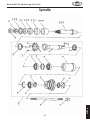
Spindle ........................................... 49
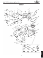
Motor ............................................. 51
Fence ............................................. 53
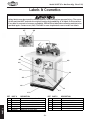
Labels & Cosmetics ............................ 54
N8II8EKP%%%%%%%%%%%%%%%%%%%%%%%%%%%%%%%%%%%%%%%% ,.
FG<I8K@FEJ
D8@EK<E8E:<
FG<I8K@FEJ%%%%%%%%%%%%%%%%%%%%%%%%%%%%%%%%%%%%%%% (0
General .......................................... 19
Control Panel ................................... 19
Cutter Height ................................... 20
Operation Overview ........................... 21
Stock Inspection & Requirements ........... 21
Changing Spindle Speeds ...................... 22
Installing Spindle ............................... 23
Cutter Rotation Direction ..................... 24
Cutter Installation ............................. 24
Hold-Downs...................................... 27
Fence Positioning............................... 28
Straight Shaping ................................ 29
Shaping End Grain .............................. 30
Freehand Shaping .............................. 31
Templates ....................................... 32
Zero Clearance Fence ......................... 33
Box Guard ....................................... 34
Feather Boards ................................. 34
J<IM@:<%%%%%%%%%%%%%%%%%%%%%%%%%%%%%%%%%%%%%%%%%%%% *0
General .......................................... 39
Fence Board Alignment........................ 39
Pulley Alignment ............................... 40
Spindle Bearings ................................ 41
Resurfacing Fence .............................. 41
Spindle-to-Table Squaring..................... 42
Troubleshooting................................. 43
Electrical Safety Instructions................. 45
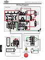
Wiring Diagram ................................. 46
J<KLG
J<KLG%%%%%%%%%%%%%%%%%%%%%%%%%%%%%%%%%%%%%%%%%%%%%% ((
Inventory ........................................ 11
Machine Placement ............................ 12
Cleaning Machine............................... 12
Assembly ......................................... 13
Table Insert Adjustment ....................... 17
Dust Collection ................................. 17
Test Run.......................................... 18
D8@EK<E8E:<%%%%%%%%%%%%%%%%%%%%%%%%%%%%%%%%%%%% *General .......................................... 36
Table & Base .................................... 36
Lubrication ...................................... 37
V-Belt Tensioning & Replacement ........... 38
<C<:KI@:8C
<C<:KI@:8C%%%%%%%%%%%%%%%%%%%%%%%%%%%%%%%%%%%%%%%%%0
Circuit Requirements ............................ 9
Grounding Requirements ...................... 10
Extension Cords ................................ 10
8::<JJFI@<J%%%%%%%%%%%%%%%%%%%%%%%%%%%%%%%%%%%%%% *,
Shaper Accessories ............................. 35
J8=<KP
@EKIF;L:K@FE%%%%%%%%%%%%%%%%%%%%%%%%%%%%%%%%%%%%%)
Woodstock Technical Support .................. 2
Controls & Features ............................. 3
Machine Specifications .......................... 4
@EKIF;L:K@FE
:fek\ekj
J<IM@:<
G8IKJ
LJ<K?<HL@:B>L@;<G8><C89<CJKFJ<8I:?FLK@E=FID8K@FE=8JK
@EKIF;L:K@FE
Df[\cN(/).=fiDXZ_`e\jD]^%J`eZ\*&()
@EKIF;L:K@FE
Nff[jkfZbK\Z_e`ZXcJlggfik
Woodstock International, Inc. is committed to customer satisfaction. Our intent with this manual is to
include the basic information for safety, setup, operation, maintenance, and service of this product.
In the event that questions arise about your machine, please contact Woodstock International Technical
Support at *-' .*+$*+/) or send e-mail to: k\Z_$jlggfik7j_fg]fo%Y`q. Our knowledgeable staff will
help you troubleshoot problems or process warranty claims.
If you need the latest edition of this manual, you can download it from _kkg1&&nnn%j_fg]fo%Y`q.
If you have comments about this manual, please contact us at:
Nff[jkfZb@ek\ieXk`feXc#@eZ%
8kke1K\Z_e`ZXc;fZld\ekXk`feDXeX^\i
G%F%9fo)*'0
9\cc`e^_Xd#N80/)).
<dX`c1dXelXcj7nff[jkfZb`ek%Zfd
-2-
@EKIF;L:K@FE
Df[\cN(/).=fiDXZ_`e\jD]^%J`eZ\*&()
:fekifcj=\Xkli\j
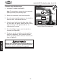
2-Piece Independently
Adjustable Fence
Adjustable
Safety Guard
Workpiece
Hold-Down
Dust
Port
Spindle
Lock
Motor Cover
Spindle
Height Scale
Power Connection
Junction Box
Control
Panel
Spindle Height
Handwheel
=`^li\(% Model W1827 controls and features.
=fiPfliFneJX]\kpI\X[@ejkilZk`feDXelXc9\]fi\
Fg\iXk`e^J_Xg\i
N\Xi\p\gifk\Zk`fe%
9\jli\b\p\[nXj_\i`j[`i\Zkcple[\ijg`e[c\
elkXe[jg`e[c\elk`jk`^_k%
=\\[nfibg`\Z\X^X`ejkifkXk`fef]Zlkk\i%
;fefklj\XnbnXi[_Xe[gfj`k`fej%
B\\g]`e^\ijXnXp]ifdjg`ee`e^Zlkk\i2lj\
]`okli\jfia`^jn_\ee\Z\jjXip%
Lj\fm\i_\X[^lXi[n_\eX[aljkXYc\]\eZ\`j
efk`egcXZ\%
-3-
@EKIF;L:K@FE
Df[\cN(/).=fiDXZ_`e\jD]^%J`eZ\*&()
02'(/:
6+23)2; +36+$3(5
!"#$%!"' ()*(*)"(*")(
+$/"! "
;< =$
= >
/""' )>"(>")(
?$@KN$Q >U>'X
QNQ=$NX (>Y
? N[N\]*\++^Q$</_$$+$?$*@_$
?U >U
N`N ]
;< ;^+==$$`N
'$?$ U >U
YQ Y
()>@
=< >'X
]NQ$ ?$;$$ [#$_
[$ /N$
"=N$' "=N$# *
X (*)*)
/ ^"/ *
*
=z$;]N )*))*
*
(>>>>
>>>>>>>@
;$_ (*)
\ ((*
-4-
];`$ (
;`$X`# ((*
;`$X\# ((*
;=N$$#Q$ ;=N$$# *
;X/ (*
;X ;X;% *
+$;;' ()(*)
;+/ (((*
;+ {*
;+' )*)
$Y /@>
$|N;< ;
$|N (*)
$|N' *)
; |$N=`$
[<YQ< = +$Q
+ =`$?
$|N =`$
|N$ =`$
[$ /N$
?$=
]#N$ #N$X )
[ #>
Y
)$'#?YQ
+Y}NQ`N[N`@~^KNY}N$
'`$
+`N
(?
$]N`N
Y$$`N
-5-
@EKIF;L:K@FE
Df[\cN(/).=fiDXZ_`e\jD]^%J`eZ\*&()
Df[\cN(/).=fiDXZ_`e\jD]^%J`eZ\*&()
J8=<KP
J8=<KP
For Your Own Safety,
Read Manual Before Operating Machine
K_\ gligfj\ f] jX]\kp jpdYfcj `j kf XkkiXZk pfli Xkk\ek`fe kf gfjj`Yc\ _XqXi[flj Zfe[`k`fej% K_`j
dXelXclj\jXj\i`\jf]jpdYfcjXe[j`^eXcnfi[j`ek\e[\[kfZfem\pk_\c\m\cf]`dgfikXeZ\f]k_\
jX]\kpd\jjX^\j%K_\gif^i\jj`fef]jpdYfcj`j[\jZi`Y\[Y\cfn%I\d\dY\ik_XkjX]\kpd\jjX^\jYp
k_\dj\cm\j [f efk \c`d`eXk\ [Xe^\i Xe[ Xi\ efk X jlYjk`klk\ ]fi gifg\i XZZ`[\ek gi\m\ek`fe d\X$
jli\jÇk_`ji\jgfej`Y`c`kp`jlck`dXk\cplgkfk_\fg\iXkfi
@e[`ZXk\jXe`dd`e\ekcp_XqXi[fljj`klXk`fen_`Z_#`]efkXmf`[\[#
N@CCi\jlck`e[\Xk_fij\i`flj`ealip%
@e[`ZXk\jXgfk\ek`Xccp_XqXi[fljj`klXk`fen_`Z_#`]efkXmf`[\[#
:FLC;i\jlck`e[\Xk_fij\i`flj`ealip%
@e[`ZXk\jXgfk\ek`Xccp_XqXi[fljj`klXk`fen_`Z_#`]efkXmf`[\[#
D8Pi\jlck`ed`efifidf[\iXk\`ealip%
EFK@:<
K_`jjpdYfc`jlj\[kfXc\ikk_\lj\ikflj\]lc`e]fidXk`feXYflk
gifg\ifg\iXk`fef]k_\\hl`gd\ekfiXj`klXk`fek_XkdXpZXlj\
[XdX^\kfk_\dXZ_`e\ip%
JkXe[Xi[DXZ_`e\ipJX]\kp@ejkilZk`fej
FNE<IËJD8EL8C%Read and understand this
owner’s manual BEFORE using machine.
<C<:KI@:8C<HL@GD<EK@EALIPI@JBJ%You can
be shocked, burned, or killed by touching live
electrical components or improperly grounded
machinery. To reduce this risk, only allow an
electrician or qualified service personnel to
do electrical installation or repair work, and
always disconnect power before accessing or
exposing electrical equipment.
KI8@E<;FG<I8KFIJFECP%Untrained operators
have a higher risk of being hurt or killed. Only
allow trained/supervised people to use this
machine. When machine is not being used,
disconnect power, remove switch keys, or
lock-out machine to prevent unauthorized
use—especially around children. Make
workshop kid proof!
;@J:FEE<:KGFN<I=@IJK%Always disconnect
machine from power supply BEFORE making
adjustments, changing tooling, or servicing
machine. This eliminates the risk of injury
from unintended startup or contact with live
electrical components.
;8E><IFLJ<EM@IFED<EKJ%Do not use
machinery in areas that are wet, cluttered,
or have poor lighting. Operating machinery
in these areas greatly increases the risk of
accidents and injury.
<P<GIFK<:K@FE%Always wear ANSI-approved
safety glasses or a face shield when operating
or observing machinery to reduce the risk of
eye injury or blindness from flying particles.
Everyday eyeglasses are not approved safety
glasses.
D<EK8C8C<IKE<JJI<HL@I<;%Full mental
alertness is required for safe operation of
machinery. Never operate under the influence
of drugs or alcohol, when tired, or when
distracted.
-6-
Df[\cN(/).=fiDXZ_`e\jD]^%J`eZ\*&()
=FI:@E>D8:?@E<IP%Do not force machine. It
will do the job safer and better at the rate for
which it was designed.
E<M<IJK8E;FED8:?@E<%Serious injury may
occur if machine is tipped or if the cutting
tool is unintentionally contacted.
?8Q8I;FLJ;LJK%Dust created while using
machinery may cause cancer, birth defects,
or long-term respiratory damage. Be aware of
dust hazards associated with each workpiece
material, and always wear a NIOSH-approved
respirator to reduce your risk.
JK89C<D8:?@E<%Unexpected movement during
operation greatly increases risk of injury or
loss of control. Before starting, verify machine
is stable and mobile base (if used) is locked.
LJ<I<:FDD<E;<;8::<JJFI@<J%Consult
this owner’s manual or the manufacturer for
recommended accessories. Using improper
accessories will increase risk of serious injury.
?<8I@E>GIFK<:K@FE%Always wear hearing
protection when operating or observing
loud machinery. Extended exposure to this
noise without hearing protection can cause
permanent hearing loss.
LE8KK<E;<;FG<I8K@FE%To reduce the risk
of accidental injury, turn machine F== and
ensure all moving parts completely stop
before walking away. Never leave machine
running while unattended.
I<DFM<8;ALJK@E>KFFCJ%Tools left on
machinery can become dangerous projectiles
upon startup. Never leave chuck keys,
wrenches, or any other tools on machine.
Always verify removal before starting!
D8@EK8@EN@K?:8I<%Follow all maintenance
instructions and lubrication schedules to
keep machine in good working condition. A
machine that is improperly maintained could
malfunction, leading to serious personal injury
or death.
@EK<E;<;LJ8><%Only use machine for
its intended purpose and never make
modifications not approved by Woodstock.
Modifying machine or using it differently
than intended may result in malfunction or
mechanical failure that can lead to serious
personal injury or death!
:?<:B;8D8><;G8IKJ%Regularly inspect
machine for any condition that may affect
safe operation. Immediately repair or replace
damaged or mis-adjusted parts before
operating machine.
8NBN8I;GFJ@K@FEJ%Keep proper footing and
balance at all times when operating machine.
Do not overreach! Avoid awkward hand
positions that make workpiece control difficult
or increase the risk of accidental injury.
D8@EK8@EGFN<I:FI;J%When disconnecting
cord-connected machines from power, grab
and pull the plug—NOT the cord. Pulling the
cord may damage the wires inside, resulting
in a short. Do not handle cord/plug with wet
hands. Avoid cord damage by keeping it away
from heated surfaces, high traffic areas, harsh
chemicals, and wet/damp locations.
:?@C;I<E9PJK8E;<IJ%Keep children and
bystanders at a safe distance from the work
area. Stop using machine if they become a
distraction.
>L8I;J:FM<IJ%Guards and covers reduce
accidental contact with moving parts or flying
debris—make sure they are properly installed,
undamaged, and working correctly.
<OG<I@<E:@E>;@==@:LCK@<J%If at any time
you experience difficulties performing the
intended operation, stop using the machine!
Contact Technical Support at (360) 734-3482.
-7-
J8=<KP
N<8I@E>GIFG<I8GG8I<C%Do not wear
clothing, apparel, or jewelry that can become
entangled in moving parts. Always tie back
or cover long hair. Wear non-slip footwear to
avoid accidental slips, which could cause loss
of workpiece control.
Df[\cN(/).=fiDXZ_`e\jD]^%J`eZ\*&()
J8=<KP
8[[`k`feXcJX]\kp]fiJ_Xg\ij
>L8I;@E>=IFD:LKK<I<OGFJLI<% When
setting up cuts, take every possible step to
reduce operator exposure to the cutter to
prevent laceration or amputation injuries.
These steps include but are not limited to:
Keeping the unused portion of the cutter
below the table, using the smallest table insert
allowed by cutter, adjusting fences as close as
practical to the cutter on both sides, using a
properly installed box guard, and securing the
guard as close to the workpiece as possible.
B\\gk_\gifm`[\[^lXi[fifk_\igifk\Zk`m\
[\m`Z\jY\kn\\epfli_Xe[jXe[k_\Zlkk\iXk
Xcck`d\j
:LKK<IGFJ@K@FE@E>% Keep the cutters on the
underside of the workpiece whenever possible
to reduce operator exposure to the moving
cutter.
8MF@;@E>:LKK<I8E;NFIBG@<:<>I89%
Moving the workpiece into the cutter in the
same direction as it is rotating will aggressively
pull the workpiece from your hands and could
draw them into the cutter. Always make sure
the cutter is rotating in the correct direction
before starting shaper, and always feed the
workpiece against the rotation of the cutter.
GI<G8I@E>8NFIBG@<:<% Always "square up"
a workpiece before you run it through the
shaper. A warped workpiece is difficult to
process and increases the risk of an accident.
Always inspect the workpiece before shaping.
The danger of kickback is increased when the
stock has knots, holes, or foreign objects in it.
B<<G@E>?8E;JJ8=<% Never pass your hands
near or directly over or in front of the cutter.
As one hand approaches the 6-inch radius
point, move it in an arc motion away from the
cutter to the outfeed side and reposition that
hand more than 6 inches beyond the cutter. Do
not use awkward hand positions.
8MF@;@E>8EFM<ICF8;% Removing too much
material in one pass increases the risk of the
workpiece kicking back toward the operator.
Never attempt to remove too much material
in one pass. Several light passes are safer and
give a cleaner finish.
JD8CCNFIBG@<:<J% There is a risk when shaping
a small workpiece that it will slip between the
fence boards and draw the operator's hand into
the spinning cutter. Keep fingers away from
revolving cutter—use fixtures when necessary.
Where practical, shape longer stock and cut to
size.
J8=<CP=<<;@E>8NFIBG@<:<% We recommend
using some type of fixture, jig, or hold-down
device to safely support the workpiece when
feeding. ALWAYS use a push stick when shaping
small or narrow workpieces. Use an outfeed
support table if shaping long workpieces to
make sure that they remain supported during
the entire cutting procedure.
K<JK@E>=FI:C<8I8E:<% If the spinning cutter
should contact the fence, guard, or insert,
the resulting flying debris presents injury
hazards. Unplug the shaper, and always rotate
the spindle by hand to test any new setup for
proper cutter clearance before starting the
shaper.
J8=<KP>L8I;J% To reduce the risk of
unintentional contact with the rotating cutter,
ALWAYS make sure the cutter safety guard and
a properly dimensioned box guard are correctly
installed before beginning operation.
J8=<:LKK<I@EJK8CC8K@FE% A tight spindle nut
reduces the risk of the cutter or rub collars
flying off during operation. Always make sure
that the arbor key and the spindle keyway are
aligned. Always use both spindle nuts and make
sure they are tight.
:FEKFLIJ?8G@E>% When shaping contoured
work and using a rub collar, NEVER start
shaping at a corner. See the rub collar section
in the manual. Use the overhead safety guard
when the adjustable fence is not in place.
-8-
Df[\cN(/).=fiDXZ_`e\jD]^%J`eZ\*&()
<C<:KI@:8C
:`iZl`kI\hl`i\d\ekj
This machine must be connected to the correct size and
type of power supply circuit, or fire or electrical damage
may occur. Read through this section to determine if an
adequate power supply circuit is available. If a correct
circuit is not available, a qualified electrician MUST install
one before you can connect the machine to power.
K_\ dXZ_`e\ dljk Y\ gifg\icp j\k lg
Y\]fi\ `k `j jX]\ kf fg\iXk\% ;F EFK
Zfee\Zk k_`j dXZ_`e\ kf k_\ gfn\i
jfliZ\ lek`c `ejkilZk\[ kf [f cXk\i `e
k_`jdXelXc%
<C<:KI@:8C
A power supply circuit includes all electrical equipment
between the breaker box or fuse panel in the building
and the machine. The power supply circuit used for
this machine must be sized to safely handle the fullload current drawn from the machine for an extended
period of time. (If this machine is connected to a circuit
protected by fuses, use a time delay fuse marked D.)
=lcc$CfX[:lii\ekIXk`e^
The full-load current rating is the amperage a machine
draws at 100% of the rated output power. On machines
with multiple motors, this is the amperage drawn by the
largest motor or sum of all motors and electrical devices
that might operate at one time during normal operations.
Full-Load Current Rating at 220V ................ 25 Amps
:`iZl`kI\hl`i\d\ekj
This machine is prewired to operate on a 220V power
supply circuit that has a verified ground and meets the
following requirements:
:`iZl`kKpg\ ............ ))'M&)+'M#-'?q#J`e^c\$G_Xj\
:`iZl`kJ`q\ ............................................ *'8dgj
Gcl^&I\Z\gkXZc\ ..................................E<D8C-$*'
:fi[%%%%%%%%%%%%%%%%%% JKpg\#*N`i\#('8N>#*''M8:
-9-
@eZfii\Zkcp n`i`e^ fi ^ifle[`e^ k_`j
dXZ_`e\ZXeZXlj\\c\ZkifZlk`fe#]`i\#
fidXZ_`e\[XdX^\%Kfi\[lZ\k_`ji`jb#
fecpXe\c\Zki`Z`XefihlXc`]`\[j\im`Z\
g\ijfee\c j_flc[ [f Xep i\hl`i\[
\c\Zki`ZXcnfibfek_`jdXZ_`e\%
EFK@:<
K_\ Z`iZl`k i\hl`i\d\ekj c`jk\[ `e k_`j
dXelXc Xggcp kf X [\[`ZXk\[ Z`iZl`kÇ
n_\i\fecpfe\dXZ_`e\n`ccY\ilee`e^
Xk X k`d\% @] k_`j dXZ_`e\ n`cc Y\
Zfee\Zk\[ kf X j_Xi\[ Z`iZl`k n_\i\
dlck`gc\ dXZ_`e\j n`cc Y\ ilee`e^ Xk
k_\ jXd\ k`d\# Zfejlck X hlXc`]`\[
\c\Zki`Z`Xekf\ejli\k_Xkk_\Z`iZl`k`j
gifg\icpj`q\[]fijX]\fg\iXk`fe%
Df[\cN(/).=fiDXZ_`e\jD]^%J`eZ\*&()
>ifle[`e^I\hl`i\d\ekj
<C<:KI@:8C
This machine MUST be grounded. In the event of certain
types of malfunctions or breakdowns, grounding provides
a path of least resistance for electric current to travel—in
order to reduce the risk of electric shock.
Improper connection of the equipment-grounding wire will
increase the risk of electric shock. The wire with green
insulation (with/without yellow stripes) is the equipmentgrounding wire. If repair or replacement of the power
cord or plug is necessary, do not connect the equipmentgrounding wire to a live (current carrying) terminal.
Check with a qualified electrician or service personnel
if you do not understand these grounding requirements,
or if you are in doubt about whether the tool is
properly grounded. If you ever notice that a cord or
plug is damaged or worn, disconnect it from power, and
immediately replace it with a new one.
L6-30 GROUNDED
LOCKING
RECEPTACLE
>ifle[`e^Gife^
`j?ffb\[
L6-30
LOCKING
PLUG
:lii\ek:Xiip`e^Gife^j
=`^li\)% NEMA L6-30 plug & receptacle.
=fi))'M:fee\Zk`fe
A NEMA L6-30 plug has a grounding prong that must
be attached to the equipment-grounding wire inside
the power cord. The plug must only be inserted into
a matching receptacle (see =`^li\)) that is properly
installed and grounded in accordance with all local codes
and ordinances.
<ok\ej`fe:fi[j
We do not recommend using an extension cord with this
machine. Extension cords cause voltage drop, which may
damage electrical components and shorten motor life.
Voltage drop increases with longer extension cords and
the gauge smaller gauge sizes (higher gauge numbers
indicate smaller sizes).
Any extension cord used with this machine must contain a
ground wire, match the required plug and receptacle, and
meet the following requirements:
D`e`dld>Xl^\J`q\Xk))'M%%%%%%%%%%%%%%%%%%%%%% ('8N>
DXo`dldC\e^k_J_fik\i`j9\kk\i %%%%%%%%%%%%%%%%,']k%
-10-
Ef X[Xgk\i j_flc[ Y\ lj\[ n`k_ k_\
i\hl`i\[ gcl^% @] k_\ gcl^ [f\j efk ]`k
k_\XmX`cXYc\i\Z\gkXZc\#fik_\dXZ_`e\
dljk Y\ i\Zfee\Zk\[ kf X [`]]\i\ek
kpg\f]Z`iZl`k#k_\i\Zfee\Zk`fedljk
Y\dX[\YpXe\c\Zki`Z`XefihlXc`]`\[
j\im`Z\ g\ijfee\c Xe[ `k dljk Zfdgcp
n`k_XcccfZXcZf[\jXe[fi[`eXeZ\j%
Df[\cN(/).=fiDXZ_`e\jD]^%J`eZ\*&()
J<KLG
C%
D%
E%
F%
G%
H%
I%
J%
K%
L%
M%
N%
O%
P%
The following is a description of the main
components shipped with the Model W1827. Lay
the components out to inventory them.
Efk\1 @]pflZXek]`e[Xe`k\dfek_`jc`jk#
Z_\Zbk_\dflek`e^cfZXk`fefek_\dXZ_`e\
fi\oXd`e\k_\gXZbX^`e^dXk\i`XcjZXi\]lccp%
FZZXj`feXccpn\gi\$`ejkXccZ\ikX`eZfdgfe\ekj
]fijX]\ij_`gg`e^%
@em\ekfip=`^li\* Hkp
8% Hold-Down Brackets w/Large Holes ....... 2
9% Hold-Down Brackets w/Small Holes ........2
:% Cutter Guard .................................. 1
;% Safety Guard .................................. 1
<% Fence Brackets ................................ 2
=% Fence Boards .................................. 2
>% Draw Bar w/Nut .............................. 1
?% Double-Threaded Bars 4" .................... 2
@% Cutter Guard Tie-Downs w/Set Screws ... 2
A% Fence Adjuster Shafts........................ 2
B% Hold-Down Bars ............................... 2
D
B
A
E
C
G
L
K
J
I
S
N
M
F
H
O
T
W
P
Q
U
Z
R
Y
AA
AB
=`^li\*% Shipping inventory.
-11-
X
V
J<KLG
Hold-Downs .................................... 4
Knob Bolts 5⁄16"-18 x 1", 2 3⁄4" Shaft ........ 2
Knob Bolts 5⁄16"-18 x 3⁄8", 2- 1⁄2" Shaft ......2
V-Belt A28 .......................................1
Spindle w/Nuts & Spacers 3⁄4" .............. 1
Spindle w/Nuts & Spacers 1" ............... 1
Spindle w/Nuts & Spacers 1 1⁄4" ............ 1
Lock Handles .................................. 2
Fence Adjuster Handwheels ................ 2
Round Knobs ................................... 4
Handwheel Handle ........................... 1
Knob Bolts 3⁄8"-16 x 1 1⁄4" .....................2
Knob Bolts 3⁄8"-16 x 1" ........................2
Hardware Bag:
• Lock Washers 5⁄16" ...................... 6
• Flat Head Screws 5⁄16"-18 x 1⁄2" ....... 6
• Flat Washers 5⁄16" ........................ 8
• Flat Washers 1⁄2" ........................ 4
• Hex Nuts 5⁄16" ............................ 6
• T-Nuts ......................................2
Q% Hex Wrench 3mm, 4mm ............. 1 Each
88% Spindle Wrench 1", 1 1⁄2" ............. 1 Each
89% Multi Wrench 10, 19, 23, 26, 37mm ....... 1
8:% Miter Gauge Assembly (Not Shown) ........1
@em\ekfip
Df[\cN(/).=fiDXZ_`e\jD]^%J`eZ\*&()
J<KLG
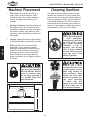
DXZ_`e\GcXZ\d\ek
=cffiCfX[1 This machine distributes a
heavy load in a small footprint. Some
residential floors may require additional
bracing to support both machine and
operator.
Nfib`e^:c\XiXeZ\j1 Consider existing and
anticipated needs, size of material to be
processed through the machine, and space
for auxiliary stands, work tables or other
machinery when establishing a location for
your shaper.
C`^_k`e^1 Lighting should be bright enough
to eliminate shadow and prevent eye strain.
<c\Zki`ZXc1Electrical circuits must be
dedicated or large enough to handle
amperage requirements. Outlets must be
located near each machine, so power or
extension cords are clear of high-traffic
areas. Follow local electrical codes for
proper installation of new lighting, outlets,
or circuits.
:c\Xe`e^DXZ_`e\
The table and other unpainted parts of your
machine are coated with a waxy grease that
protects them from corrosion during shipment.
Clean this grease off with a solvent cleaner or
citrus-based degreaser. DO NOT use chlorinebased solvents such as brake parts cleaner or
acetone—if you happen to splash some onto a
painted surface, you will ruin the finish.
E<M<IZc\Xen`k_^Xjfc`e\
fi fk_\i g\kifc\ld$
YXj\[jfcm\ekj%Dfjk_Xm\
cfn ]cXj_ gf`ekj# n_`Z_
dXb\ k_\d \oki\d\cp
]cXddXYc\% 8 i`jb f]
\ogcfj`fe Xe[ Ylie`e^
\o`jkj `] k_\j\ gif[lZkj
Xi\lj\[%J\i`fljg\ijfeXc
`ealip dXp fZZli `] k_`j
nXie`e^`j`^efi\[
8CN8PJ nfib `e n\cc$
m\ek`cXk\[Xi\Xj]Xi]ifd
gfjj`Yc\ `^e`k`fe jfliZ\j
n_\e lj`e^ jfcm\ekj kf
Zc\Xe dXZ_`e\ip% DXep
jfcm\ekj Xi\ kfo`Z n_\e
`e_Xc\[ fi `e^\jk\[% Lj\
ZXi\ n_\e [`jgfj`e^
f] nXjk\ iX^j Xe[
kfn\cj kf Y\ jli\ k_\p
;F EFK Zi\Xk\ ]`i\ fi
\em`ifed\ekXc_XqXi[j%
@EALIP?8Q8I;LekiX`e\[
lj\ijZXe`eali\k_\dj\cm\j
n`k_k_`jdXZ_`e\%I\jki`Zk
XZZ\jj kf dXZ_`e\ n_\e
pfl Xi\ XnXp# \jg\Z`Xccp `]
`k `j `ejkXcc\[ n_\i\ Z_`c$
[i\eXi\gi\j\ek%
34 3⁄4"
35 1⁄2"
=`^li\+% Working clearances.
-12-
Df[\cN(/).=fiDXZ_`e\jD]^%J`eZ\*&()
8jj\dYcp
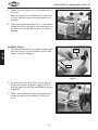
@ejkXcc`e^:lkk\i>lXi[
The guard tie-downs are used to secure the guard to the
table and are used when re-positioning the guard.
Cross
Bar
Kf`ejkXcck_\Zlkk\i^lXi[#[fk_\j\jk\gj1
(%
Insert each of the double-threaded bars into a guard
tie-down shaft, as shown in =`^li\,, and align the
groove in the bar with the set screw in the top of the
shaft.
Set
Screw
=`^li\,% Inserting cross bar into guard
tie-down shaft.
)%
J<KLG
Tighten the set screw to secure each cross bar, as
shown in =`^li\-.
=`^li\-% Securing cross bar in place.
*%
Thread the round knobs onto each end of the cross
bars, as shown in =`^li\..
=`^li\.% Installing the cross bar knobs.
-13-
Df[\cN(/).=fiDXZ_`e\jD]^%J`eZ\*&()
+%
Position the cutter guard over the threaded holes in
the table.
Efk\1K_\^lXi[ZXeY\gfj`k`fe\[fm\i\`k_\igX`i
f]_fc\j#[\g\e[`e^lgfek_\i\hl`i\d\ekjf]k_\
fg\iXk`fe%
,%
Insert the tie-down assemblies with 1⁄2" flat washers
through the slots in the guard, and thread them into
the table to secure the guard in place, as shown in
=`^li\/.
=`^li\/% Securing the guard to the table.
@ejkXcc`e^=\eZ\
J<KLG
(%
Slide a handwheel onto a fence adjuster shaft as you
align the set screw in the handwheel with the shaft
indent, as shown in =`^li\0.
Indent
Groove
=`^li\0% Attaching handwheel to fence
adjuster.
)%
On each side of the guard, insert a fence adjuster
through the bracket, as shown in =`^li\(', and
align the groove on the shaft (see =`^li\0) with the
middle bolt.
*%
Tighten the middle bolt into the shaft groove just
enough to keep the fence adjuster in place as it
turns.
=`^li\('% Installing fence adjuster.
-14-
Df[\cN(/).=fiDXZ_`e\jD]^%J`eZ\*&()
+%
For each side of the guard, thread the fence
adjuster into the fence brackets, as shown in
=`^li\((.
Fence Bracket
=`^li\((% Attaching fence bracket to
adjuster.
,%
Use the lock handles to secure the fence brackets to
the guard, as shown in =`^li\().
Lock Handle
J<KLG
=`^li\()% Fence bracket secured with
lock handle.
-%
Attach the fence boards to the fence brackets
with (6) 5⁄16"-18 x 1" Phillips head screws, 5⁄16"
flat washers, and 5⁄16"-18 hex nuts, as shown in
=`^li\(*.
Efk\1@]lj`e^pflifne]\eZ\YfXi[j#dXb\jli\k_\
Zflek\ijleb_fc\j`epfli]\eZ\dXk\i`XcXi\[\\g
\efl^_jfk_Xkk_\\ek`i\jZi\n_\X[`jY\cfnk_\
]\eZ\jli]XZ\%K_`jn`ccgi\m\ekk_\jZi\nj]ifd
`ek\i]\i`e^n`k_k_\nfibg`\Z\[li`e^fg\iXk`fej%
=`^li\(*% Attaching fence boards.
-15-
Df[\cN(/).=fiDXZ_`e\jD]^%J`eZ\*&()
8kkXZ_`e^JX]\kp>lXi[
(%
Place the safety guard over the threaded holes on
top of the guard body.
)%
Thread the (2) 5⁄16-18 x 4 " knob bolts with 5⁄16" flat
washers through the safety guard and into the guard
body to secure the cover, as shown in =`^li\(+.
Safety Guard
=`^li\(+% Installing safety guard.
@ejkXcc`e^Jg`e[c\?\`^_k?Xe[n_\\c?Xe[c\
J<KLG
Thread the handle into the handwheel, as shown in
=`^li\(,.
=`^li\(,% Handwheel handle installed.
@ejkXcc`e^M$9\ck
To install the V-belt (see =`^li\(-), follow the
instructions in the M$9\ckK\ej`fe`e^I\gcXZ\d\ek
procedureon GX^\*/.
V-Belt
=`^li\(-% V-belt installed.
-16-
Df[\cN(/).=fiDXZ_`e\jD]^%J`eZ\*&()
KXYc\@ej\ik8[aljkd\ek
The aluminum table insert is held in place by a cast
iron insert ring, which should be adjusted level with the
table top (see =`^li\(.). This is necessary to avoid the
workpiece catching on the insert or ring during operation,
causing an unsafe condition and poor cutting results.
KfdXb\k_\`ej\ikjXe[`ej\iki`e^c\m\cn`k_k_\kXYc\
kfg#[fk_\j\jk\gj1
DISCONNECT SHAPER FROM POWER!
)%
Remove the table inserts, then remove the three
Phillips screws that secure the insert ring to the
table top.
*%
Lay a precision straightedge across the insert ring
and the table, then adjust the three set screws that
are in the other holes (see =`^li\(.) until the insert
ring is level with the table top in all directions.
+%
Replace the Phillips screws, but do not overtighten
them.
,%
Replace the table inserts, then use the straightedge
to re-check the inserts. If necessary, repeat this
procedure until both the insert ring and table
inserts are completely level with the table top in all
directions.
=`^li\(.% Leveling the table insert ring.
;ljk:fcc\Zk`fe
I\Zfdd\e[\[:=DXk;ljkGfik1%%%%%%%%%%%%%%%% +'':=D
Do not confuse this CFM recommendation with the rating
of the dust collector. To determine the CFM at the
dust port, you must take into account many variables,
including the CFM rating of the dust collector, the length
of hose between the dust collector and the machine, the
amount of branches or Y's, and the amount of other open
lines throughout the system. Explaining this calculation
is beyond the scope of this manual. If you are unsure of
your system, consult an expert or purchase a good dust
collection "how-to" book.
Connect a 4" flexible dust collection hose to the rear of
the cutter guard, and use a hose clamp to secure it in
place. Tug on the hose to make sure that it is firmly held
in place.
-17-
;FEFKfg\iXk\k_\Df[\cN(/).n`k_$
flk Xe X[\hlXk\ [ljk Zfcc\Zk`fe jpj$
k\d% K_`j dXZ_`e\ Zi\Xk\j jlYjkXek`Xc
Xdflekjf]nff[[ljkn_`c\fg\iXk`e^%
=X`cli\kflj\X[ljkZfcc\Zk`fejpjk\d
ZXei\jlck`ej_fikXe[cfe^$k\idi\jg`$
iXkfip`cce\jj%
J<KLG
(%
Df[\cN(/).=fiDXZ_`e\jD]^%J`eZ\*&()
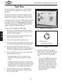
K\jkIle
Once the assembly is complete, test run your machine
to make sure it runs properly and is ready for regular
operation.
The test run consists of verifying the following: 1) The
motor powers up and runs correctly, and 2) the safety
feature on the emergency STOP button works correctly.
If, during the test run, you cannot easily locate the source
of an unusual noise or vibration, stop using the machine
immediately, then review KiflYc\j_ffk`e^ on GX^\+*.
If you still cannot remedy a problem, contact our Tech
Support at (360) 734-3482 for assistance.
Kfk\jkilek_\dXZ_`e\#[fk_\j\jk\gj1
J<KLG
(%
=`^li\(/% Control panel.
Make sure you understand the safety instructions
at the beginning of the manual, and verify that the
machine is setup properly.
)%
Ensure all tools and objects used during setup are
cleared away from the machine.
*%
Connect the machine to the power source.
+%
Push the ON button (see =`^li\(/) to enable power
to the motor—the power source lamp should light.
,%
Push the emergency STOP switch, then twist it
clockwise so it pops out. When the switch pops out it
is reset and ready for operation (see =`^li\(0).
KN@JK
KfI\j\kJn`kZ_%%%
-%
Turn the FWD/REV switch to the right to verify the
machine operates correctly.
— When operating correctly, the machine runs
smoothly with little or no vibration or rubbing
noises.
— Investigate and correct strange or unusual noises
or vibrations before operating the machine further.
Always disconnect the machine from power when
investigating or correcting potential problems.
.%
Turn the FWD/REV switch to the OFF (middle)
position and press the emergency STOP switch to
turn the machine F==.
-18-
Kn`jk9lkkfe:cfZbn`j\
=`^li\(0% Resetting the emergency stop
switch.
/%
WITHOUT resetting the emergency
STOP switch, turn the FWD/REV switch
to the right in an attempt to start the
machine. The machine should EFK
start.
— If the machine ;F<J start (with the
emergency STOP button pushed in),
immediately disconnect power to
the machine. The emergency STOP
switch safety feature is not working
correctly. This safety feature must
work properly before proceeding
with regular operations. Call Tech
Support for help.
Df[\cN(/).=fiDXZ_`e\jD]^%J`eZ\*&()
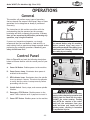
FG<I8K@FEJ
>\e\iXc
This machine will perform many types of operations
that are beyond the scope of this manual. Many of these
operations can be dangerous or deadly if performed
incorrectly.
The instructions in this section are written with the
understanding that the operator has the necessary
knowledge and skills to operate this machine. @]XkXep
k`d\pflXi\\og\i`\eZ`e^[`]]`Zlck`\jg\i]fid`e^Xep
fg\iXk`fe#jkfglj`e^k_\dXZ_`e\
If you are an inexperienced operator, we strongly
recommend that you read books or trade articles, or
seek training from an experienced shaper operator before
performing any unfamiliar operations. 8Yfm\Xcc#pfli
jX]\kpj_flc[Zfd\]`ijk
I<8;Xe[le[\ijkXe[k_`j\ek`i\`ejkilZ$
k`fe dXelXc Y\]fi\ lj`e^ k_`j dXZ_`e\%
J\i`flj g\ijfeXc `ealip dXp fZZli `]
jX]\kpXe[fg\iXk`feXc`e]fidXk`fe`jefk
le[\ijkff[ Xe[ ]fccfn\[% ;F EFK i`jb
pflijX]\kpYpefki\X[`e^
:fekifcGXe\c
B
C
A
8% Gfn\iFE9lkkfe%Enables power to the machine.
9% Gfn\iJfliZ\CXdg%Illuminates when power is
enabled to the machine.
:% I<M@e[`ZXkfiCXdg%Illuminates when the spindle
is set to rotate in reverse. This alerts the operator
to verify that the cutter is setup correctly before
proceeding with the cut.
E
D
F
=`^li\)'% Control panel.
;% Jg`e[c\Jn`kZ_%Starts, stops, and reverses spindle
rotation.
<% <d\i^\eZpJKFG9lkkfe%Disables power to the
motor. Twist clockwise until it pops out to reset it.
=% Gfn\iF==9lkkfe% Disables power to the machine.
-19-
8CN8PJZ_\Zbk_\[`i\Zk`fef]k_\Zlkk\i
ifkXk`feY\]fi\Y\^`ee`e^fg\iXk`feXe[
8CN8PJ]\\[k_\jkfZb`ekfk_\Zlkk\i
8>8@EJK k_\ Zlkk\i ifkXk`fe% =\\[`e^
jkfZb N@K? k_\ ifkXk`fe f] k_\ Zlkk\i
Zflc[ glcc k_\ nfibg`\Z\ ]ifd pfli
_Xe[j Xe[ [iXn pfli _Xe[j `ekf k_\
jg`ee`e^ Zlkk\i# i\jlck`e^ `e cXZ\iXk`fe
fiXdglkXk`fe`eali`\j%
FG<I8K@FEJ
Refer to =`^li\)' and read the following descriptions
below to become familiar with the control panel of your
shaper.
Df[\cN(/).=fiDXZ_`e\jD]^%J`eZ\*&()
:lkk\i?\`^_k
The cutter height is adjusted with the height handwheel.
To gauge the cutter height in relation to the table, use
the height scale or a precision ruler with fine graduations.
An alternative method would be to place a sample of the
shaped cut next to the cutter.
KfZ_Xe^\k_\Zlkk\i_\`^_k#[fk_\j\jk\gj1
DISCONNECT SHAPER FROM POWER!
)%
Loosen the spindle lock on the left side of the
cabinet (see =`^li\)().
*%
Rotate the spindle height handwheel to bring the
cutter to the required height, then re-tighten the
lock (see =`^li\))).
FG<I8K@FEJ
(%
=`^li\)(% Spindle lock on the left side of
the cabinet.
Height
Scale
Spindle Height
Handwheel
=`^li\))% Spindle height scale and
handwheel.
-20-
Df[\cN(/).=fiDXZ_`e\jD]^%J`eZ\*&()
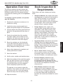
Fg\iXk`feFm\im`\n
This overview explains the basic process that
happens during an operation with this machine.
Familiarize yourself with this process to better
understand the remaining parts of the Fg\iXk`fe
section.
JkfZb@ejg\Zk`fe
I\hl`i\d\ekj
Follow these rules when choosing and cutting
stock:
Nfibg`\Z\DXk\i`Xc1 Your shaper and cutters
are designed to cut wood and wood products
ONLY! DO NOT attempt to cut man-made
materials (such as glass, metal, plastics,
etc.) that may cause the cutter or workpiece
to break apart, which could cause serious
personal injury or property damage.
=fi\`^eFYa\Zkj1 Nails, staples, dirt,
rocks and other foreign objects are often
embedded in wood. While cutting, these
objects can become dislodged and hit the
operator, cause kickback, and break or chip
the cutter, which might then fly apart.
Always visually inspect your workpiece for
these items. If they cannot be removed, do
NOT cut the workpiece.
CXi^\&Cffj\Befkj1 Loose knots can become
dislodged during the shaping operation.
Large knots can cause kickback and machine
damage. Choose workpieces that do not have
large/loose knots or plan ahead to avoid
cutting through them.
N\kfi>i\\eJkfZb1 Cutting wood
with a moisture content over 20% causes
unnecessary wear on the cutter, increases
the risk of kickback, and yields poor results.
<oZ\jj`m\NXig`e^1 Workpieces with
excessive cupping, bowing, or twisting
are dangerous to shape because they are
unstable and often unpredictable when being
cut. DO NOT use workpieces with these
characteristics!
D`efiNXig`e^1 Workpieces with slight
cupping can be safely supported if the
cupped side is facing the table or the fence.
On the contrary, a workpiece supported
on the bowed side could rock during the
operation and could cause kickback or severe
injury.
KfZfdgc\k\Xkpg`ZXcfg\iXk`fe#k_\fg\iXkfi
[f\jk_\]fccfn`e^1
(%
Examines the workpiece to make sure it is
suitable for cutting.
)%
Installs the cutter onto the spindle and
adjusts the spindle height for the operation.
*%
Correctly adjusts the safety guard and fence
boards for the operation and locks them in
place.
+%
Checks the outfeed side of the machine
for proper support and to make sure the
workpiece can safely move past the cutter
without interference from other objects.
,%
Places the workpiece on the infeed side
of the table and firmly against the fence,
stabilizing it with hold-downs, jigs, or other
safety workpiece holding devices.
-%
Wears safety glasses and a respirator, and
locates push sticks if needed.
.%
Starts the machine.
/%
Verifies cutter rotation and feed directions.
0%
Holds the workpiece firmly and flatly against
both the table and fence, and then pushes
the workpiece past the cutter at a steady
and controlled rate until the workpiece
moves completely beyond the cutter.
The operator is very careful to keep the
workpiece firmly against the table and fence
during the entire cut, while also keeping
hands well away from the spinning cutter.
('% Stops the machine.
-21-
FG<I8K@FEJ
Df[\cN(/).=fiDXZ_`e\jD]^%J`eZ\*&()
:_Xe^`e^Jg`e[c\Jg\\[j
The spindle speeds for the Model W1827 are 3600, 5100,
8000, and 10,000 RPM.
Cutting Edge
Moves Much
Faster
FG<I8K@FEJ
Lj\k_\]fccfn`e^ilc\jn_\ej\c\Zk`e^k_\jg\\[]fi
pflifg\iXk`fe1
•
Use scrap stock similar to your workpiece to find
the right spindle speed and feed rate so that the
resulting cut is smooth and requires little sanding to
finish.
•
Reduce spindle speed or increase feed rate if your
workpiece becomes glazed or burned.
•
Increase spindle speed or decrease feed rate if your
workpiece shows a rough or washboard surface.
•
The cutting edges of large cutters travel faster
than those of smaller cutters at the same spindle
speed (see =`^li\)*). Use slower speeds for larger
cutters.
Same Spindle Speed
=`^li\)*% Relative speed of cutting edges
between large and small cutters.
Spindle
10,000
8000
5100
3600
The spindle speed is changed by adjusting the V-belt
position on the motor and spindle pulleys, as illustrated in
=`^li\)+.
Kfi\gfj`k`fek_\M$Y\ckfek_\glcc\pj#[fk_\j\jk\gj1
Motor
(%
DISCONNECT SHAPER FROM POWER!
)%
Remove the side and rear motor access panels.
*%
Loosen the two motor adjustment hex bolts (see
=`^li\),), then slide the motor toward the spindle
assembly% DO NOT remove the bolts completely.
+%
Position the V-belt on the pulleys for the selected
speed.
,%
Slide the motor and motor mount assembly to the
left until the V-belt is snug, then tighten the bolts.
The amount of V-belt deflection between the pulleys
should be approximately 1⁄4" when pressed with
moderate pressure.
-%
Check to make sure the V-belt is correctly aligned on
both pulleys (refer to Glcc\p8c`^ed\ekon GX^\+'
for detailed instructions).
=`^li\)+% V-belt positions for the
different spindle speeds.
Loosen
These
Bolts
=`^li\),% Motor adjustment hex bolts.
-22-
Df[\cN(/).=fiDXZ_`e\jD]^%J`eZ\*&()
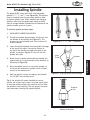
@ejkXcc`e^Jg`e[c\
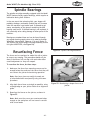
The Model W1827 comes with three interchangeable
spindles—1 1⁄4", 1", and 3⁄4" (see =`^li\)-). The spindles
must be inserted correctly and remain stable in order
to produce quality work. When installing and changing
spindles, make sure the spindle seats snugly and that
there is enough drawbar threaded into the bottom of the
spindle to safely secure it in place.
Kf`ejkXccXjg`e[c\#[fk_\j\jk\gj1
(%
DISCONNECT SHAPER FROM POWER!
)%
Thread the drawbar approximately 10-15 turns into
the bottom of the spindle (see =`^li\).). The
drawbar has two threaded ends. One of them will
remain exposed.
*%
Insert the spindle/drawbar into the spindle cartridge
at the top of the table. Line up the notches at
the top of the spindle cartridge with those in the
spindle, as shown in =`^li\).. You will feel the
spindle seat itself.
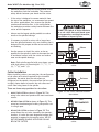
Reach into the cabinet and thread the drawbar nut,
tapered side up, onto the bottom of the drawbar, as
illustrated in =`^li\)/.
,%
Place the spindle wrench on top of the spindle, so
it fits over the head of the spindle. Place a 15mm
wrench on the drawbar nut.
-%
Hold the spindle in place and tighten the drawbar
nut. DO NOT use excessive force.
K`g1@]k_\jg`e[c\n`cci\dX`e`ejkXcc\[]fij\m\iXc
dfek_j#lj\XZc\XeiX^kfn`g\Xm\ipk_`eZfXkf]c`^_k
f`cfekfk_\dXk`e^jli]XZ\jkffdlZ_f`cn`ccefkXccfn
k_\jg`e[c\kfj\Xkgifg\icp %K_`jn`ccgi\m\ekZfiifj`fe
k_XkZflc[dXb\i\dfm`e^k_\jg`e[c\[`]]`Zlck%
Align
These
Drawbar
=`^li\).% Aligning spindle and cartridge.
Drawbar
Nut
=`^li\)/% Drawbar nut threaded onto
bottom of drawbar.
-23-
FG<I8K@FEJ
+%
=`^li\)-% 1 1⁄4", 1", and 3⁄4" spindles.
Df[\cN(/).=fiDXZ_`e\jD]^%J`eZ\*&()
However, some cutters are designed to shape from the
top of the workpiece, which exposes the operator to the
spinning cutter and increases the risk of operator injury.
To avoid this hazard, you can cut from the bottom of the
workpiece by mounting the cutter upside-down on the
spindle, reversing the spindle rotation, and feeding the
workpiece past the cutter from left to right. Refer to
the following :lkk\i@ejkXccXk`fe procedurefor detailed
instructions.
:lkk\i@ejkXccXk`fe
FG<I8K@FEJ
The Model W1827 accommodates cutters that have 3⁄4", 1",
and 1 1⁄4" center bores when used with the corresponding
spindle. A large variety of shaper cutters are available
through your local Woodstock International Inc. Dealer.
Kf\ejli\XjX]\Xe[\]]`Z`\ekfg\iXk`fe#]fccfnk_\j\
ilc\jn_\e`ejkXcc`e^Zlkk\ij1
•
The cutting edges of large cutters travel faster than
smaller ones at the same spindle speed. Cutters with
a 3 1⁄2" or larger outside diameter must be operated
at the slowest speed.
•
Do not use a spindle speed that exceeds the speed
rating of the cutter.
•
Wear heavy leather gloves when handling cutters to
avoid laceration injuries—cutters are SHARP!
•
Keep the spindle, spacers, and cutter clean and free
of debris to prevent them from binding when placed
on the spindle.
•
Use the smallest table insert opening possible to
keep the gap between the table surface and the
cutter to a minimum. This will help keep wood
chips from falling into the cabinet, provide better
workpiece support, and increase operator safety by
reducing risk of kickback or accidental contact with
the cutter.
-24-
un
terclockw
ise
Most cutters are designed to rotate counterclockwise
and cut the stock from underneath the workpiece, which
provides a safety barrier between the spinning cutter and
the operator. In this case, the workpiece is fed past the
cutter from right to left—against the cutter rotation (see
the illustration in =`^li\)0).
Co
:lkk\iIfkXk`fe;`i\Zk`fe
Direction Of Feed
=`^li\)0% Typical feeding operation with
cutter rotating counterclockwise.
Df[\cN(/).=fiDXZ_`e\jD]^%J`eZ\*&()
•
Whenever possible, setup the cutter so that it cuts
the workpiece from the underside. This creates a
safety barrier between your hands and the cutter.
•
If the cutter is designed to remove material from
the top of the workpiece, we recommend you mount
the cutter upside down, then reverse the spindle
rotation and feed direction. In this configuration,
the workpiece provides a safety barrier between the
cutter and the operator.
•
Always use the largest spindle possible to reduce
stress on the spindle bearings.
•
If necessary to install a cutter with a larger bore
than the spindle diameter, only use a bushing that is
designed for this purpose and do not use more than
one bushing.
•
;FEFKlj\XjgXZ\ififk_\ijlYjk`klk\
]fiXilYZfccXik_XkZflc[Yi\XbXgXik
[li`e^fg\iXk`fe#i\jlck`e^`ecXZ\iXk`fe#
XdglkXk`fefi`dgXZk`eali`\j%
6WdkZ
Use the spacers to install the cutter as low as
possible on the spindle in order to decrease the risk
of accidental contact with the cutter and reduce
wear on the spindle bearings.
Efk\1<XZ_jg`e[c\jlggc`\[n`k_pflij_Xg\iZfd\j
n`k_\`^_kjgXZ\ij`ek_\j\_\`^_kj1(Ð+# *Ð/# (Ð)
) # *Ð+) #Xe[() %
=`^li\*'%Rub collar mounted above
cutter.
Before installing cutters, you must plan the configuration
of rub collars and cutters required for the intended
application. No matter how the rub collars are
configured on the spindle, they must allow the hex nuts
to tightly fasten down to prevent the rub collars and
cutter from being loose on the spindle.
9\kn\\e
K_\i\Xi\k_i\\j\klggfj`k`fej]fiilYZfccXij1
89FM<K?<:LKK<I as shown in =`^li\*'% This
setup is the safest and produces the most consistent
results.
9<KN<<EKNF:LKK<IJ as shown in =`^li\*(% This
setup has the advantage of making two profile cuts
in a single pass.
9<CFNK?<:LKK<I as shown in =`^li\*)% This
setup allows the cut to be viewed by the operator;
however, it is also the most dangerous because the
operator is exposed to the moving cutter. WE DO
NOT RECOMMEND SHAPING WITH A RUB COLLAR
BELOW THE CUTTER!
-25-
=`^li\*(%Rub collar mounted between
two cutters.
EFK
I<:FDD<E;<;
9\cfn
=`^li\*)%Rub collar mounted below
cutter.
FG<I8K@FEJ
:lkk\i@ejkXccXk`fe
Df[\cN(/).=fiDXZ_`e\jD]^%J`eZ\*&()
Kf`ejkXccXZlkk\i#[fk_\j\jk\gj1
(%
DISCONNECT SHAPER FROM POWER!
FG<I8K@FEJ
Efk\1=fiZfem\e`\eZ\#i\dfm\k_\]\eZ\Xjj\dYcp
Y\]fi\g\i]fid`e^k_\]fccfn`e^jk\gj%
)%
Remove the two spindle nuts from the spindle.
*%
Place the required spindle spacers on the spindle to
raise the cutter to the proper distance.
+%
Protecting your hands from the sharp edges, slide
the cutter onto the spindle, making sure the cutting
edges are facing in the right direction for the
selected spindle rotation.
,%
Place the additional spacers onto the spindle as
necessary (see =`^li\**).
-%
Thread one spindle nut tightly onto the spindle to
secure the components, then thread the second
spindle nut against the first to act as a lock nut, as
shown in =`^li\**.
Always use a spindle lock nut during operation to
reduce the risk of the cutter or spindle components
leaving the spindle and flying at the operator.
-26-
Nuts
Spacers
Cutter
=`^li\**% Tightening the spindle nuts to
secure the spindle components.
Df[\cN(/).=fiDXZ_`e\jD]^%J`eZ\*&()
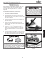
?fc[$;fnej
Each hold-down is independently adjustable, and, when
properly positioned, they firmly hold the workpiece
flat on the table and against the fence, as shown in
=`^li\*+.
KfXjj\dYc\k_\_fc[$[fnej#[fk_\j\jk\gj1
DISCONNECT SHAPER FROM POWER!
)%
Slide a hold-down into each of the cast iron holddown brackets with the large holes, and secure them
with the lock handles.
*%
Insert the bracket bars into the fence brackets and
hold-down bracket.
+%
Position the above assemblies according to the
workpiece size, then use the lock handles to secure
them in place.
,%
Insert the 5⁄16"–18 x 3/8" knob bolts with the 2 1⁄2"
shafts into two hold-down brackets with the small
holes and loosely thread the T-nuts onto the knob
bolts.
-%
Slide the assemblies from Jk\g, into the table miter
slot, position them according to the workpiece size,
then tighten the knob bolts to secure their position.
8cnXpj n\Xi jX]\kp ^cXjj\j fi X ]XZ\ j_`\c[ n_\e
fg\iXk`e^k_`jdXZ_`e\kfXmf`[\p\fi]XZ\`eali`\j
]ifd ]cp`e^ [\Yi`j% Nff[ [ljk dXp ZXlj\ j_fik Xe[
cfe^$k\id i\jg`iXkfip `cce\jj% Kf Xmf`[ k_`j _XqXi[#
XcnXpjn\XiXi\jg`iXkfi[li`e^fg\iXk`fe%
-27-
=`^li\*+% Example of workpiece held in
place by hold-downs.
=`^li\*,% Hold-downs assembled and
installed.
FG<I8K@FEJ
(%
@] k_\ nfibg`\Z\ j_flc[ i`j\ lg n_\e
`k`jX^X`ejkk_\Zlkk\i#b`ZbYXZbZflc[
fZZli%Kfi\[lZ\k_\Z_XeZ\f]b`ZbYXZb
Xe[ j\i`flj g\ijfeXc `ealip# XcnXpj
gifg\icpj\Zli\k_\nfibg`\Z\n`k_k_\
_fc[$[fne[\m`Z\j[li`e^fg\iXk`fe%
Df[\cN(/).=fiDXZ_`e\jD]^%J`eZ\*&()
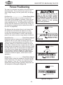
=\eZ\Gfj`k`fe`e^
The type of cut dictates the position of the fence pieces
during operation. There are three basic types of cuts
when straight shaping—full face, partial face, and plunge
cuts.
=lcc=XZ\:lk%%%%%%%%%%%%%%%%%%%%%%%%%%%%=\eZ\G`\Z\jF]]j\k
Full face cutting is similar to a jointer cut where the
entire edge of the workpiece is removed. These cuts are
most often performed with straight, tongue-and-groove,
crown moulding bits, etc. The outfeed fence must be set
forward from the infeed fence when full face cutting, so
the workpiece is supported by the outfeed fence after it
has been cut (=`^li\*-).
B\\g k_\ ]\eZ\ fg\e`e^ Xifle[ k_\
Zlkk\i Xj jdXcc Xj gfjj`Yc\ n`k_flk
`ek\i]\i`e^ n`k_ k_\ Zlkk\i ifkXk`fe%
K_`j Zfe]`^liXk`fe gifm`[\j k_\ Y\jk
jlggfik]fik_\nfibg`\Z\Xe[i\[lZ\j
fg\iXkfi \ogfjli\ kf k_\ jg`ee`e^
Zlkk\i[li`e^fg\iXk`fe%
<e[M`\n
FG<I8K@FEJ
The distance that the outfeed fence is set forward from
the infeed fence will dictate the depth of cut. Keep
in mind that removing too much material at one time
increases the risk of kickback. Instead, make multiple
passes if you need to remove a large amount of material.
GXik`Xc=XZ\:lk%%%%%%%%%%%%%%%%%%%%%% =\eZ\G`\Z\j8c`^e\[
Partial face cutting is where part of the edge of the
workpiece rides on a rub collar or bearing and is not cut.
These cuts are typically performed with profiles, stileand-rails, rabbets, etc. Partial face removal cuts can be
done with or without the fence, because the rub collar or
bearing dictates the depth of cut. When the fence is used
for these types of cuts, the fence pieces are aligned with
each other and are aligned with the forward most edge
of the bearing or router bit (=`^li\*.). (We strongly
recommend using the fence whenever possible because
it allows for maximum support, which results in safer
operation.)
Gcle^\:lkj%%%%%%%%%%%%%%%%%%%%%%%%%%%% =\eZ\G`\Z\j8c`^e\[
Plunge cutting is when the workpiece is fed over the top
of the cutter or bit. This type of cut is typically used for
slots, dovetails, T-slots, etc. The fence pieces must be
aligned when plunge cutting to provide a single plane for
the workpiece to slide against (=`^li\*/).
=`^li\*-% Full face cut.
<e[M`\n
=`^li\*.% Partial face cut.
<e[M`\n
;`i\Zk`fef]:lk
=`^li\*/% Plunge cut.
-28-
Df[\cN(/).=fiDXZ_`e\jD]^%J`eZ\*&()
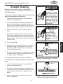
JkiX`^_kJ_Xg`e^
Because the shaper fence boards are independently
adjustable, you can set up the shaper to cut part or all of
the workpiece edge.
Kfj\klgk_\]\eZ\]fiZlkk`e^dXk\i`Xc]ifdk_\n_fc\
\[^\f]k_\nfibg`\Z\#[fk_\j\jk\gj1
(% Loosen the infeed fence bracket lock handle that
secures it to the guard body.
Turn the fence adjuster handwheel located on the
back of the fence bracket and adjust the infeed
fence until the workpiece contacts the cutter at the
desired location, then re-tighten the lock handles.
*%
Adjust the outfeed fence even with the infeed
fence.
+%
Set both fence boards as close to the cutter from
side-to-side as possible without interfering with the
cutter rotation. Make sure that the fence boards are
firmly secured to the brackets and that all knobs and
locks are tight.
,%
Turn the shaper FE.
-%
Using a piece of scrap wood, advance the workpiece
just past the edge of the outfeed fence, and turn
the machine F==. DO NOT remove the workpiece
from the infeed fence face.
.%
Once the cutter has come to a complete stop, adjust
the outfeed fence so that it just touches the newly
cut edge as shown in =`^li\*0%
/%
Tighten the outfeed fence bracket lock handle.
8DGLK8K@FE
?8Q8I;
8cnXpj]\\[k_\
nfibg`\Z\8>8@EJK
k_\[`i\Zk`fek_Xk
k_\Zlkk\i`jifkXk`e^
kfi\[lZ\k_\i`jbf]
`ealip%
<e[M`\n
=`^li\*0% Fence setup for jointing-type
operations (Guard Not Shown for Clarity).
Kfj\klgk_\]\eZ\]figXik`Xc\[^\i\dfmXc#[fk_\j\
jk\gj1
<e[M`\n
(%
Loosen the infeed fence bracket lock handle that
secures it to the guard body.
)%
Turn the fence adjuster handwheel and adjust the
infeed fence until the workpiece contacts the cutter
at the desired location, then re-tighten the lock
handle.
*% Align the outfeed fence with the infeed fence as
shown in =`^li\+'%
-29-
=`^li\+'%Fence setup for partial-edge
removal (Guard Removed for Clarity).
FG<I8K@FEJ
)%
8DGLK8K@FE
?8Q8I;
8ZZ`[\ekXc ZfekXZk
n`k_Xjg`ee`e^Zlkk\i
n`cc i\dfm\ gXikj f]
]`e^\ijficXi^\Z_lebj
f]]c\j_%JX]\kp^lXi[j
^i\Xkcpi\[lZ\k_`ji`jb
Xe[ dljk XcnXpj Y\
lj\[ n_\e fg\iXk`e^
k_`jdXZ_`e\
Df[\cN(/).=fiDXZ_`e\jD]^%J`eZ\*&()
,% Now place a straightedge against both faces of the
fence to check alignment.
:fii\Zk
N`k_>iX`e
IfkXk`fe
-% Once both fence pieces are aligned, tighten the
fence bracket lock handles.
.%
Set both fence boards as close to the cutter from
side-to-side as possible without interfering with the
cutter rotation. Make sure that the fence boards are
firmly secured to the brackets and that all knobs and
locks are tight.
Always feed the wood with the grain and against the
rotation of the cutter, as shown in =`^li\+(% Another
way to conceptualize this is to always feed the wood
into the cutter so that the cutter is pushing against the
direction of feed. Never feed wood in the same direction
as the cutter rotation. This is called a “climb cut” and is
extremely dangerous.
@e]\\[=\eZ\
Flk]\\[=\eZ\
=\\[;`i\Zk`fe
@eZfii\Zk
8^X`ejk>iX`e
IfkXk`fe
@e]\\[=\eZ\
Flk]\\[=\eZ\
=\\[;`i\Zk`fe
=`^li\+(% Feeding the workpiece with the
grain, against cutter rotation.
FG<I8K@FEJ
Also, examine the grain on the side edge of the board.
Whenever possible, run the board so the shaper cutters
are cutting with the grain as shown in =`^li\+(. This will
minimize the chance of tear out.
J_Xg`e^<e[>iX`e
It can be difficult to shape end grain and produce good
results. Consider the following points to help shape end
grain successfully.
•
Make sure the cutter is sharp. End grain is especially
tough and can easily burn.
•
Use the miter gauge when shaping end grain on a
narrow workpiece to ensure the workpiece remains
stable against the forces of the cutter.
•
•
Place a backing board behind the workpiece to
prevent tear out on the trailing edge.
Make end grain cuts before cuts that are with the
grain (see =`^li\+)). This will help prevent end
grain tear out.
-30-
1
4
3
2
Direction of Feed
=`^li\+)% Sequence for cutting the full
perimeter of a workpiece.
Df[\cN(/).=fiDXZ_`e\jD]^%J`eZ\*&()
=i\\_Xe[J_Xg`e^
Freehand shaping is shaping without using the fence.
A rub collar is used to control the depth of cut and
support the workpiece while cutting. A piece of wood is
clamped to the table to be used as a "starting block." The
block supports the workpiece while you slowly pivot the
workpiece into the cutter at the beginning of the cut (see
=`^li\+*). It is important to never start cutting at the
corner of workpiece or kickback may occur—even with the
support of a starting block.
=i\\_Xe[ j_Xg`e^ ZXe fecp Y\ [fe\
n_\eXilYZfccXi`jlj\[`ek_\Zlkk`e^
j\klg%N`k_flkXilYZfccXi#k_\i\`jef
nXp kf jlggfik k_\ nfibg`\Z\ [li`e^
k_\Zlk%
Kf j\k lg k_\ j_Xg\i ]fi ]i\\_Xe[ j_Xg`e^# [f k_\j\
jk\gj1
(%
G`mfk
Gf`ek
JkXik`e^
9cfZb
DISCONNECT SHAPER FROM POWER!
IfkXk`fe;`i\Zk`fe
)%
Remove the fence assembly from the shaper.
*%
Clamp the starting block to the table in a position
that allows you to feed the workpiece into and
against the rotation of the cutter (see =`^li\+*).
Jn`e^
IlY:fccXi
Nfibg`\Z\
=\\[;`i\Zk`fe
=`^li\+*% Feeding technique when using
a starting pin.
Install the cutter so it will cut in the correct
direction, and adjust the spindle height.
,%
Use a workpiece holding jig to guide the workpiece
and protect your hands (see the example in =`^li\
++). Read the tips on the next page when building a
workpiece holding jig.
-%
Place the workpiece/jig against the starting block.
.%
Slowly pivot and feed the workpiece into the cutter.
Avoid starting the cut on the corner of the workpiece
as kickback could occur. Once the cut is started, the
workpiece should be pulled away from the starting
block.
8DGLK8K@FE?8Q8I;
=i\\_Xe[ j_Xg`e^ `eZi\Xj\j k_\
i`jb f] `ealip Y\ZXlj\ k_\ Zlkk\i
`j dfi\ \ogfj\[ k_Xe ljlXc% Kf
i\[lZ\k_`ji`jb#8CN8PJ]\\[k_\
nfibg`\Z\ n`k_ X jkXik`e^ YcfZb
Xe[ X _fc[$[fne a`^ kf b\\g pfli
_Xe[j Xk X jX]\ [`jkXeZ\ ]ifd k_\
Zlkk\i[li`e^k_\\ek`i\fg\iXk`fe%
-31-
Workpiece
Holding Jig
Starting Block
=`^li\++% Example of using a holding jig
on a starting block.
FG<I8K@FEJ
+%
Df[\cN(/).=fiDXZ_`e\jD]^%J`eZ\*&()
FG<I8K@FEJ
N_\edXb`e^Xnfibg`\Z\_fc[`e^a`^#Zfej`[\ik_\
]fccfn`e^gf`ekj1
•
Secure your workpiece on the three sides that
will not be cut; use toggle clamps or fasten the
workpiece to the jig with wood screws.
•
Make the jig stable and sturdy. Fasten the hand holds
so hands will remain at least 6" away from the cutter
during the entire operation.
•
Ensure that clamps and hidden screws will not come
into contact with the cutter.
•
Design your fixture so that all cutting occurs
underneath the workpiece.
•
Make sure the workpiece rests flat on the table, not
on the fixture.
•
Remember, there is tremendous cutting force on
the workpiece. The workpiece holding jig must be
solid and stable, and the workpiece must be firmly
secured.
;\j`^e_fc[`e^a`^jjfjZi\njXe[ZcXdgj
;F EFK ZfekXZk k_\ Zlkk\i Xe[ k_\
nfibg`\Z\ `j _\c[ j\Zli\cp kf k_\ a`^%
K_\ a`^ dljk Y\ jkXYc\ fe k_\ j_Xg\i
kXYc\% =X`cli\ kf [f jf Zflc[ i\jlck `e
cXZ\iXk`fefiXdglkXk`fe`eali`\j%
K\dgcXk\j
A template is a workpiece holding jig with a shape or
pattern that rides against the rub collar during operation
as the cutter cuts the matching profile on the workpiece
edge (see =`^li\+,). Using templates allows identical
parts to be cut with speed and accuracy.
N_\edXb`e^Xk\dgcXk\j#Zfej`[\ik_\]fccfn`e^
gf`ekj1
•
Use a material that will smoothly follow the rub
collar or fence.
•
Always consider the cutting circle and rub collar
diameter for the correct depth of cut when designing
your pattern.
-32-
K\dgcXk\
IlY:fccXi
Nfibg`\Z\
=`^li\+,% Template setup against the rub
collar.
Df[\cN(/).=fiDXZ_`e\jD]^%J`eZ\*&()
Q\if:c\XiXeZ\=\eZ\
A shop-made zero-clearance fence (see =`^li\+-)
provides more support than a standard fence and reduces
tearout on narrow or fragile stock. Using a zero-clearance
fence is the best way to reduce the risk associated with
shaping inherently dangerous small stock.
Nff[jkfZb
*&+fik_`Zb\i
;i`ccknf$jk\g
Zflek\ijleb _fc\j
KfdXb\Xq\if$Zc\XiXeZ\]\eZ\#[fk_\j\jk\gj1
(%
DISCONNECT SHAPER FROM POWER!
)%
Remove the fasteners and fence boards on the split
fence.
*%
Place a 1x4 board over the fence brackets, and mark
and drill four holes for securing the board to the
brackets.
+%
Transpose an outline of the spindle, cutter, and
related components onto the board, leaving room for
the moving parts so they will not hit the board.
,%
Use a bandsaw, scroll saw, or jig saw to cut out the
outline.
-%
If necessary, cut out notches in the top of the board
for attaching the hold downs.
.%
Make sure the fence brackets are aligned, and
secure the board to the fence brackets with the
fasteners removed in Jk\g).
Efk\1=fiXkfkXccp]cXk]\eZ\]XZ\#gXjjk_\q\if$
Zc\XiXeZ\]\eZ\XZifjjXaf`ek\i#kXb`e^ZXi\efkkf
Zlk[\\g\efl^_k_Xkk_\Zlkk\i_`kjk_\dflek`e^
jZi\nj%I\]\ikfI\jli]XZ`e^=\eZ\feGX^\+(%
-33-
Dflekn`k_
\o`jk`e^_Xi[nXi\
=`^li\+-% Example of zero clearance
fence.
@e X[[`k`fe kf glj_ jk`Zbj# XcnXpj lj\
_fc[ [fnej fi ]\Xk_\iYfXi[j n_\e
j_Xg`e^ jdXcc fi eXiifn jkfZb% K_\j\
[\m`Z\j n`cc b\\g pfli _Xe[j XnXp
]ifdk_\jg`ee`e^Zlkk\i_\X[Xe[jlg$
gfik k_\ jkfZb jl]]`Z`\ekcp kf Xccfn X
jX]\ Xe[ \]]\Zk`m\ Zlk% =X`cli\ kf ]fc$
cfn k_`j nXie`e^ dXp c\X[ kf cXZ\iX$
k`fefiXdglkXk`fe`eali`\j%
FG<I8K@FEJ
Efk\1;i`cc`e^k_\_fc\j`jXknfjk\ggifZ\jj%;i`cc
k_\]`ijk_fc\jXcck_\nXpk_ifl^_k_\YfXi[n`k_
X[`Xd\k\iXc`kkc\cXi^\ik_Xek_\j_X]kf]k_\
dflek`e^jZi\n%;i`cck_\j\Zfe[_fc\j_Xc]nXp
k_ifl^_k_\YfXi[jn`k_X[`Xd\k\iXc`kkc\cXi^\i
k_Xek_\jZi\n_\X[%;i`cck_\j\j\Zfe[_fc\j[\\g
\efl^_k_Xkk_\jZi\n_\X[jn`ccY\n\ccY\cfnk_\
jli]XZ\f]k_\YfXi[%
:lkflkgif]`c\
f]Zlkk\iXiYfi
Df[\cN(/).=fiDXZ_`e\jD]^%J`eZ\*&()
9fo>lXi[
Shop-made box guards are an excellent way to enclose
the cutter to virtually eliminate accidental contact with
the cutter during operation. Having the cutter enclosed
also helps increase the efficiency of dust collection. The
drawback to box guards is that one size does not fit all.
Often, professional woodworkers who use box guards
make multiple guards that are different sizes.
=`^li\+. shows one way to make and attach a box guard
to the Model W1827. For durability and strength, use a
hardwood when making box guards. When installing the
box guard, adjust the box guard approximately 1⁄4" above
the stock you will shape and use hold downs on both
sides.
Efk\1 ;FEFKlj\k_\Yfo^lXi[XjX_fc[[fne2`ejk\X[#
lj\k_\gifm`[\[_fc[$[fnejfiX]\Xk_\iYfXi[k_Xk_Xj
k_\XY`c`kpkf]c\on`k_k_\d`efi_\`^_kmXi`Xk`fejf]pfli
jkfZb%
FG<I8K@FEJ
=\Xk_\i9fXi[j
Feather boards work similarly to the hold-downs provided
with the shaper in the way they hold stock tightly against
the fence and the table, while flexing with minor height
or width variations from stock as it passes through.
Because of the consistent pressure featherboards place on
the stock, cuts are more consistent, the risk of kickback
is greatly reduced, and the operator's hands do not need
to get near the cutter to maintain feeding pressure. If a
kickback does occur, featherboards will also slow down or
stop the workpiece.
1
2
3
=`^li\+.% Example demonstrating one
way to build a box guard.
*'$+,
+$-
A shop made featherboard can be made to accommodate
sizes of stock that the included hold-downs cannot reach.
=`^li\+/ shows the dimensions of a basic featherboard.
The ultimate size is flexible and should be built around
the size of stock you are shaping. The fingers can be cut
with a bandsaw or table saw.
To install a featherboard, feed a piece of stock halfway
through the machine, then turn the machine F==. Place
the featherboard against the stock so all the fingers touch
the edge of the stock, then clamp the featherboard to the
fence or table. For best results, place featherboards just
before and just after the cutter. An alternative mounting
method for tables is to rout a slot in the featherboard and
use T-slot mounting hardware to secure the featherboard.
-34-
:lk]`e^\ij
& $(&+k_`Zb
( /
(,$(/
&
Nff[
jkfZb
* +
;i`ccfiiflk
fgk`feXc_fc\
]fiK$jcfkdflek`e^
+$-
=`^li\+/% Basic featherboard
construction.
Df[\cN(/).=fiDXZ_`e\jD]^%J`eZ\*&()
8::<JJFI@<J
J_Xg\i8ZZ\jjfi`\j
The following shaper accessories may be available through your local Woodstock International Inc.
Dealer. If you do not have a dealer in your area, these products are also available through online
dealers. Please call or e-mail Woodstock International Inc. Customer Service to get a current listing of
dealers at: 1-800-840-8420 or at [email protected].
The N((', Nff[jkfZb9fXi[9l[[`\j hold the workpiece against
the table and fence during cutting operations. These Board Buddies®
are made from die-cast aluminum and feature non-marring green
neoprene rubber wheels. Because the wheels turn in both directions,
they function as hold-downs rather than anti-kickback devices. Mounts
to fences 3" to 3 1⁄2" high x 1" or wider with the optional Df[\cN(('.
12" Tracks, or the Df[\cN(('/ 24" Tracks.
The features of the Df[\cN(.-+JdXccGfn\i=\\[\iinclude: 1⁄8 HP,
110V, 1.2A motor; variable number of speeds between 6 1⁄2–39 FPM;
three synthetic rubber wheels (1 1⁄8"W x 3"D); forward and reverse
feed; X, Y, and Z adjustments; 13" vertical movement; and 11" horizontal movement.
The ;)',.8J?FG=FO8[aljkXYc\DfY`c\9Xj\ supports your shaper
so you can move it easily and lock it in position. Designed for long
term and frequent moving of heavy machinery.
-35-
FG<I8K@FEJ
The N(,''J?FG=FOI`^_k8e^c\A`^ allows you to make cuts
on board ends, and various other cuts with complete accuracy and
improved safety. Constructed using top quality aluminum castings and
plates which are machined to exacting tolerances. It has the perfect
weight-use ratio to dampen vibration, yet is still light enough to
easily slide the workpiece through the shaping process. Its quality and
precision are evident from the first cut.
Df[\cN(/).=fiDXZ_`e\jD]^%J`eZ\*&()
D8@EK<E8E:<
>\e\iXc
For optimum performance from your machine, follow
this maintenance schedule and refer to any specific
instructions given in this section.
Efk\1 K_`jdX`ek\eXeZ\jZ_\[lc\`jYXj\[feXm\iX^\
[X`cpljX^\%8[aljkk_\dX`ek\eXeZ\jZ_\[lc\kfdXkZ_
pfliljX^\`efi[\ikfb\\gpflij_Xg\iilee`e^jdffk_cp
Xe[gifk\Zkpfli`em\jkd\ek%
;X`cp1
• Clean and protect the top surfaces.
• Check/tighten loose mounting bolts.
• Check/replace damaged or dull cutters.
• Check/repair worn or damaged wires.
• Check/resolve any other unsafe condition.
D8B< JLI< k_Xk pfli dXZ_`e\ `j
legcl^^\[ [li`e^ Xcc dX`ek\eXeZ\ gif$
Z\[li\j@]k_`jnXie`e^`j`^efi\[#j\i`$
fljg\ijfeXc`ealipdXpfZZli%
N\\bcp1
• Clean the inside of the cabinet.
• Check the V-belt condition and tension (GX^\*/).
Dfek_cp1
• Lubricate the spindle slide and elevation leadscrew
(GX^\*.).
D8@EK<E8E:<
KXYc\9Xj\
Cleaning the Model W1763 is relatively easy. Vacuum
excess wood chips and sawdust, and wipe off the
remaining dust with a dry cloth. If any resin has built up,
use a resin dissolving cleaner to remove it.
Protect the unpainted cast iron surfaces on the table
by wiping the table clean after every use—this ensures
moisture from wood dust does not remain on bare metal
surfaces.
Keep the table rust-free with regular applications of a
quality paste wax or metal protectant.
-36-
Df[\cN(/).=fiDXZ_`e\jD]^%J`eZ\*&()
ClYi`ZXk`fe
Since all bearings are sealed and permanently lubricated,
simply leave them alone until they need to be replaced.
Do not lubricate them. However, the spindle slide and
leadscrew do need lubrication with NLGI#2 grease.
Leadscrew
KfclYi`ZXk\k_\jg`e[c\jc`[\Xe[c\X[jZi\n#[fk_\j\
jk\gj1
(%
DISCONNECT SHAPER FROM POWER!
)%
Use the spindle height handwheel to lower the
spindle all the way, then access the elevation
assembly through the rear of the cabinet (see
=`^li\+0).
*%
Use mineral spirits, shop rags, and a stiff brush
to clean away grease and built-up grime from
the surfaces of both slides and the threads of the
leadscrew, then apply a thin coat of NLGI#2 grease
or equivalent to these surfaces.
+%
Fully raise and lower the spindle to distribute the
grease.
Slide
=`^li\+0% Spindle slide and leadscrew.
D8@EK<E8E:<
-37-
Df[\cN(/).=fiDXZ_`e\jD]^%J`eZ\*&()
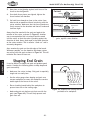
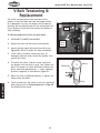
M$9\ckK\ej`fe`e^
I\gcXZ\d\ek
The V-belt transfers power from the motor to the
spindle. If the V-belt does not have the proper tension
or is damaged in any way, the shaper will not operate
optimally and unnecessary wear on the moving parts will
occur. Regularly check the V-belt tension and replace it
when necessary.
V-Belt
Kfk\ej`fe&i\gcXZ\k_\M$Y\ck#[fk_\j\jk\gj1
(%
DISCONNECT SHAPER FROM POWER!
)%
Remove the rear and side motor access panels.
Loosen
These
Bolts
D8@EK<E8E:<
*% Loosen the two motor adjustment hex bolts (see
=`^li\,')% DO NOT remove the bolts completely.
*%
If the V-belt is cracked, excessively worn, or
damaged, slide the motor toward the spindle, then
replace the V-belt.
+%
To tension the V-belt, slide the motor away from
the spindle until the V-belt is snug, then tighten the
bolts. The amount of V-belt deflection between the
pulley should be approximately 1⁄4" when moderate
pressure is applied, as illustrated in =`^li\,(.
,%
When the V-belt is adjusted properly, re-tighten the
motor mount hex bolts.
-%
Check to make sure the V-belt is correctly aligned on
both pulleys (refer to Glcc\p8c`^ed\ekon GX^\+'
for detailed instructions).
-38-
=`^li\,'% Motor adjustment hex bolts.
;\]c\Zk`fe
Glcc\p
Glcc\p
=`^li\,(% Checking V-belt tension.
Df[\cN(/).=fiDXZ_`e\jD]^%J`eZ\*&()
J<IM@:<
>\e\iXc
This section covers the most common service adjustments
or procedures that may need to be made during the life
of your machine.
If you require additional machine service not included
in this section, please contact Woodstock International
Technical Support at (360) 734-3482 or send e-mail to:
k\Z_$jlggfik7j_fg]fo%Y`q.
=\eZ\9fXi[8c`^ed\ek
For safe and accurate shaping, the fence boards must be
parallel with one another so that they properly support
the workpiece through the entire cutting operation.
D8B< JLI< k_Xk pfli dXZ_`e\ `j
legcl^^\[ [li`e^ Xcc dX`ek\eXeZ\ gif$
Z\[li\j@]k_`jnXie`e^`j`^efi\[#j\i`$
fljg\ijfeXc`ealipdXpfZZli%
KfZ_\ZbXe[Xc`^ek_\]\eZ\YfXi[jgXiXcc\cn`k_\XZ_
fk_\i#[fk_\j\jk\gj1
(%
DISCONNECT SHAPER FROM POWER!
)%
Make sure the fence boards are even with each
other, then place the straightedge against both fence
boards, as shown in =`^li\,).
— If there is a gap between the straightedge and the
fence boards, use shims as needed between the
fence boards and the mounting brackets to make
the boards completely parallel with each other
along their entire length.
=`^li\,)% Aligning fence boards.
J<IM@:<
-39-
Df[\cN(/).=fiDXZ_`e\jD]^%J`eZ\*&()
Glcc\p8c`^ed\ek
Pulley alignment is important to the performance of your
shaper. If the pulleys are just slightly out of alignment,
the shaper may suffer from power loss and decreased
V-belt life.
KfXc`^ek_\glcc\pj#[fk_\j\jk\gj1
(%
DISCONNECT SHAPER FROM POWER!
)%
Remove the motor cover from the back of the shaper
cabinet to expose the motor and pulleys.
*%
Check the alignment with a straightedge. If the
pulleys are in alignment, the straightedge should
touch the two sides of each pulley evenly, as shown
in =`^li\,*.
Set Screw
— If the pulleys are correctly aligned with each
other, no adjustments are needed. Replace the
motor cover.
— If the pulleys are NOT correctly aligned, proceed
with Jk\g+.
J<IM@:<
+%
This process is easiest with the help of another
person. Loosen the four bolts that attach the motor
to the motor base. One person should adjust the
motor either up or down while the other person
measures the alignment of the pulleys with a
straightedge.
,%
When the pulley alignment is correct, re-tighten the
motor to the motor base.
-%
Inspect your results. If necessary, repeat this
procedure until the pulleys are properly aligned.
Efk\1You can also make small adjustments in the
motor pulley alignment by raising or lowering it
along the motor shaft. To do this, loosen the two
set screws (one is shown in =`^li\,*) which are in
the groove of the middle motor pulley and move the
pulley into position. Tighten the set screws when the
alignment is satisfactory.
-40-
=`^li\,*% Checking pulley alignment.
Df[\cN(/).=fiDXZ_`e\jD]^%J`eZ\*&()
Jg`e[c\9\Xi`e^j
The spindle cartridge assembly equipped with the Model
W1827 features factory-sealed bearings, which require no
lubrication during their lifetime.
In the rare event that a bearing fails, your shaper will
probably develop a noticeable rumble that will increase
when the machine is put under load. If allowed to get
worse, overheating of the journal containing the bad
bearing could occur. If the bad bearing is not replaced, it
will eventually seize—doing damage to other parts of the
machine.
Bearings are standard sizes and can be found through
any regular bearing supply store or by ordering through
Woodstock International. However, it is much easier to
just replace the entire spindle cartridge assembly as one
unit (part #X1827157A, see =`^li\,+).
=`^li\,+% Spindle cartridge assembly.
I\jli]XZ`e^=\eZ\
The fence can be resurfaced or made flat with a jointer
to correct any warping. This procedure should only be
done if the fences will not align with each other after
careful adjustment or they are warped.
Kfi\jli]XZ\k_\]\eZ\#[fk_\j\jk\gj1
(%
Make sure the fence face mounting screws are far
enough below the surface of the fence that they will
not contact the jointer knives during operation.
Efk\1 E\n]\eZ\]XZ\jZXe\Xj`cpY\dX[\flk
f]X_Xi[nff[Xe[i\jli]XZ\[Yplj`e^k_`jjXd\
gifZ\[li\%
Align both fence faces as straight as possible, using
a straightedge or your jointer table as an alignment
guide.
*%
Resurface the fences on the jointer, as shown in
=`^li\,,.
Efk\1 DXb\jli\k_\jZi\njXi\Zflek\ijleb[\\g
\efl^_jfk_\nfibg`\Z\n`ccefkZfd\`eZfekXZk
n`k_jZi\n_\X[j%
-41-
=`^li\,,% Resurfacing a shaper fence on a
jointer.
J<IM@:<
)%
Df[\cN(/).=fiDXZ_`e\jD]^%J`eZ\*&()
To reduce the risk of kickbacks and to increase the
quality of cuts, it is important that the table and spindle
are perpendicular to each other in all directions. Use
a machinist's square or other precision square when
checking/adjusting these components to ensure accurate
results (see =`^li\j,-,.).
DXZ_`e`jk
JhlXi\
KfdXb\k_\kXYc\Xe[jg`e[c\g\ig\e[`ZlcXi#[fk_\j\
jk\gj1
(%
DISCONNECT SHAPER POWER!
)%
Remove the guard and fence assembly.
*%
Raise the spindle all the way up.
+%
Remove the locking fasteners, spacers, and cutters
from the spindle.
,%
Position a machinist square flat on the table and
up against the spindle (see =`^li\,-) and in
all directions (see =`^li\,.)—the spindle and
table should be perpendicular to each other in all
directions.
Jg`e[c\
Jg`e[c\$kf$KXYc\JhlXi`e^
0'
=ifekf]KXYc\
=`^li\,-% Illustration of using a machinist
square with the table and spindle.
— If spindle and table are not perpendicular to each
other in all directions, do these steps:
X% Loosen the four table adjustment bolts (see
=`^li\,/) enough so that the table can be
adjusted.
Jg`e[c\
DXZ_`e`jk
JhlXi\
=`^li\,.% Illustration of machinist square
at different directions around the spindle.
Y% Use a dead blow hammer to tap the table into
proper alignment with the spindle.
Z%
Re-tighten the four table adjustment bolts.
[% Repeat this Jk\guntil the spindle and
table are perpendicular to each other in all
directions.
J<IM@:<
Table Adjustment
Bolt (1 of 4)
=`^li\,/% Table adjusting bolt
(1 of 4).
-42-
Df[\cN(/).=fiDXZ_`e\jD]^%J`eZ\*&()
KiflYc\j_ffk`e^
This section covers the most common problems and corrections with this type of
machine. N8IE@E>;FEFKdXb\XepX[aljkd\ekjlek`cgfn\i`j[`jZfee\Zk\[Xe[
dfm`e^gXikj_Xm\Zfd\kfXZfdgc\k\jkfg
GIF9C<D
GFJJ@9C<:8LJ<
:FII<:K@M<8:K@FE
Machine does not start or a 1. Emergency STOP button pushed in. 1. Twist the STOP button clockwise until it pops out to
breaker trips.
reset it.
2. Power supply switched OFF or at 2. Ensure power supply is ON/has correct voltage.
fault.
3. Plug/receptacle at fault/wired 3. Test for good contacts; correct the wiring.
wrong.
4. Correct motor wiring connections (Page 46).
4. Motor connection wired wrong.
5. Thermal overload relay has 5. Reset; adjust trip load dial if necessary; replace.
tripped.
6. Ensure circuit size is correct/replace weak breaker.
6. Wall circuit breaker tripped.
7. Check/fix broken, disconnected, or corroded wires.
7. Wiring open/has high resistance.
8. Test/replace if faulty.
8. Start capacitor at fault.
9. Spindle switch/ON button at fault. 9. Replace.
10. Test/repair/replace.
10. Motor at fault.
Machine stalls or seems 1. Workpiece material not suitable for 1. Only cut wood/ensure moisture is below 20%.
underpowered.
machine.
2. Use correct, sharp cutter; reduce feed rate/depth
2. Machine undersized for task.
of cut.
3. Tension/replace V-belt (Page 38).
3. V-belt slipping.
4. Wire motor correctly (Page 46).
4. Motor wired incorrectly.
5. Replace loose pulley/shaft.
5. Pulley slipping on shaft.
6. Test/repair/replace.
6. Motor bearings at fault.
7. Clean motor, let cool, and reduce workload.
7. Motor overheated.
8. Spindle switch/ON button at fault. 8. Replace.
9. Test/repair/replace.
9. Motor at fault.
Machine has vibration or 1. Motor or component loose or bronoisy operation.
ken.
2. Cutter at fault.
3. V-belt worn or loose.
4. Motor fan rubbing on fan cover.
5. Spindle at fault.
6. Pulley loose.
7. Machine incorrectly installed.
8. Motor bearings at fault.
J<IM@:<
-43-
1. Inspect/replace damaged bolts/nuts, and re-tighten.
2. Replace damaged cutter.
3. Tension/replace V-belt (Page 38).
4. Fix/replace fan cover; replace loose/damaged fan.
5. Tighten loose spindle; replace defective spindle or
spindle cartridge.
6. Realign/replace shaft, pulley, set screw, and key.
7. Tighten mounting bolts; relocate/shim machine.
8. Test by rotating shaft; rotational grinding/loose
shaft requires bearing replacement.
Df[\cN(/).=fiDXZ_`e\jD]^%J`eZ\*&()
GIF9C<D
GFJJ@9C<:8LJ<
:FII<:K@M<8:K@FE
Spindle does not raise or
lower easily.
1. Spindle slide or elevation leadscrew 1. Clean the spindle slide and leadscrew, then
clogged with sawdust.
lubricate them (GX^\*.).
Workpiece
cut.
1.
Dull cutter.
2.
Too slow of a feed rate.
3.
Pitch build-up on cutter.
Cutter rotating in the wrong direc- 4.
tion (climb cutting).
5.
5. Taking too deep of a cut.
Fuzzy grain.
Chipping.
burns
when 1.
2.
3.
4.
1. Improper dust collection allowing
dust/chips to build up and interfere with cutting operation.
2. Wood may have high moisture content or surface wetness.
3. Dull cutter.
4. Inherent characteristic of wood
type.
Replace cutter or have it professionally sharpened.
Increase feed speed.
Clean cutter with a blade and bit cleaning solution.
Reverse the direction of the cutter rotation so it cuts
against direction of feed.
Make several passes of light cuts rather than one
heavy cut
1. Use correct dust collection system that is adequate
to efficiently remove dust/chips during operation.
2. Check moisture content and allow to dry if moisture
is more than 20%.
3. Replace or have cutter professionally sharpened.
4. Use a different wood type or plan for a sanding
operation.
1. Knots or conflicting grain direction 1. Inspect workpiece for knots and grain direction; only
use clean stock.
in wood.
2. Replace the cutter, or have it professionally sharp2. Nicked or chipped cutter.
ened.
3. Slow down the feed rate.
3. Feeding workpiece too fast.
4. Take a smaller depth of cut. (Always reduce cutting
4. Taking too deep of a cut.
depth when working with hard woods.)
5. Cutting against the grain of the 5. Cut with the grain of the wood.
wood.
J<IM@:<
1. Move smoothly or use a power feeder.
Divots in the edge of the 1. Inconsistent feed speed.
cut (snipe).
2. Inconsistent pressure against the 2. Apply constant pressure.
fence and rub collar.
3. Adjust fence.
3. Fence not adjusted correctly.
4. Use jointer/table saw to square up workpiece
4. Workpiece edge is warped.
edge.
5. Some amount of snipe may be 5. Plan ahead by shaping workpiece and cutting off
ends to remove snipe.
inevitable.
-44-
Df[\cN(/).=fiDXZ_`e\jD]^%J`eZ\*&()
<c\Zki`ZXcJX]\kp@ejkilZk`fej
These pages are current at the time of printing. However, in the spirit of improvement, we may
make changes to the electrical systems of future machines. Study this diagram carefully. If you notice
differences between your machine and these wiring diagrams, call Woodstock International Technical
Support at (360) 734-3482.
J?F:B?8Q8I;% Working on wiring that is
connected to a power source is extremely
dangerous. Touching electrified parts will
result in personal injury including but not
limited to severe burns, electrocution,
or death. Disconnect the power from
the machine before servicing electrical
components!
DFKFIN@I@E>% The motor wiring shown in
these diagrams is current at the time of
printing, but it may not match your machine.
Always use the wiring diagram inside the
motor junction box.
DF;@=@:8K@FEJ% Using aftermarket parts or
modifying the wiring beyond what is shown
in the diagram may lead to unpredictable
results, including serious injury or fire.
HL8C@=@<;<C<:KI@:@8E% Due to the inherent
hazards of electricity, only a qualified
electrician should perform wiring tasks on
this machine. If you are not a qualified
electrician, get help from one before
attempting any kind of wiring job.
:8G8:@KFIJ&@EM<IK<IJ% Some capacitors
and power inverters store an electrical
charge for up to five minutes after being
disconnected from the power source. To
avoid being shocked, wait at least this long
before working on these components.
N@I<:FEE<:K@FEJ% All connections must be
tight to prevent wires from loosening during
machine operation. Double-check all wires
disconnected or connected during any wiring
task to ensure tight connections.
<C<:KI@:8CI<HL@I<D<EKJ% You MUST follow
the electrical requirements at the beginning
of this manual when connecting your
machine to a power source.
N@I<&:FDGFE<EK;8D8><% Damaged wires
or components increase the risk of serious
personal injury, fire, or machine damage.
If you notice that any wires or components
are damaged while performing a wiring task,
replace those wires or components before
completing the task.
<OG<I@<E:@E>;@==@:LCK@<J% If you are
experiencing difficulties understanding the
information included in this section, contact
our Technical Support at (360) 734-3482.
WIRING DIAGRAM COLOR KEY
BLUE
WHITE
BROWN
GREEN
GRAY
YELLOW
YELLOW
GREEN
PURPLE
RED
ORANGE
PINK
-45-
LIGHT
BLUE
BLUE
WHITE
TURQUOISE
J<IM@:<
The photos and diagrams
included in this section are
best viewed in color. You
can view these pages in
color at www.shopfox.biz.
BLACK
Df[\cN(/).=fiDXZ_`e\jD]^%J`eZ\*&()
N`i`e^;`X^iXd
Control Panel
REV
Indicator Lamp
Power Source Lamp
T
5
U
V
6
V
S
T1
M5
3/L2
5/L3
2/T1
13NO
R
4/T2
6/T3
Emergency
STOP Button
R1
R
NO
1/L1
Contactor
U
KEDU
ZH-HC-3
4
A2
NHD C18-D
Spindle
Switch
T
A1
14NO
3
R
2
1 NC
1
4
1
3
M5
5
AMP
U/2
1
2
3
RESET
U
2
A2
V
V/4
24
36
4
NC
1
W/6
30
OFF Button
R R
5
ON Button
V
2
95
2
U
M5
OL Relay
NHD TH-20
V
T1
98
96
R
3
T
R1
Start Capacitor
400MFD 125VAC
)
1
(
6
R
'
Ground
V
J<IM@:<
T
2
M5
Junction
Box
U
&
Hot
Run Capacitor
50MFD 350VAC
220VAC
L6-30 Plug
(As Recommended)
Read
Page 45
220V Motor
JKFG
Before
Wiring
-46-
O
>
Ground
P
Hot
Df[\cN(/).=fiDXZ_`e\jD]^%J`eZ\*&()
G8IKJ
:XY`e\k
103
104
101
129
102
105
113
114
125
124
106
108 109 110
111
110
115
110
109
116
112
133
117
127
130
128
113
131
126
123
132
113
121
120 119
118
120
122
G8IKJ
-47-
Df[\cN(/).=fiDXZ_`e\jD]^%J`eZ\*&()
:XY`e\kGXikjC`jk
PART #
DESCRIPTION
REF
PART #
DESCRIPTION
XPSS08
X1827102
X1827103
X1827104
X1827105
X1827106
XPN08
XPLW04
XPW02
X1827111
XPN07
XPS12
X1827114
XPB24
XPB21
X1827117
SET SCREW 5/16-18 X 1/2
TABLE
TABLE INSERT 3" O.D.
TABLE INSERT 3-1/2" O.D.
CAST IRON INSERT RING
CABINET
HEX NUT 3/8-16
LOCK WASHER 3/8
FLAT WASHER 3/8
RIGHT TABLE BRACE
HEX NUT 10-24
PHLP HD SCR 1/4-20 X 5/8
REAR CABINET ACCESS PANEL
HEX BOLT 3/8-16 X 1-1/4
HEX BOLT 3/8-16 X 3/4
SIDE CABINET ACCESS PANEL
118
119
120
121
122
123
124
125
126
127
128
129
130
131
132
133
XPS08
X1827119
X1827120
X1827121
X1827122
X1827123
X1827124
X1827125
X1827126
X1827127
X1827128
XPFH21
X1827130
X1827131
X1827132
X1827133
PHLP HD SCR 10-24 X 3/4
TERMINAL BOX ASSEMBLY
STRAIN RELIEF 3/8" STRAIGHT
CONTACTOR NHD C-18D 220V
OL RELAY NHD TH-20 24-36A
CONTROL PANEL PLATE
LEFT TABLE BRACE
MITER GAUGE ASSEMBLY
SPINDLE SWITCH KEDU ZH-HC-3
POWER LAMP
REVERSE LAMP
FLAT HD SCR 10-24 X 3/4
ON BUTTON LA68-CT.AK10
OFF BUTTON LA68-CT.BK01
E-STOP BUTTON LA68-CT.BK01
CONTROL PANEL ASSEMBLY
G8IKJ
REF
101
102
103
104
105
106
108
109
110
111
112
113
114
115
116
117
-48-
151
150
157A
156
184
G8IKJ
-49152
153
154
155
157
156
158
156
163
164
159
161
162
160
165
181
182
183
178
179
180
175
176
177
172
173
174
170
171
167
168
169
166
Df[\cN(/).=fiDXZ_`e\jD]^%J`eZ\*&()
Jg`e[c\
Df[\cN(/).=fiDXZ_`e\jD]^%J`eZ\*&()
Jg`e[c\GXikjC`jk
PART #
DESCRIPTION
REF
PART #
DESCRIPTION
150
151
152
153
154
155
156
157
157A
158
159
160
161
162
163
164
165
166
X1827150
X1827151
X1827152
X1827153
X1827154
XPR68M
XP6008ZZ
X1827157
X1827157A
X1827158
X1827159
XPK55M
X1827161
X1827162
XPCAP17M
XPR43M
XPN37
XPN36
DRAWBAR 3/8-11
TAPER LOCK NUT 3/8-11
SPANNER NUT 30-3.5
SPANNER LOCK WASHER 30MM
SPINDLE PULLEY ASSEMBLY
EXT RETAINING RING 40MM
BALL BEARING 6008ZZ
QUILL
SPINDLE PULLEY & QUILL ASSY
BEARING SPACER
CARTRIDGE LOWER FLANGE
KEY 7 X 7 X 40
SPINDLE CARTRIDGE
CARTRIDGE UPPER FLANGE
CAP SCREW M4-.7 X 10
EXT RETAINING RING 50MM
HEX NUT 1-1/4-7 LH
HEX NUT 1-1/4-7
167
168
169
170
171
172
173
174
175
176
177
178
179
180
181
182
183
184
X1827167
X1827168
X1827169
X1827170
X1827171
X1827172
X1827173
X1827174
X1827175
X1827176
X1827177
X1827178
X1827179
X1827180
X1827181
X1827182
X1827183
X1827184
SPINDLE SPACER 1-1/4" X 1/4"
SPINDLE SPACER 1" X 1/4"
SPINDLE SPACER 3/4" X 1/4"
SPINDLE SPACER 1-1/4" X 3/8"
SPINDLE SPACER 1" X 3/8"
SPINDLE SPACER 1-1/4" X 1/2" 2-PC
SPINDLE SPACER 1" X 1/2" 2-PC
SPINDLE SPACER 3/4" X 1/2" 2-PC
SPINDLE SPACER 1-1/4" X 3/4" 2-PC
SPINDLE SPACER 1" X 3/4" 2-PC
SPINDLE SPACER 3/4" X 3/4" 2-PC
SPINDLE SPACER 1-1/4" X 1" 2-PC
SPINDLE SPACER 1" X 1" 2-PC
SPINDLE SPACER 3/4" X 1" 2-PC
SPINDLE 1-1/4"
SPINDLE 1"
SPINDLE 3/4"
BEARING SPACER
G8IKJ
REF
-50-
Df[\cN(/).=fiDXZ_`e\jD]^%J`eZ\*&()
Dfkfi
218
208
254
253
222
215
210
232
216
214
212
217
227
221
220
219
203
213
202
223
254
208
206
207
207
255 253
201
208
201
204
224
225
207
208
249
209
252
251
211
247 231
211 231
228
211
255
229
212
250
226
248
203
246
230
232 231
233
234
205
235 202
243
244
237
238
236
222
242 238
241
240
203
201
202
239
236-1
236-2
236-6
236-4
236-3
236-7
236-8
236-5
236-9
236-10
G8IKJ
-51-
Df[\cN(/).=fiDXZ_`e\jD]^%J`eZ\*&()
DfkfiGXikjC`jk
PART #
DESCRIPTION
REF
PART #
DESCRIPTION
201
202
203
204
205
206
207
208
209
210
211
212
213
214
215
216
217
218
219
220
221
222
223
224
225
226
227
228
229
230
231
232
XPN08
XPLW04
XPW02
XPB24
XPB21
XPB02
XPLW02
XPW06
X1827209
X1827210
XPN02
XPB03
X1827213
X1827214
X1827215
X1827216
XPK37M
X1827218
X1827219
X1827220
XPW01
XPN06
XPCAP25
XPB24
X1827225
XPVA30
XPVA28
XPK157M
X1827229
XPB11
XPW07
XPLW01
HEX NUT 3/8-16
LOCK WASHER 3/8
FLAT WASHER 3/8
HEX BOLT 3/8-16 X 1-1/4
HEX BOLT 3/8-16 X 3/4
HEX BOLT 1/4-20 X 5/8
LOCK WASHER 1/4
FLAT WASHER 1/4
HEIGHT LOCK KNOB
HEIGHT LOCK SHAFT
HEX NUT 5/16-18
HEX BOLT 5/16-18 X 1
SHAFT CONNECTOR
GEAR FLAT WASHER
GEAR
KEYED GEAR SHAFT BUSHING
KEY 4 X 4 X 16
HEIGHT LOCK GEAR
GEAR SHAFT
HEIGHT GEARING HOUSING
FLAT WASHER 1/2
HEX NUT 1/2-12
CAP SCREW 3/8-16 X 1-1/4
HEX BOLT 3/8-16 X 1-1/4
GEAR SHAFT BUSHING
V-BELT A-30
V-BELT A-28
KEY 7 X 7 X 50
MOTOR PULLEY
HEX BOLT 5/16-18 X 1-1/2
FLAT WASHER 5/16
LOCK WASHER 5/16
233
234
235
236
236-1
236-2
236-3
236-4
236-5
236-6
236-7
236-8
236-9
236-10
237
238
239
240
241
242
243
244
246
247
248
249
250
251
252
253
254
255
XPCAP03
X1827234
X1827235
X1827236
X1827236-1
X1827236-2
X1827236-3
X1827236-4
XPCS007
XPCP001
XPC400S
XPC050A
P6205ZZ
P6203ZZ
X1827237
XPW01
X1827239
X1827240
XPLW07
XPB54
X1827243
XPS06
X1827246
X1827247
X1827248
X1827249
X1827250
X1827251
X1827252
XPB31
XPN05
XPSS22
CAP SCREW 5/16-18 X 1
COMPRESSION SPRING 3.4 X 20.3
KEY 3/8 X 3/4 X 1
MOTOR 5HP 220V 1-PH
MOTOR FAN COVER
MOTOR FAN
CAPACITOR COVER
MOTOR JUNCTION BOX
CENTRIFUGAL SWITCH 1/2-3450
CONTACT PLATE
S CAPACITOR 400M 125V 1-3/4 X 3-3/8
R CAPACITOR 50M 350V 1-3/4 X 3-3/8
BALL BEARING 6205ZZ
BALL BEARING 6203ZZ
DRIVE SHAFT
FLAT WASHER 1/2
MOTOR MOUNT PLATE
KNOB BOLT 3/8-16
LOCK WASHER 1/2
HEX BOLT 1/2-20 X 1
POINTER
PHLP HD SCR 10-24 X 3/8
POINTER SHAFT
SLOTTED PLATE
SPINDLE BRACKET SUPPORT
HEIGHT LEADSCREW
LEADSCREW GEAR
HEIGHT HANDWHEEL
HANDWHEEL HANDLE
HEX BOLT 1/4-20 X 1
HEX NUT 1/4-20
SET SCREW 10-32 X 1/2
G8IKJ
REF
-52-
Df[\cN(/).=fiDXZ_`e\jD]^%J`eZ\*&()
=\eZ\
314
313
315
313
333
302
301
310 311
307
316
312
317
318
309
314 319
336
332
305
330
328
325
326
335
303
327
306
303
308
304
317
334
329
305
324
320
324
323
309
322
REF
PART #
DESCRIPTION
REF
PART #
DESCRIPTION
301
302
303
304
305
306
307
308
309
310
311
312
313
314
315
316
317
XPLW02
XPW06
XPN02
XPLW01
XPW01
XPB03
XPB31
XPN05
X1827309
X1827310
X1827311
X1827312
X1827313
X1827314
X1827315
X1827316
XPW07
LOCK WASHER 1/4
FLAT WASHER 1/4
HEX NUT 5/16-18
LOCK WASHER 5/16
FLAT WASHER 1/2
HEX BOLT 5/16-18 X 1
HEX BOLT 1/4-20 X 1
HEX NUT 1/4-20
LOCK HANDLE
FENCE ADJUSTER BRACKET
FENCE ADJUSTER SHAFT
FENCE ADJUSTER HANDWHEEL
KNOB
GUARD TIE-DOWN SHAFT
GUARD TIE-DOWN BAR
KNOB BOLT 5/16-18 X 1, 2-3/4 SHAFT
FLAT WASHER 5/16
318
319
320
322
323
324
325
326
327
328
329
330
332
333
334
335
336
X1827318
XPSS11
X1827320
X1827322
XPFH23
X1827324
X1827325
X1827326
X1827327
X1827328
X1827329
X1827330
X1827332
XPB26
X1827334
X1827335
X1827336
SAFETY GUARD
SET SCREW 1/4-20 X 1/4
RIGHT FENCE BRACKET
RIGHT FENCE BOARD
FLAT HD SCR 5/16-18 X 1-1/2
HOLD-DOWN PLATE
CUTTER GUARD BODY
HOLD-DOWN BAR
HOLD-DOWN BRACKET W/LARGE HOLE
KNOB BOLT 3/8-16 X 1
T-NUT 3/8-16
HOLD-DOWN BRACKET W/SMALL HOLE
LEFT FENCE BRACKET
HEX BOLT 1/4-20 X 1-1/2
KNOB BOLT 3/8-16 X 1-1/4
LEFT FENCE BOARD
KNOB BOLT 5/16-18 X 3/8, 2-1/2 SHAFT
G8IKJ
-53-
Df[\cN(/).=fiDXZ_`e\jD]^%J`eZ\*&()
CXY\cj:fjd\k`Zj
JX]\kpcXY\cjnXieXYflkdXZ_`e\_XqXi[jXe[_fnkfgi\m\ekj\i`fljg\ijfeXc`ealip%K_\fne\i
f]k_`jdXZ_`e\DLJKdX`ekX`ek_\fi`^`eXccfZXk`feXe[i\X[XY`c`kpf]XcccXY\cjfek_`jdXZ_`e\%
@]XepcXY\c`ji\dfm\[fiY\Zfd\jlei\X[XYc\#I<GC8:<k_XkcXY\cY\]fi\Xccfn`e^dXZ_`e\kfY\
fg\iXk\[X^X`e%:fekXZkljXk(*-').*+$*+/)finnn%j_fg]fokffcj%Zfdkffi[\ie\ncXY\cj%
408
407
406
405
409
404
403
410
402
401
411
412
G8IKJ
413
REF
PART #
DESCRIPTION
REF
PART #
DESCRIPTION
401
402
403
404
405
406
407
D3376
XLABEL-08
XPPAINT-1
XLABEL-06
X1827405
X1827406
X1827407
MEDIUM SHOP FOX NAMEPLATE
READ MANUAL LABEL
SF WHITE TOUCH-UP PAINT
SAFETY GLASSES/RESPIRATOR LABEL
HANDWHEEL DIRECTION LABEL
SPINDLE HEIGHT SCALE
HAND NEAR CUTTER LABEL
408
409
410
411
412
413
XLABEL-07B
X1827409
XLABEL-04
X1827411
X1827412
X1827413
UNPLUG MACHINE LABEL
SPEED CHANGE LABEL
ELECTRICITY LABEL
MACHINE ID LABEL
MODEL NUMBER LABEL
BASE BLACK STRIP LABEL
-54-
Df[\cN(/).=fiDXZ_`e\jD]^%J`eZ\*&()
FOLD ALONG DOTTED LINE
Place
Stamp
Here
NFF;JKF:B@EK<IE8K@FE8C@E:%
G%F%9FO)*'0
9<CC@E>?8D#N80/)).$)*'0
FOLD ALONG DOTTED LINE
TAPE ALONG EDGES--PLEASE DO NOT STAPLE
N8II8EKP
N8II8EKP
Nff[jkfZb@ek\ieXk`feXc#@eZ%nXiiXekjXccJ_fg=fodXZ_`e\ipkfY\]i\\f][\]\Zkj]ifdnfibdXej_`g
Xe[dXk\i`Xcj]fiXg\i`f[f]knfp\Xij]ifdk_\[Xk\f]fi`^`eXcgliZ_Xj\Ypk_\fi`^`eXcfne\i%
K_`jnXiiXekp[f\jefkXggcpkf[\]\Zkj[l\[`i\Zkcpfi`e[`i\Zkcpkfd`jlj\#XYlj\#e\^c`^\eZ\fi
XZZ`[\ekj#cXZbf]dX`ek\eXeZ\#fii\`dYlij\d\ekf]k_`i[gXikp\og\ej\j`eZlii\[%
Nff[jkfZb@ek\ieXk`feXc#@eZ%n`cci\gX`ifii\gcXZ\#Xk`kj\og\ej\Xe[Xk`kjfgk`fe#k_\J_fg=fo
dXZ_`e\fidXZ_`e\gXik#n_`Z_`eefidXclj\_Xjgifm\ekfY\[\]\Zk`m\#gifm`[\[k_Xkk_\fi`^`eXc
fne\ii\kliejk_\gif[lZkgi\gX`[kfXJ_fg=fo]XZkfipj\im`Z\Z\ek\in`k_giff]f]k_\`igliZ_Xj\
f]k_\gif[lZkn`k_`eknfp\Xij#Xe[gifm`[\jNff[jkfZb@ek\ieXk`feXc#@eZ%i\XjfeXYc\fggfikle`kpkf
m\i`]pk_\Xcc\^\[[\]\Zkk_ifl^_`ejg\Zk`fe%@]`k`j[\k\id`e\[k_\i\`jef[\]\Zk#fik_Xkk_\[\]\Zk
i\jlck\[]ifdZXlj\jefkn`k_`ek_\jZfg\f]Nff[jkfZb@ek\ieXk`feXc@eZ%jnXiiXekp#k_\ek_\fi`^`eXc
fne\idljkY\Xik_\Zfjkf]jkfi`e^Xe[i\klie`e^k_\gif[lZk%
K_`j`jNff[jkfZb@ek\ieXk`feXc#@eZ%jjfc\ni`kk\enXiiXekpXe[XepXe[XccnXiiXek`\jk_XkdXp
Y\`dgc`\[YpcXn#`eZcl[`e^Xepd\iZ_XekXY`c`kpfi]`ke\jj#]fiXepgXik`ZlcXigligfj\#Xi\_\i\Yp
c`d`k\[kfk_\[liXk`fef]k_`jni`kk\enXiiXekp%N\[fefknXiiXekk_XkJ_fg=fodXZ_`e\ipZfdgc`\j
n`k_k_\gifm`j`fejf]XepcXnfiXZkj%@eef\m\ekj_XccNff[jkfZb@ek\ieXk`feXc#@eZ%jc`XY`c`kple[\i
k_`jnXiiXekp\oZ\\[k_\gliZ_Xj\gi`Z\gX`[]fik_\gif[lZk#Xe[Xepc\^XcXZk`fejYifl^_kX^X`ejk
Nff[jkfZb@ek\ieXk`feXc#@eZ%j_XccY\ki`\[`ek_\JkXk\f]NXj_`e^kfe#:flekpf]N_XkZfd%N\j_Xcc
`eef\m\ekY\c`XYc\]fi[\Xk_#`eali`\jkfg\ijfejfigifg\ikpfi]fi`eZ`[\ekXc#Zfek`e^\ek#jg\Z`Xcfi
Zfej\hl\ek`Xc[XdX^\jXi`j`e^]ifdk_\lj\f]fligif[lZkj%
<m\ip\]]fik_XjY\\edX[\kf\ejli\k_XkXccJ_fg=fodXZ_`e\ipd\\kj_`^_hlXc`kpXe[[liXY`c`kp
jkXe[Xi[j%N\i\j\im\k_\i`^_kkfZ_Xe^\jg\Z`]`ZXk`fejXkXepk`d\Y\ZXlj\f]fliZfdd`kd\ekkf
Zfek`elfljcp`dgifm\k_\hlXc`kpf]fligif[lZkj%
=^\]FjVa^inBVX]^cZhVcYIddah
LddYhidX`>ciZgcVi^dcVa!>cX#XVgg^Zhi]djhVcYhd[egdYjXihYZh^\cZY
idbZZii]ZcZZYhd[idYVnhlddYldg`ZghVcYbZiValdg`Zgh#
6h`ndjgYZVaZgVWdjii]ZhZ[^cZegdYjXih/