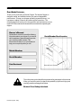
1
operator's manual INCLUDES SERVICE INFORMATION MODEL 8000 & 8100 CHIPPER PN-51210 (Rev. 7/98) W O O D S Dear Woods Customer, Thank you for purchasing a Woods Chipper. The Woods Chipper is designed, tested, and manufactured to give years of dependable performance. To keep your chipper operating at peak efficiency, it is necessary to adjust it correctly and make regular inspections. The following pages will assist you in the operation and maintenance of your machine. Please read and understand this manual before operating the chipper. Owner's Record Please take a moment to record the following information about your chipper. If you need to call for assistance, please be ready to provide your model and serial numbers. This information will allow us (or your dealer) to help you more quickly when you call. Serial Number Decal Location Model Number Serial Number Date Purchased Serial Number Decal This safety alert symbol identifies important safety messages in this manual. When you see this symbol, be alert to the possibility of personal injury and carefully read the message that follows. Be alert! Your Safety is Involved. PN-51210 (Rev. 7/98) C O N T E N T S Contents Safety Instructions .............................................................. 2 Safety Decals ............................................................................. 6 Assembly ........................................................................... 7 AttachChipperChute ................................................................... Attach Chute Extension Tray ......................................................... Attach Blower Discharge Tube ....................................................... Connect the Hydrostatic Control Cable ............................................. Connect PTO Shaft ...................................................................... 7 8 8 9 9 Controls ........................................................................... 10 Operation ......................................................................... 11 Starting ..................................................................................... 11 Chipping .................................................................................... 12 Stopping ................................................................................... 12 Service and Maintenance Schedule .................................... 13 Service and Maintenance................................................... 14 SharpeningChipperBlades ........................................................... 14 SettingChippingBladeClearance .................................................. 15 Adjusting or Replacing the Drive Belts ............................................ 16 ClearingPluggedRotor ................................................................ 16 Repairing or Replacing Rotor Bearings ............................................ 17 GreaseableBearings ................................................................... 18 Hydraulic Feed ................................................................. 19 Installing the Optional Hydraulic Feed Kit ........................................ 19 Hydraulic Feed Instructions .......................................................... 22 ControlArmOperation ................................................................. 23 HydraulicSchematic ................................................................... 23 HydraulicFeedMaintenance ......................................................... 24 HydrostaticPumpTroubleshooting ................................................. 24 Troubleshooting ............................................................... 25 Assembly Diagrams and Parts Lists ................................... 26 Service Accessories ................................................................... 26 Chute and Rotor Assembly Parts List ............................................. 26 ChuteandRotorAssemblyDiagram ............................................... 27 ChipperBaseAssemblyDiagram ................................................... 28 Chipper Base Parts List ............................................................... 28 Hyd. Feed Assy. Diagram and Parts.................................... 30 HydraulicFeedAssemblyDiagram ................................................. 30 Hydraulic Feed Parts List ............................................................. 32 Specifications .................................................................. 33 Warranty PN-51210 (Rev. 7/98) 1 S A F E T Y I N S T R U C T I O N S Safety Instructions This chipper is designed and tested to offer reasonably safe service. Failure to operate it in accordance with the following safety instructions MAY RESULT IN PERSONAL INJURY! A safety message alerts you to potential hazards that could hurt you or others. Each safety message is proceeded by one of three words: DANGER, WARNING, or CAUTION. DANGER You WILL be KILLED or SERIOUSLY HURT if you don't follow instructions WARNING You CAN be KILLED or SERIOUSLY HURT if you don't follow instructions. CAUTION You CAN be HURT or DAMAGE machine if you don't follow instructions. Before Operating • Read the owners manual before operating this equipment. • Do not allow children to operate this equipment. • Do not operate this equipment in the vicinity of bystanders. • Do not allow handsor any part of body or clothing inside the feeding chamber, discharge chute, or near any moving part. • Shut off the power source and make sure all moving parts are completely stopped before inspecting or servicing any part of the machine. • Wear safety glasses at all times while operating the machine. One pair is provided with each chipper. • Avoid wearing loose-fitting clothing. Never operate this machine wearing loose clothing particularly if it has drawstrings which can wrap around or get caught in the machine. • Operate the machine only on a level surface. • Do not operate the machine on a paved, concrete, or hard gravel surface. Operating on a hard surface causes discharged material to rebound and kickback. It will also cause increased machine vibration. Increased vibration causes the machine to move and will promote premature wear of parts or loosening of fasteners. Preparation PN-51210 (Rev. 7/98) 2 S A F E T Y I N S T R U C T I O N S • Visually check that all screws, nuts, bolts, and other fasteners are properly secured before starting the machine. Check all screws, nuts, bolts, and other fasteners once every 10 hours of operation for proper tightness to insure everything is in proper working condition. • Empty the cutting chamber before starting the machine. • Exclude pieces of metal, rocks, bottles, cans, and other foreign objects when feeding chipable material into the machine. • Shut off the engine or PTO and allow the machine to stop if the cutting mechanism strikes any foreign object or if the machine starts making an unusual noise or vibration. After machine stops: Operation a) Inspect for damage. b) Replace or repair any damaged parts. c) Check for and tighten any loose parts. • Do not allow processed material to build up in the discharge area; this may prevent proper discharge and result in kickback of material through the feed opening. • Do not allow hands or any other part of the body or clothing inside the feeding chambers, discharge chute, or near any moving part. • Keep all guards and deflectors in place and in good working condition. • Stand clear of the discharge area when operating this machine. • Keep your face and body back from the feed opening. • Do not over reach. Keep proper balance and footing at all times. • Do not transport or move machine while the machine is running. Disengage PTO and shut off tractor engine if the machine becomes clogged. Allow machine to come to a complete stop before clearing debris. WARNING: Keep body and clothing away from PTO shaft when running. • Connect 3 pt. hitch pins and snap pins, connect PTO shaft, and have leg stands solidly on the ground when in use. • Lock the rotor by inserting a bolt or punch through the locking holes on the side of the rotor housing before moving. To move unit: shut off PTO and lift 3 pt. hitch. • Keep guards and shields in place at all times while operating. Disengage tractor PTO and shut off engine before removing guards or shields. • Keep hands, feet, and clothing away from all PTO drive parts. • Never clean, lubricate, or adjust the chipper when it is running. PN-51210 (Rev. 7/98) 3 SA F E T Y I N S T R U C T I O N S • Put transmission in neutral or park and disengage before starting tractor. WARNING: This chipper is designed to be used with tractor PTO's rated at 20 to 60 horsepower. Using this chipper with PTO's above 60 horsepower may cause belt and machine damage in overload conditions. Additional Safety Rules for PTO Models PN-51210 (Rev. 7/98) 4 • Stay alert and pay attention when PTO chipper is operating. • Keep bystanders, especially children, away from the PTO driveline. • Connect 3 pt. hitch pins and snap pins, connect PTO shaft and have leg stands down and secure when in use. • Check the driveline to ensure it is attached securely to the tractor. • Keep guards and shields in place at all times while operating. Disengage tractor PTO and shut off engine before removing guards or shields. • Keep hands, feet, and clothing away from all PTO drive parts. • Do not clean, lubricate, or adjust the PTO when it is running. • Clothing worn by operator must be fairly tight. Never wear loose jackets, shirts, shirt sleeves or pants when working around PTO. Tie long hair back or put under a cap. S A F E T Y I N S T R U C T I O N S • Keep hydraulic hoses, electric cords, chains, and other items from contacting the driveline. • Make sure transmission is in neutral or park and PTO is disengaged before starting the tractor. • Do not exceed the recommended 540 RPM PTO operating speed. • Disconnect PTO and shut off tractor when this unit is stopped for servicing, inspection, storage, or to change an accessory. • Shut off the PTO, lift 3 pt. hitch, and adjust leg stands if needed to move the unit. • Read and follow instructions on PTO safety decals. WARNING! Recommended tractor PTO horsepower is 15 HP to 30 HP. Use of these units on tractors above 30 PTO horsepower may cause belt and machine damage in overload conditions. Safe Storage • Disengage PTO when this equipment is stopped for servicing, inspection, storage, or to change an accessory. • Store the machine out of reach of children. Clear debris from inside the machine and store in a dry area for storage periods of three months or more. PN-51210 (Rev. 7/98) 5 SAFETY DECALS Safety Decals Safety and instruction decals are located on the chipper frame and engine. Replace any damaged or unreadable decal. NOTE: See parts drawings and lists for location of safety decals on the chipper frame. PN 57835, French Safety Decal Kit PN 51284 PN 51361 PN 51281 PN 51373 PN 51375 PN 51312 PN-51210 (Rev. 7/98) 6 A S S E M B L Y Assembly For instructions on assembling the hydraulic feed kit, see page 20. Attach Chipper Chute Do not operate this unit without the chipper chute correctly installed. Rotating cutting blades can cause serious personal injury. 1. Remove chipper from shipping crate. Place unit on a level surface before attempting to assemble. See torque chart for minimum tightening torque. Torque Chart Standardminimum tightening torque for normal assembly applications. 2. Mount the chipper chute to the frame mounting bracket using eight 3/8" x 1" bolts and locknuts. Use three bolts on each side and two on the bottom (see figure 1). Attach the chute directly to the hydraulic feed unit as described above for models with factory-installed hydraulic feed. Bolts (SAE GR5) Size 5/16" 3/8" 1/2" Ft. Lbs. 20 35 75 Screws Size 5/16" Set Ft. Lbs. 15 Chipper Chute Chipper Frame Figure 1 PN-51210 (Rev. 7/98) 7 A S S E M B L Y Attach Chute Extension Tray 1. Slide the chute extension tray over the chipper chute as shown in figure 2 after mounting the chute to the chipper frame. Make sure you position the lip on the extension tray behind the lip on the chipper chute. Align the five bolt holes in the chute extension tray with the bolt holes in the hinge. 2. Insert five 3/8" x 1" carriage bolts (included in owners kit packaged with the chipper) through the tray and the extension hinge. Secure the bolts with washers and nuts. Secure with hairpin clips. Attach Blower Discharge Tube 1. Attach the blower discharge tube to the mounting flange on the chipper frame (see figure 3). Half of the mounting clamp is already attached to the tube. Slide the tube into the flange and tighten the bolts to secure it. Install the second half of the clamp to the tube and flange. Rotate the tube 360 degrees and lock it in place with the handle to make sure it is mounted correctly. Hairpin Clip s Extension Tray Position this lip behind the lip on the chipper chute shown below. Hold the extension tray directly above the chipper chute and slide it downward. Blower Discharge Tube Mounting Clamp Feed Control Lever (Models with hydraulic feed only.) Mounting Flange s Chipper Chute s Extension Hinge Figure 2 PN-51210 (Rev. 7/98) 8 Figure 3 A S S E M B L Y Connect the Hydrostatic Control Cable (For models with factory installed hydraulic feed.) 1. Remove the clevis assembly from the hydrostatic control cable end (see figure 4). Remove one nut on the cable end. Insert the cable end into the hole in the cable anchor weldment. Replace the nut and the clevis assembly. 2. Attach the clevis assembly to the center hole on the feed control lever. 3. Adjust the cable detent ball to contact the detents in the cable anchor weldment when the control arm is in the forward position or reverse position. Important! See hydrostatic pump start-up procedure. Connect PTO Shaft 1. Connect the PTO shaft female end to the rotor shaft using key stock and two set screws contained in the owner's kit. 2. Connect the opposite end of the PTO shaft to the tractor. 3. Check all screws, bolts, and nuts for tightness. See torque chart, page 5 for minimum tightening torque. Insert cable through hole Nut Clevis Assembly Detent Ball Feed Control Lever Cable Anchor Weldment Hydrostat Control Cable Figure 4 PN-51210 (Rev. 7/98) 9 CONTROLS Controls (see figure 5) 1. Three pt. Hitch Connection: Mounts chipper to tractor 3 pt. hitch. Connect direct for category 1. 2. PTO Shaft: Connects chipper to tractor PTO shaft. Avoid driveline angles over 20 degrees on PTO shaft when unit is in use. 3. Drive Belt Shield: Never remove shield while machine is running. 4. Chipper Chute: Feeds materials to the chipper blades for chipping. 5. Leg Stands: Never move machine unless legs are in UP position and clear the ground. 6. Rotor Access Cover: Tilts up to remove chipper blades and to service rotor assembly. 7. Discharge Tube: Chipped materials will exit through this tube. Tube is adjustable 360 degrees. 8. Adjustable Chipping Anvil: Adjusts to vary the size of chips. 9. Rotor Shaft Bearing Cover: Rotor shaft has lock assembly to lock rotor in place while moving. PTO Model Controls Figure 5 7 6 4 9 3 2 1 5 PN-51210 (Rev. 7/98) 10 8 O P E R A T I O N Operation CAUTION: Wear safety glasses at all times when operating the machine. Do not wear loose fitting clothing. The operator should always wear heavy boots, gloves, pants, and shirt. Use common sense and practice safety to protect yourself from branches, sharp objects, and other harmful objects. NOTE: The heavy rotor continues to turn for some time after the tractor has been shut off. The rotor is stopped when no noise or machine vibration is present. Inserting a branch into the chipper chute to contact the blades slows the rotor and shortens stopping time. NOTE: Minimum and maximum telescoping on the PTO shaft is 20-28 inches. This will leave 4 inches overlap at maximum telescoping distance (see figure 6). Starting 1. Place tractor transmission in park or neutral and set parking brake. Connect 3 pt. mounts between the chipper and tractor. Secure connections with snap pins. Adjust 3 pt. top link so chipper sits level. 2. Connect PTO shaft to tractor. Make sure you are using the correct RPM machine. Do not operate machine at speeds different than specified on shield. 3. Do not inspect or work on PTO drive area without first disengaging PTO and shutting off tractor engine. 4. Start tractor engine and engage PTO drive clutch (see tractor owner's manual). Increase engine speed to rated PTO RPM position. WARNING: This chipper is designed to be used with tractor PTO's rated at 20 to 60 horsepower. Using this chipper with PTO's above 60 horsepower may cause belt and machine damage in overload conditions. Figure 6 Telescoping Type 20 to 28 inches will leave at least 4 inches overlap PN-51210 (Rev. 7/98) 11 O P E R A T I O N Chipping WARNING: Keep face and body away from the feed opening. Do not over reach. Keep proper balance and footing at all times. The Woods chipper is designed to chip a variety of materials into a more readily decomposing or handled condition. The following guidelines can be used to help you get started. Please read and follow all safety instructions in this manual. Failure to operate the chipper in accordance with the safety instructions MAY RESULT IN PERSONAL INJURY! • Be sure the unit is at full operating speed before starting to chip material. • Select limbs up to 8 inches in diameter. Trim side branches that cannot be bent enough to feed into the chipper chute. Hold small diameter branches in a bundle and feed simultaneously. • Feed brush from the side of the infeed chute rather than from the front. Step aside to avoid being hit by brush moving into the chipper. • Never lean into the infeed chute to push objects into the cutting device. Use a push stick or brush paddle. • Do not use shovels or forks to push brush. They can go through the chipper, are expensive to replace, and cause major damage. Metal pieces can come back like shrapnel to injure or kill. • Never push brush into the infeed chute with your feet. • Place limb, butt end first, into the chipper chute until it contacts the chipper blades. The actual feed rate of the limb into the chipper will depend on the type of material fed and sharpness of the cutting blades. • Alternately insert and retract the limb or insert continuously at a rate that will not stall the tractor. Rotating the branch as you feed it will improve cutting action. NOTE: The chipping blades dull with use and require periodic sharpening. Refer to service and maintenance, "sharpening chipper blades" for instructions. Stopping WARNING: Do not leave machine unattended, or attempt any inspection or service unless PTO is disengaged and tractor engine is shut off. Allow machine to come to a complete stop. To stop machine, proceed as follows: 1. Move tractor throttle to SLOW position. 2. Disengage PTO lever and shut off tractor engine. 3. Allow machine to come to a complete stop. PN-51210 (Rev. 7/98) 12 NOTE: The heavy rotor continues to turn for some time after the engine or tractor has been shut off. The rotor is stopped when no noise or machine vibration is present. Inserting a branch into the chipper chute to contact the blades slows the rotor and shortens stopping time. SERVICE A N D M A I N T E N A N C E S C H E D U L E Service and Maintenance Schedule Before Each Use Inspection Items Every 10 Hours Every 25 Hours Every 50 Hours Interval Every Every 100 200 Hours Hours Every 300 Hours Every 800 Hours Every 1 years Check Nuts & Bolts (Entire machine) Check Replace Check Hydraulic Filter Element Clean * Replace Check Hydraulic Control Cable Check Sharpness of Chipper Blades Grease Bearings and Pivots Check Bolts: Chipper Blade, Chipper Anvil, Rotor Paddles Check Drive Belt Clean Machine Note: (*) Service more frequently when used in dusty conditions Before inspecting or repairing any part of the machine, shut off the engine and make sure all moving parts have come to a complete stop. Indicates first hours of use. PN-51210 (Rev. 7/98) 13 SERVICE AND MAINTENANCE Service and Maintenance WARNING: Shut off PTO and make sure all moving parts have come to a complete stop before inspecting or servicing any part of the machine. The chipping blades are sharp! Use care when working on machine to avoid injury. WARNING: The rotor assembly has a lock mechanism. Use the lock mechanism at all times when working on the rotor assembly. Remove plastic bearing cover under chipper chute. There is a hole in the rotor jack shaft and a matching hole in the bracket mounted to the rotor bearing front side. Install a punch through the rotor shaft and bracket to lock the rotor in place. Sharpening Chipper Blades The chipper blades dull, making chipping difficult. It is recommended to sharpen the chipper blades every 5-15 hours of chipper operation. To remove the chipping blades for sharpening: 1. Remove the two 3/8" retaining bolts holding access cover to main frame assembly. 2. Tilt access cover over to allow rotor access. Rotate the rotor so the bolts holding a chipping blade are most accessible. 3. Remove the two allen head bolts holding the blade itself. Repeat for all four blades. The four chipping blades have two edges per blade and can be reversed one time each before sharpening. Remove and reverse the chipping blades if both sides have not been used. Reinstall chipping blades and proceed with chipping. To grind the angled edge of the chipping blade to 45 degrees (see figure 7): Grind the blades on a slow-speed wet grinder, if possible, or have them Sharpening Edges t 45⋅⋅ t s 0.38 Figure 7 Figure 8 PN-51210 (Rev. 7/98) 14 t S You do not have to remove the rotor from the main frame to repair the chipper blades or paddles located on the back of the rotor assembly. E R V I C E A N D M A I N T E N A N C E sharpened by a professional. Be careful when grinding if using a bench grinder so the blade material does not get too hot and change colorthis will remove the blade's special heat treated properties. Use short grinding times and cool with water. Remove an equal amount off each blade to maintain balance. Replace the chipping blades and tighten bolts to 75 ft. lbs. Close cover and replace bolts. Chipping Blade Sharpening Tips Poor chipping performance is usually a result of dull chipping blades. Check for the following symptoms if chipper performance has decreased: Severe vibration when feeding material into the chipper. Small diameter branches do not self-feed. Chips discharge unevenly or have stringy tailsespecially when chipping green branches. Check for permanent damage before you sharpen the chipping blades. Replace the blade if: The blade is cracked (especially around the bolt holes) or the edges are too deeply chipped to be ground smooth. The base of the cutting edge is worn or has been re-sharpened so it is too close to the rotor chipping slot. Setting Chipping Blade Clearance The four-edged chipping anvil located directly under the chipper chute should clear the chipping blade by 1/16 inch to 3/16 inch. The chipping anvil is adjustable and reversible. To Adjust: 1. Lift rotor access cover and expose rotor (see figure 8, page 12). Loosen the three 1/2" bolts holding the chipper anvil to the frame. 2. Measure the amount of clearance between chipping blade and chipping anvil from inside of housing. 3. Adjust inward or outward to desired measurement. 4. Tighten bolts on chipping anvil to 75 ft. lbs. and resume operation. Remove the three bolts holding the anvil and use one of the other three edges if the chipping anvil edge is damaged or worn unevenly. Adjust for correct measurement. PN-51210 (Rev. 7/98) 15 SERVICE A N D MAINTENANCE Adjusting or Replacing Drive Belts Check the condition of the drive belts annually or after every 30 hours of operating, whichever comes first. Replace cracked, frayed, or worn belts. Proceed as follows to replace or adjust the drive belt: 1. Disengage PTO and shut off tractor engine. 2. Remove PTO shaft from tractor; disconnect machine from 3 pt. hitch. 3. Remove round shield connected to belt guard covering the PTO shaft by removing two 5/16" nuts. 4. Remove PTO shaft from chipper by removing two set screws and pulling shaft off. 5. Remove belt guard covering pulleys and belts. 6. Lift spring loaded idler pulley off of belt and remove belt. 7. Install new belt and reverse above instructions to complete belt replacement. Clearing Plugged Rotor WARNING: Shut off the tractor engine and allow the machine to completely stop before clearing debris if the machine plugs. Do not operate the machine without proper guards and screens in place. The chipper can plug if too large or too much material is fed into it. Proceed as follows to clear plugged rotor: 1. Disengage PTO and shut off tractor engine. 2. Lift rotor access cover. 3. Clean the debris out of the chipping rotor. Turn the rotor by hand to be sure it is free to rotate. 4. Replace rotor access cover. 5. Start tractor, engage PTO, and resume operation. PN-51210 (Rev. 7/98) 16 S E R V I C E A N D M A I N T E N A N C E Repairing or Replacing Rotor Bearings 1. Remove two 3/8" retaining bolts holding access cover to main frame assembly. Tilt access cover over to allow rotor access. 2. Remove large belt guard (three 5/16" bolts). 3. Loosen bolts on hydraulic pump and remove hydraulic pump belt. Remove the bushing and pulley from the rotor shaft using the push bolts from the bushing. 4. Lift belt idler pulley off drive belt and remove belt from pulleys. Remove the bushing and pulley from the rotor shaft using the push bolts from the bushing. WARNING: The rotor assembly has a lock mechanism. Use the lock mechanism at all times when working on the rotor assembly. Remove plastic bearing cover under the chipper chute. There is a hole in the rotor jack shaft and a matching hole in the bracket mounted to the rotor bearing front side. Install a punch through the rotor shaft and bracket to lock the rotor in place. 5. Remove four 1/2" bolts on each rotor bearing and remove punch used to lock the rotor. 6. Lift the rotor assembly completely out of the frame using an overhead hoist or lifting device. The complete rotor assembly weighs 275 lbs. 7. Remove 3/8" bolts and collar from front once the rotor assembly is out of the frame. Remove both bearings with a puller and place new bearings on rotor shaft. Replace collar. 8. Return the complete rotor assembly to the chipper frame with an overhead hoist or lifting device. 9. Slide rotor back until front collar is tight against the front bearing. Lock the front bearing and install four 1/2" bolts on each bearing to secure them to the frame. Tighten bolts to 75 ft. lbs. Check and adjust chipper anvil if needed. Lock rear bearing. 10. Slide rear collar on shaft against rear bearing. Slide bushing onto shaft with flange against collar and lock bushing to shaft. Attach large pulley to bushing. Replace drive belt on pulleys and lower belt idler. Check alignment of pulleys and adjust engine if needed. 11. Close cover and replace bolts. 12. Replace hydraulic pump bushing and pulley. Replace hydraulic pump belt. Readjust hydraulic pump belt tension by sliding the hydraulic pump in the mounting slots. Tighten bolts. 13. Replace belt guard and resume operation. 14. Start tractor engine and engage PTO drive clutch (see tractor owner's manual). Increase engine speed to rated PTO RPM Position. Test unit, readjust pulleys, and belt tension if needed. PN-51210 (Rev. 7/98) 17 SE R V I C E A N D M A I N T E N A N C E Important! Check the bolts on the following for correct torque (75 ft. lbs.) every 10 hours of operation: Hydraulic feed roller bearing Hydraulic motor mounting Chipper rotor bearing Chipper blades Rotor paddles Chipper anvil Warning: Failure to maintain proper fastening torque (75 ft. lbs.) on bolts for the components listed above may result in severe damage to the chipper and/or personal injury! Greaseable Bearings The PTO model has ten grease zerks. Minimal periodic greasing is needed on these points every 50 hours: PN-51210 (Rev. 7/98) 18 Four grease zerks on the PTO shaft itself. Two greaseable bearings on the rotor shaft. Two greaseable bearings on the bottom jack shaft. One idler arm pivot One discharge chute HYDRAULIC FEED INSTALLATION Hydraulic Feed Installing the Optional Hydraulic Feed Kit (For models without factory installed hydraulic feed.) Install the Roller Assembly 1. Remove the bolts fastening the chipper chute to the rotor housing weldment. 2. Remove the chipper chute mounting plate. 3. Hold the roller assembly up to the rotor housing weldment. Secure the roller assembly with 3/8" x 1-1/2" bolts, washers, and nuts. 4. Attach the chipper chute to the roller assembly with 3/8" x 1-1/2" bolts, washers, and nuts. Attach the Control Arm 1. Remove the canvas chipper chute flap and angle. 2. Fasten the cable anchor to the chipper chute with 3/8" x 1-1/4" bolts, washers, and nuts. 3. Attach control pivot and extension hinge to the chipper chute bottom with 3/8" x 1-1/2" bolts, washers, and nuts. 4. Put three 5/8" washers on both control pivot shafts. 5. Place the control arm shaft holes over the control pivot shafts. 6. Place a 5/8" bearing over each pivot shaft and fasten each bearing to the control arm with two 3/8" x 1" bolts and nuts. 7. Attach the feed control lever to the cable anchor weldment by inserting a 5/16" x 2" bolt through the bolt holes. Place the drift cutter spring over the end of the bolt. Secure the bolt and spring with a 5/16" washer and nut. 8. Put the detent ball into the detent cavity on the feed control lever. Insert the detent spring into the detent cavity. Secure the spring and the ball by threading a 3/8" x 1" bolt through a 3/8" nut and then threading the bolt into the detent cavity. 9. Connect the control arm to the feed control lever with the control tie rod strip. Place a 5/16" washer and an idler pivot spacer over a 5/16" bolt. Insert the bolt through the bolt hole in one end of the control tie rod strip and the top bolt hole on the feed control lever. Secure the bolt with a 5/16" washer and nut. Insert a 5/16" x 1" bolt (with a 5/16" washer and idler pivot spacer) through the other bolt hole in the control tie rod strip and the control arm. Secure with a 5/16" washer and nut. PN-51210 (Rev. 7/98) 19 HYDRAULIC FEED INSTALLATION Install the 6.6" Pulley 1. Remove the chipper drive belt guard. 2. Put the 6.6" pulley on the rotor shaft end. 3. Place the 1.75" bushing on the rotor shaft and put the 3/8" x 1/4" key into the bushing slot. Do not tighten the bushing yet. Mount the Hydrostatic Pump 1. Attach the pump control arm to the pump control on the hydrostatic pump with two 1/4" x 1/2" bolts. 2. Mount the pump mount bracket to the hitch weldment by inserting two 3/8" x 1-1/2" bolts through the bolt holes. Place the cable attachment angle over the bolt ends on the other side of the hitch weldment. Secure the bolts with two 3/8" washers and nuts. 3. Slide the 4" pulley over the pump shaft. Slide the 15mm bushing next to the pulley. Place the 5mm x 25mm key into the bushing. Do not tighten the bushing yet. Connect the Hydrostatic Cable 1. Insert the hydrostatic control cable end (the end without nuts attached) through the cable hole in the hitch weldment. Figure 9 Roller Assembly Hydrostatic Motor Crossover Relief Valve PN-51210 (Rev. 7/98) 20 HYDRAULIC FEED INSTALLATION 2. Thread the cable end into the cable pivot pin. Insert the pivot pin into the hole in the pump control arm. Secure the pivot pin with a 1/4" washer and a 3/32" x 3/4" cotter pin. 3. Place the cable clamp shim and clamp on the cable exterior (as shown on page 20). Secure the cable, clamp, and shim to the cable attachment angle with two 1/4" x 3/4" bolts and locknuts. 4. Remove one nut on the opposite cable end. Insert the cable end into the hole in the cable anchor weldment. Replace the nut. 5. Attach the clevis assembly to the center hole on the feed control lever. Attach the Valve and Mount the Reservoir 1. Attach the crossover relief valve to the chipper stand with two 3/8" x 2" bolts, washers, and nuts. 2. Attach the reservoir support weldment to the chipper rotor housing with two 5/16" x 3/4" bolts, washers, and nuts. 3. Put the tank on the reservoir support. 4. Place the reservoir straps over the tank and secure with 5/16" x 3/4" bolts, washers, and locknuts. Connect the Belt 1. Attach the belt to the 6.6" rotor shaft pulley and the 4" hydrostatic pump pulley. 2. Align the two pulleys with a straight edge. 3. Tighten both pulley bushings. 4. Move pump to tighten belt. 5. Install the hydraulic hoses as shown on page 20. Follow hydrostatic pump start up and maintenance instructions on pages 20 and 21. 6. Replace chipper drive belt guard. 7. Install chute extension tray as described on page 6. PN-51210 (Rev. 7/98) 21 HYDRAULIC FEED OPERATION INSTRUCTIONS Hydraulic Feed Operating Instructions Fluids Handle pressurized hydraulic fluid carefully. Escaping pressurized hydraulic fluid has sufficient force to penetrate skin causing serious injury. This fluid may also be hot enough to burn. Serious infection or reactions can develop if proper medical treatment is not administered immediately. Premium hydraulic fluids containing high quality rust, oxidation, and foam inhibitors are required. These include premium turbine oils, API CD engine oils per SAE J183, M2C33F or G automatic transmission fluids meeting Allison C-3 or Caterpillar TO-2, and certain specialty agricultural tractor fluids. Hydrostatic Pump Start Up Procedure Hydrostatic pressure controlled by the crossover relief valve is factory set at 1750 PSI. A 2000 PSI shim kit is available for extreme conditions. Follow this start-up procedure to start a new installation or to restart an installation if the hydrostatic pump was removed from the system. 1. Make sure all system components (reservoir, fittings, etc.) are clean before starting the hydrostatic pump. 2. Fill the reservoir with recommended hydraulic fluid (filter before filling). 3. Fill the inlet line leading from the reservoir to the charge pump before start-up. Loosen the fitting on this inlet line until oil bleeds out. Warning! Do not start engine unless pump is in neutral or detent position on the cable. 4. Start the engine and run at the lowest possible RPM. 5. Refill the reservoir as necessary. The oil level in the reservoir drops and bubbles appear in the fluid as air purges from the unit. 6. Run the unit in both directions for several minutes until any remaining air is purged from the unit. Refill the reservoir as necessary. 7. Loosen a motor fitting and oil-bled to remove air from the system (use same procedures as steps 3-5) if needed. 8. Disengage PTO, check for and correct any fluid leaks, and check the reservoir level. Add fluid if necessary. • Figure 10 Pump-Component Locations The hydrostatic pump is now ready for operation. Charge Pump Charge Check Valve Control Shaft Seal Bypass Valve PN-51210 (Rev. 7/98) 22 Input Shaft Seal HY F D R A U L I C E E D OP E R A T I O N I N S T R U C T I O N S Control Arm Operation 1. Engage the PTO. Bring the chipper up to operating speed. See the operation section for starting, operation, and stopping instructions. 2. Engage the hydraulic feed by moving the control arm as shown in figure 11 below. The feed rate increases as the arm is moved in the forward direction. 3. Feed the branch (up to eight inches in diameter). 4. Reverse the feed by moving the control arm in the reverse direction if the chipper jams. Remove the branch and rotate it before reinserting it into the chute. Neutral s Reverse s Please read and follow all safety instructions in this manual. Failure to operate the chipper in accordance with the safety instructions MAY RESULT IN PERSONAL INJURY! Forward Feed Control Lever Figure 11 Hydraulic Schematic Parts listed on page 28. PN-51210 (Rev. 7/98) 23 HYDRAULIC FEED M A I N T E N A N C E Hydraulic Feed Maintenance NOTE: Check the reservoir daily for proper fluid level, the presence of water (noted by a cloudy to milky appearance or free water in bottom of reservoir), and rancid fluid odor (excessive heat). The hydrostatic pump normally does not require regular fluid changes. Change the system filter at 250 hour or annual intervals. Change the fluid and filter and clean the system if the fluid becomes contaminated with foreign matter (water, dirt, grease, etc.) or if the fluid has been subjected to temperature levels greater than the recommended maximum. There is a greaseable bearing on each side of the main jack shaft on the main hydraulic feed housing. Grease periodically. Hydrostatic Pump Troubleshooting Contact your dealer or factory service department Before servicing or repairing any of the hydrostatic feed components (pump, motor, and/or relief valve). Warranty on these items may be void without prior authorization. Symptom Probable Cause Will not attain normal feed rate. Engine not operating at correct speed. Control linkage damaged or binding. Bypass valve stuck partially open. (Problem in one direction only.) Repair engine governor. Control linkage damaged or not connected. Drive between engine and pumpdamaged. Repair or reconnect control linkage. Repair drive (replace broken belt, repair sheared key, repair splined coupling, etc.). Refill reservoir. Purge air from transmission. Will not feed when control arm is moved. Pump low on fluid. Feed rate is sluggish under load. Loose drive belt between engine and pump. Pump low on fluid. Large amount of water in hydraulic fluid (evaporates when hot, resulting in low fluid level). Hydraulic Feed will not pull in logs over 4" in diameter, or continuously stalls or stops. PN-51210 (Rev. 7/98) 24 Hydraulic system overloading and causing system to go over relief Suggested Remedy Repair control linkage. Repair bypass valve. Remove foreign material from valve. Tension drive belt (replace if necessary). Refill reservoir. Purge air from transmission if necessary. Drain fluid from reservoir and unit, replace filter element, and refill with new fluid. Check relief pressure in system with a pressure gauge rated to 2500 psi. (System set by factory at 1750 psi.) T R O U B L E S H O O T I N G Troubleshooting Problem Probable Cause Suggested Remedies Reference 1. Rotor does not turn a) Obstructed discharge. a) Use branch or similar object to clear discharge. b) Clear rotor. Service and Maintenance a) Use branch or similar object to clear discharge. b) Sharpen blades. c) Adjust clearance. Service and Maintenance a) Use branch or similar object to clear discharge. b) Clear rotor, feed material into shreddermore slowly. c) Alternately feed dry material, or allow material to dry. Service and Maintenance Service and Maintenance b) Plugged rotor. 2. Hard to feed chipper or excessive power needed to chip a) Obstructed discharge. 3. Chipper requires excessive power or stalls a) Obstructed discharge. b) Dull chipper blades. c) Improper blade clearance. b) Plugged rotor. c) Green material will not discharge. 4. Drive belts squealing or smoking a) Plugged rotor. b) Loose or worn belts. a) Clear rotor. b) Adjust belt tension or replace belts if needed. 5. PTO will not turn or has slow RPM's a) PTO shaft not engaged on tractor. b) PTO shaft loose. a) Engage PTO. 6. Vibration while running a) Drive shaft vibration. a) Check drive belts and pulleys for bad or worn spots. Check PTO shaft for wear. b) Inspect rotor for broken or missing chipper blades and paddles. Repair if needed. c) Check rotor to see if it wobbles. d) Check to see if rotor is assembled correctly. b) Rotor out of balance. b) Check all connections and repair if needed. Service and Maintenance Service and Maintenance PN-51210 (Rev. 7/98) 25 CHUTE AND ROTOR ASSEMBLY PARTS LIST Chute and Rotor Assembly Part List No. Part No. 1. 2. 3. 4. 5. 6. 7. 8. 9. 10. 11. 12. 13. 14. 15. 16. 17. 18. 19. 20. 21. 22. 23. 24. 25. 26. 51458 51474 51459 51460 51464 51461 51462 51463 51682 51982 51506 51507 51557 51467 51468 51469 51472 51473 51470 51471 51554 51373 51374 51375 51361 51284 12650 Description Qty. Disk, Chipper 1 Collar, Chipper Lock 1 Blade, Chipper 4 Paddle, Big Chipper 4 Weldment, Chipper Rotor Shaft 1 Plate, Chipper Bottom 1 Base, Chipper Chute 1 Bearing Bracket, Right 1 Decal, Woods 8000 Chipper 1 Decal, Woods 8100 Chipper 1 Assy, Top Housing (#23,29, 34, 55 Incl.) 1 Assy, Chipper Chute (#21 Included) 1 Assy, Chipper Discharge (#29 Included) 1 Ring, Discharge Spacer 2 Ring, Discharge Clamp 2 Lever, Discharge Lock 1 Angle, Flap Anchor 1* Flap, Chipper Chute 1* Weldment, Dis. Lock Pin 1 Tube, Discharge Lock Pivot 1 Deflector, Blower Discharge 1 Danger, Decal 2 Decal, Made in USA 1 Decal, Operating Instructions 1 Danger Decal 1 Decal, Access Cover 1 Screw, #6 x 1/2" Drive 2 No. 27. 28. 29. 30. 31. 32. 33. 34. 35. 36. 37. 38. 39. 40. 41. 42. 43. 44. 45. 46. 47. 48. 49. 50. 51. 52. 53. 54. 55. Part No. 51514 51311 51312 51310 51484 51489 3379 N/A 51301 51261 3699 854 765 1093 58782 12169 2290 565 28093 51239 1059 4378 71061 6697 3597 639 51270 58776 58775 Description Qty. Grease Zerk 1/4" Drive Ball 1 Spring, Lock Compression 1 Decal, Discharge 2 Bearing, 1-3/4 4 Bolt Flange 1 Shaft, Chipper Top Pivot 1 Strip, Flap Retainer 1* Bolt, 1/2 x 1-1/2" GR5 Hex Capscrew 3 Serial Number Decal 1 Cap, Large Shaft 1 THD Stud 1/2"-13 X 3" LG, B7, ZP 2 Bolt, 1/2 X 2" G5 Hex Capscrew, ZP 14 Washer, 1/2" Flat ZP (56PC/LB) 6 Nut, 1/2 Center Locknut 30 Nut, Hex Nut NC, ZP 2 Screw, 1/2 X 2" FLT HD SKT 8 Bolt, 3/8 X 1-1/4" HHCS GR5 ZP 12 Bolt, 3/8 X 2-1/2 GR5 Hex HHCS ZP 1 Washer, 3/8" FLT ZP-140PC/LB 24 Locknut, 3/8" NYL Insert, NE, ZP 25 Bolt, Carr 3/8" X 1-1/2" GR5 NC, ZP 10 Bolt, 5/16 X 2-1/2" G5 HX CAP ZP 1 Washer, 5/16" FLT ZP (195PC/#) 1 Locknut, 5/16 NYL, NC, TYP NE, ZP 1 Bolt, 3/8" X 1" Carriage GR5 ZP 4 Cotter Pin, 1/8 X 1.00 ZP 3 Bolt, 1/2 X 2-1/2" Hex HD 6 Spout Knob, 5/16-18 2 Spacer, Anvil 1 Decal, Check Bolts 1 * Not used on hydraulic feed models Service Accessories Part # Description 51222 Chipper blade kit for PTO and towable models. Includes four chipper blades and replacement bolts and nuts. 51315 Set of three matched belts for PTO model 57835 French Safety Decal Kit PN-51210 (Rev. 7/98) 26 CHUTE AND ROTOR ASSEMBLY DIAGRAM Chute and Rotor Assembly Diagram PN-51210 (Rev. 7/98) 27 CHIPPER BASE ASSEMBLY Chipper Base Assembly Diagram Chipper Base Parts List No. Part No. 1. 51505 2. 51465 3. 51466 4. 51475 5. 51570 6. 51273 7. 81286 8. 51314 9. 51234 10. 51224 11. 51315 Description Assy, Chipper Bottom Jackshaft, Chipper Drive Weldment, PTO Stand Hitch Support Weldment Spacer, RH Bearing, 2 BLT FLG 1-1/2" Bore Pulley, Idler 5" X 2.50" Sheave, 3B 13.6 SK Sheave, 3B4.8 SD Bushing SK1.5 Belt, BX 64 (Matched Set of 3) PN-51210 (Rev. 7/98) 28 Qty. 1 1 1 1 1 2 1 1 1 1 1 No. 12. 13. 14. 15. 16. 17. 18. 19. 20. 21. 22. Part No. 51514 608 51279 51280 51276 51281 51316 51367 51310 51483 51481 Description Grease Zerk 1/4" Drive Ball Key, 3/8" SQ X 2" LG Plain Pin, Lift Arm 7/8 X 5" LG Pin, Top Link 3/4 X 4-1/2" LG Pin Lynch 7/16 X 5/8" Decal, 540 PTO Danger Driveshaft, 540 PTO Chipper Spring, Ext. 3/4" OD Bearing, 1-3/4 4 Bolt Flange Weldment, Left Bearing Bracket Weldment, Lower Belt Guard Qty. 2 3 2 1 3 1 1 1 2 1 1 CHIPPER No. Part No. 23. 51405 24. 51508 25. 51322 26. 51419 27. 51480 28. 51490 29. 51503 30. 51504 31. 3379 32. 3699 33. 1637 Description Qty. Spacer, .75 X 1.18 1 Assy, Upper Belt Guard & Decal (17) 1 Bushing, SD 1-3/4" 1 Joint Shield Weldment 1 Weldment, Idler Arm 1 Cover, Hose Access 1 Shield, Shaft 1 Plate, Spring Anchor 1 Bolt 1/2 X 1-1/2 GR5 Hex Capsw Zp 9 Bolt, 1/2 X 2 GR5 Hex Capscrew Zp 10 Bolt, 1/2 X 3-1/2 GR5 HCS ZP 1 No. 34. 35. 36. 37. 38. 39. 40. 41. 42. 43. 44. 45. 46. Part No. 854 765 565 28093 14562 4378 71061 839 12735 12169 51361 58777 15131 BASE ASSEMBLY Description Qty. Washer, 1/2" Flat ZP (56PC/LB) 25 Nut, 1/2" Center Lock 1 Washer, 3/8" FLT ZP-140PC/LB 21 Locknut, 3/8" NYL Insert, NE, ZP 26 Bolt, 5/16 X 1" GR5 HHCS NC ZP 10 Washer, 5/16" FLT ZP (195PC/#) 19 Locknut, 5/16" NYL, NC, TYP NE, ZP 5 Bolt, CARR 1/2 X 1-1/2" GR5, ZP 2 Bolt, CARR 1/2 X 1-1/2" GR5 ZP 2 Bolt, 3/8 X 3-1/4" HXHD GR5 ZP 1 Danger Decal 1 Wldmt, Pickup Sprocket 1 Screw, 5/16" x 5/8" Cup PT 1 PN-51210 (Rev. 7/98) 29 HYDRAULIC FEED ASSEMBLY DIAGRAM Hydraulic Feed Assembly Diagram PN-51210 (Rev. 7/98) 30 HYDRAULIC FEED ASSEMBLY DIAGRAM PN-51210 (Rev. 7/98) 31 HYDRAULIC FEED PARTS LIST Hydraulic Feed Parts List No. 1. 2. 3. 4. 5. 6. 7. 8. 9. 10. 11. 12. 13. 14. 15. 16. 17. 18. 19. 20. 21. 22. 23. 24. 25. 26. 27. 28. 29. 30. 31. 32. 33. 34. 35. 36. 37. 38. 39. 40. 41. Part No. 51476 51477 51479 51478 51486 51487 51256 51522 51493 51494 51495 51393 51496 51497 51498 51485 51492 51491 51510 51240 51507 51432 51304 51317 51262 51318 51263 51319 51271 51287 51320 51321 51306 51330 51237 51254 51380 51329 51245 51242 51768 51246 51238 51365 51366 Description Weldment, Roller Support Weldment, Top Grab Roller Weldment, Roller Slide Bearing, Roller Slide Weldment, Top Roller Cover Shield, Coupler Coupler 1-1/4" Shaft Weldment, Control Pivot Weldment, Control Arm Weldment, Cable Anchor Weldment, Feed Control Lever Spacer, Idler Pivot Strip, Control Tie Rod Weldment, Pump Control Arm Angle, Cable Attachment Bracket, Pump Mount Strap Reservoir Weldment, Reservoir Support Cover, Reservoir Base Bolt, 5/16" x 2" GR5 HCS ZP Assy, Chipper Chute (Inc. #43) Spacer, 0.75 X 0.620 Sheave, 1B5.2 SDS Pump, Hydrostatic Kit Hydrostatic Pump Seal Motor, 45 Cu. In. Hydraulic Kit White Motor Seal Valve, Crossover Relief Kit, Relief Cartridge Seal Kit, 2000 PSI Relief Shim Filter, Spin-on Tank, Oil Reservoir Sheave, 1B3.6 SH Bushing, 1.75 SDS Bushing, 15mm SH Bearing, 1-1/4" Dia. 2 Bolt Flng. Bearing, Side Flng. Mount, 5/8" Cable, Hydrostat Control Cable Pivot Pin Clevis Assembly Cable Clamp Shim Cable Clamp Belt, BX43 Detent Ball Detent Spring PN-51210 (Rev. 7/98) 32 Qty. 1 1 1 2 1 1 1 1 1 1 1 2 1 1 1 1 2 1 1 1 1 4 1 1 1 1 1 1 1 1 1 1 1 1 1 2 2 1 1 1 1 1 1 1 1 No. Part No. Description Qty. 42. 43. 44. 45. 46. 47. 48. 49. 50. 51. 52. 53. 54. 55. 56. 57. 58. 59. 60. 61. 62. 63. 64. 65. 66. 67. 68. 69. 70. 71. 72. 73. 74. 75. 76. 77. 78. 79. 80. 81. 82. 83. 84. 85. 51369 51373 1686 35709 51252 5337 51248 71061 51591 51589 24576 51239 21757 28093 3632 58780 58781 14562 6697 839 3597 835 51236 12169 3231 3699 765 854 51513 63013 51264 3912 51294 51302 51325 51392 51391 51300 51265 51327 51328 51324 51258 51512 Spring, Drift Cutter 1-1/4"LG Decal, Danger Cotter Pin, 1/16 X 3/4" Steel ZP Screw, #10 X 3/4" Phillips Locknut, #10 NYL Insert TP NE ZP Bolt, 1/4 X 1/2" HCS G5 ZP Bolt, 1/2" x 1-3/4" Carriage GR5 ZP Locknut, 5/16" NYL, NC, TYP NE, ZP Washer, 5/16" SAE FLT ZP (195PC/#) Clip, Hairpin Bolt, 1/2 X 1-3/4" GR5 Hex CPS ZP Bolt, Carr 3/8 X 1-1/ 2" GR5 NC ZP Washer, 3/8" SAE FLT ZP-140 PC/LB Locknut, 3/8" NYL Insert, NE, ZP Washer, 5/8" SAE Flat ZP(37PC/LB) Decal, Oil Level Decal, Oil Bolt, 5/16 X 1" GR5 HHCS NC ZP Bolt, 3/8 X 1" CRG Bolt, 3/8 X 1" GR5 Hex Capscrew ZP Pin, 1/8 X 1" Cotter Nut, 3/8" Hex NC ZP Spring, Extension Bolt, 3/8 X 1-1/4" Hex Hd Bolt 3/8 X 2" GR5 Hex Capscrew ZP Bolt, 1/2 X 2" GR5 Hex Capscrew ZP Nut, 1/2" Center Locknut ZP Washer, 1/2" Flat, ZP, (26PCS/LB) Hinge, Extension Key, 5/16" Sq X 2 Key, 5mm Sq X 25mm Key, 3/8 X 1/4" Adapter Oring to Flare Adapter Oring to Flare Reducer Bushing 3/4 X 1/2" NPT Elbow, 90 Deg, 2024-8-6 Elbow, 90 Deg, 2062-6-6 Hyd HS Assy 2X/-10M JIC SWVL Eyebolt, 1/2 x 2 Hyd. Hose Assy, None X-6 JIC Hyd. Hose Assy. 2 X-6 JIC Adapter, Oring to Flare Hy-Hose-Asy-10FM90JICSW/-10FM Tray, Chute Extension 1 2 1 2 2 4 6 9 11 2 4 8 41 36 8 1 1 2 5 12 2 1 2 2 2 4 12 12 1 2 1 1 2 6 2 2 1 2 4 2 1 1 2 1 S P E C I F I C A T I O N S Specifications Model 8000 Model 8100 Height (to discharge) 87" 87" FrameWidth 38" 38" FrameLength 36" 36" Overall Size 45" x 47" x 90" 45" x 47" x 90" Chute Size 32" x 36" 32" x 36" Frame Material 0.25" + 0.38" Steel 0.25" + 0.38" Steel Feed System Self Feed Hydraulic Discharge Blower Blower Maximum Chipper Capacity (dia.) 8" 8" Chipper Blade Qty. (*=tool steel) 4 Tool Steel 4 Tool Steel Rotor Speed 1500 RPM 1500 RPM Rotor Size 30" Dia. x 1.25" 30" Dia. x 1.25" Rotor Weight 275 lbs. 275 lbs. Rotor Shaft Diameter 1.75" 1.75" Drive Type Belt Belt Belt Size (qty.) BX64, (3) BX64, (3) Spline Size 1.375 Diameter (6 Spl) 1.375 Diameter (6 Spl) Discharge TopTube TopTube Discharge Opening 8" Diameter 8" Diameter Specifications are subject to change because of design modifications. PN-51210 (Rev. 7/98) 33 Warranty Woods warrants each new Woods products to be free from defects in material and workmanship. This warranty is applicable only for the normal service life expectancy of the machine or components, not to exceed twelve consecutive months from the date of delivery of the new Woods product to the original purchaser. Genuine Woods replacement parts and components will be warranted for 90 days from date of purchase, or the remainder of the original equipment warranty period, whichever is longer. Under no circumstances will it cover any merchandise or components thereof, which, in the opinion of the company, has been subjected to negligent handling, misuse, alteration, an accident, or if repairs have been made with parts other than those obtainable through Woods. The company in no way warrants engines, batteries, tires or other trade accessories since these items are warranted separately by their respective manufacturers. Our obligation under this warranty shall be limited to repairing or replacing, free of charge to the original purchaser, any part that in our judgement shall show evidence of such defect, provided further that such part shall be returned within thirty (30) days from date of failure to Woods, routed through the dealer and distributor from whom the purchase was made, transportation charges prepaid. This warranty shall not be interpreted to render us liable for injury or damages of any kind or nature to person or property. This warranty does not extend to loss of crops, loss because of delay in harvesting, or nay expense or loss incurred for labor, supplies, substitute machinery, rental or for any other reason. Except as set forth above, WOODS SHALL HAVE NO OBLIGATION OR LIABILITY OF ANY KIND ON ACCOUNT OF ANY OF ITS EQUIPMENT AND SHALL NOT BE LIABLE FOR SPECIAL OR CONSEQUENTIAL DAMAGES. WOODS MAKES NO OTHER WARRANTY, EXPRESS OR IMPLIED, AND, SPECIFICALLY, WOODS DISCLAIMS ANY IMPLIED WARRANTY OR MERCHANTABILITY OR FITNESS FOR A PARTICULAR PURPOSE. SOME STATE OR PROVINCES DO NOT PERMIT LIMITATIONS OR EXCLUSIONS OF IMPLIED WARRANTIES OR INCIDENTAL OR CONSEQUENTIAL DAMAGES, SO THE LIMITATIONS OR EXCLUSIONS IN THIS WARRANTY MAY NOT APPLY. This warranty is subject to any existing conditions of supply which may directly affect our ability to obtain materials or manufacture replacement parts. Woods reserves the right to make improvements in design or changes in specifications at any time, without incurring any obligations to owners of units previously sold. No one is authorized to alter, modify, or enlarge this warranty nor the exclusions, limitations and reservations. PN-51210 (Rev. 7/98) Warranty HEALTH WARNING GASOLINE, DIESEL, AND OTHER PETROLEUM PRODUCTS Harmful or fatal if swallowed. Long-term exposure to vapors has caused cancer in laboratory animals. Avoid prolonged breathing of vapors. Keep face away from nozzle and gas tank/container opening. Never siphon by mouth. Failure to use caution may cause serious injury or illness. WARNING CHEMICALS KNOWN TO THE STATE OF CALIFORNIA TO CAUSE CANCER, BIRTH DEFECTS, OR OTHER REPRODUCTIVE HARM ARE FOUND IN GASOLINE, DIESEL, CRUDE OIL, AND MANY OTHER PETROLEUM PRODUCTS AND THEIR VAPORS, OR RESULT FROM THEIR USE. READ AND FOLLOW LABEL DIRECTIONS AND USE CARE WHEN HANDLING OR USING ALL PETROLEUM PRODUCTS. ENGINE EXHAUST FROM THIS PRODUCT CONTAINS CHEMICALS KNOWN TO THE STATE OF CALIFORNIA TO CAUSE CANCER, BIRTH DEFECTS, OR OTHER REPRODUCTIVE HARM.