1
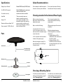
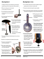
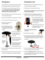
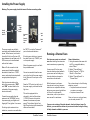
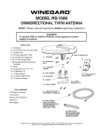
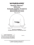
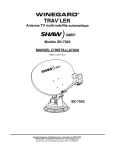
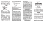
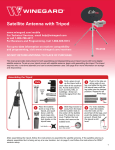
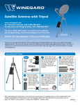
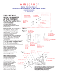
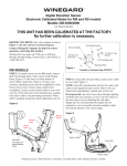
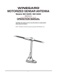
Omnidirectional TV/FM Antenna
For Technical Services,
email [email protected] or call 1-800-788-4417.
DO NOT RETURN ANTENNA TO PLACE OF PURCHASE.
DO NOT SNAP THE ANTENNA HEAD AND PEDESTAL
TOGETHER PRIOR TO READING MANUAL.
2452249
Specifications
Safety Recommendations
Range of up to 35 miles*
Models RS-3000 (white), RS-3035 (black)
For VHF & UHF channels
Models RP-RS30 (white) replacement
head and RP-RS35 (black)
replacement head are available.
For outdoor use only
Amplified
Height: 7.6”
Diameter of Antenna Head: 14.9”
Power required: 12 VDC at 85 mA
*Antenna reception may vary
based on transmitting antenna
tower height, lobe pattern of the
transmitter, height of the receiving
antenna, weather conditions, and
terrain on receiving path, including
trees, buildings and hills.
Do not attempt to install this system in
the rain or under any wet conditions.
Choosing a Location for the Antenna & Power Supply
Before mounting the antenna,
determine a location for the wall
plate/power supply.
Then, choose a location for the
antenna that meets the following
requirements:
Keep in mind the following:
Offers enough support for a secure
installation
A coaxial cable will have to run
from the the power supply to the
antenna and from the power supply
to each television.
Parts
A 12 V connection must be made to
the back of the power supply.
Refer to the diagram on page 7 for
more information on connecting to
the power supply.
Antenna head
Do not paint this antenna. Painting
the antenna will void your warranty.
Maintains adequate clearance
from the edge of the roof and any
obstructions
• clearance distance of 24 in.
needed from center of antenna to
front of the vehicle
• clearance distance of 18 in.
needed from center of antenna
to nearest obstruction and to the
edge of the roof
Front of Vehicle
Coax cable running
from antenna head
Mounting screw
18”
24”
18”
Obstruction
Top of Antenna
Scribe line
Rectangular gasket
Pedestal
Choosing a Mounting Option
Circular gasket
1
RoadStar Antenna
For cable entry directly beneath the
antenna, follow the steps on page 3
under “Mounting Option 1.”
RoadStar Antenna
For cable entry via a cable entry plate
(sold separately), follow the steps on
page 5 under “Mounting Option 2. “
2
Mounting Option 1
Mounting Option 1, Cont.
If installing the antenna so that the cable enters the vehicle directly
beneath the antenna, follow the steps below for Mounting Option 1.
12. Run a solid bead of sealant where the edge of the pedestal and gasket
assembly meets the roof and over the screw heads.
13. Gently push the cable slack downward through the pedestal.
1. Make sure the ceiling area is clear underneath
the chosen location for the antenna.
14. Twist the antenna head back and forth while pushing it onto the pedestal.
The pedestal should engage with the snap ring inside the antenna head.
2. Run coaxial cable from the chosen location for
the power supply to the chosen location for
the antenna.
3. Run the cable upward through the circular
gasket and pedestal.
Coaxial cable
running from
antenna head
Coaxial cable
running through
gasket and pedestal
Vertical groove
4. Connect the coaxial cable running
through the gasket and pedestal to
the coaxial cable running from the
antenna head.
Groove
7. Then, apply a liberal amount of sealant between the inner and outer
traced circles.
8. Replace the circular gasket where the sealant has been applied.
9. Plug the slot in the pedestal with the
provided rectangular gasket.
10. Before using the supplied screws,
check with the vehicle manufacturer
for any screw requirements.
11. Then, align the holes in the circular
gasket and pedestal. Mount the
assembly to the roof with four
screws, and tighten the four screws.
Rectangular
gasket
Pedestal
16. Push down again; you should hear
the head click into place.
Warning: Once the head and pedestal
are connected, the head cannot be
removed without incurring damage.
5. Place the circular gasket in the
chosen location for the antenna,
and trace around the inner and
outer edges of the gasket.
6. Check with the vehicle
manufacturer for approved sealant
for the vehicle.
3
Scribe line
15. While applying pressure, rotate the
head until feeling the grooves in
the head line up with the grooves
in the pedestal.
17. Check that the scribe line on the
pedestal is no longer visible. If the
scribe line is still visible, the head is
not fully seated on the pedestal.
18. Pull the antenna head upward. If
the head is unable to slide upward
on the pedestal, the head is fully
seated on the pedestal. If the head
slides upward, the head is not fully
seated on the pedestal.
19. If the antenna head is not fully
seated on the pedestal, repeat the
steps on this page to connect the
antenna head to the pedestal.
Do not proceed until the head is fully seated on the pedestal.
20. Once the head is fully seated on the pedestal, continue with “Installing the
Power Supply” on page 7. If the power supply is already installed, make
sure to run a channel scan after installing the antenna. See page 8 for
more information.
Slot
RoadStar Antenna
RoadStar Antenna
4
Mounting Option 2, Cont.
Mounting Option 2
If installing the antenna so that the cable enters the vehicle via a cable entry
plate (sold separately), follow the steps below for Mounting Option 2.
12. While applying pressure, rotate the head until feeling the grooves in the
head line up with the grooves in the pedestal.
1. Run coaxial cable from the power supply to the antenna via the cable
entry plate. The antenna needs to be at least 8 inches from the cable
entry plate. Do not fasten the coaxial cable at this point because
additional coaxial cable is required later (see step 18).
13. Push down again; you should hear the head click into place.
2. Place the circular gasket in the chosen location for the antenna, and trace
around the outer edge of the gasket.
14. Check that the scribe line on the pedestal is no longer visible. If the
scribe line is still visible, the head is not fully seated on the pedestal.
Warning: Once the head and pedestal are connected, the head cannot be
removed without incurring damage.
3. Check with the vehicle manufacturer for approved sealant for the vehicle.
15. Pull the antenna head upward. If the head
is unable to slide upward on the pedestal,
the head is fully seated on the pedestal. If
the head slides upward, the head is not fully
seated on the pedestal.
4. Then, apply a liberal amount of sealant in the traced circle.
5. Replace the circular gasket where the
sealant has been applied.
6. Run the coaxial cable upward through
the antenna pedestal. Make sure the cable
runs through the slot on the underside of
the pedestal.
Coaxial cable
running from
antenna head
Coaxial cable
running through
pedestal
16. If the antenna head is not fully seated on the
pedestal, repeat the steps to connect the
antenna head to the pedestal.
Slot
7. Connect the coaxial cable running
through the pedestal to the
coaxial cable running from the
antenna head.
8. Before using the supplied screws,
check with the vehicle manufacturer
for any screw requirements.
Do not proceed until the head is fully seated
on the pedestal.
17. Pull the cable away from the antenna.
18. At a point 4” from the antenna along the excess cable, create a loop of
5” diameter between the antenna and entry plate. Clamp at the top of the
loop, at 8” linear distance from the antenna, and every 12–16” thereon
along the cable.
9. Then, align the holes in the circular
gasket and pedestal. Mount the
assembly to the roof with four
screws, and tighten the four screws.
5 in
8 in
10. Gently push the cable slack downward through the pedestal, and pull the
cable through the slot.
19. Run a solid bead of sealant where the edge of the pedestal meets the roof,
over the screw heads and around the slot in the pedestal.
11. Twist the antenna head back and forth while pushing it onto the pedestal.
The pedestal should engage with the snap ring inside the antenna head.
20. Continue with “Installing the Power Supply” on page 7. If the power
supply is already installed, make sure to run a channel scan after installing
the antenna. See page 8 for more information.
5
RoadStar Antenna
RoadStar Antenna
6
Installing the Power Supply
Warning: The power supply should be turned off when connecting cables.
Indicator
light
Coaxial
port for
main TV
On/Off
button
The power supply may be flush
mounted in most standard electrical
boxes. To flush mount, cut a hole in
the wall to fit the box. Run two #12
wires between the wall plate and +12
VDC source, and route downlead
cable to this location.
Make a 12 volt connection to the
power supply. Install the supplied
terminals on wires from +12 VDC
source, and crimp the terminals with
an appropriate crimping tool.
Push the wires onto tabs on the
back of the power supply. (“PWR”
and “GND” are also noted on the
underside of the power supply
electronics board.)
Connect the coax cable from the
antenna to the “ANTENNA” port on
the power supply, and tighten until
fingertight. Then, tighten ¼ turn more.
If hooking up the antenna to two
televisions, connect a coax cable from
7
Antenna
port
Set 2
port
Power &
Ground
tabs
Cable
port
the “SET 2” port to the “Antenna In”
port on the second television.
If hooking up a cable input, connect
the cable input to the “CABLE” port
on the power supply.
Mount the power supply in wall with
the provided screws.
Connect a coax cable from the coax
port on the front of the power supply
to the “Antenna In” coax port on the
main TV.
Press the “ON” switch on the front of
the power supply, and check that the
light is on.
This unit is equipped with a
polyswitch, which will shut down
+12 VDC if there is a direct short
between the antenna and power
supply. The indicator light will not
light. Once the short is eliminated, the
device will reset itself.
RoadStar Antenna
Running a Channel Scan
First time users must run a channel
scan after installing the antenna to
receive maximum programming.
A new scan will find any new
channels that have been added in
your area as well as finding any
channels that have changed or
moved since the last scan.
While the steps to perform a
channel scan may vary between
televisions or compatible devices,
below are some general guidelines
to follow. For more specific
instructions, refer to your device
user manual for assistance.
General Instructions
1. Using the remote that came with
the TV or compatible device,
select “Menu.”
2. Select “Channel Setup.”
3. Select “Antenna” or “Off-Air
Mode” or “Auto-Scan.”
4. Select “Channel Search” or
“Channel Scan.”
Run a channel scan in the following
situations, as well:
• Anytime the antenna is moved
or enters a new region
• Anytime a channel is lost
Once you have run a channel scan,
you are ready to watch TV.
If you are not receiving all desired channels, check out dtv.gov/maps. On
this site, you can enter the address of your current location and get a listing
of likely channels available in your area.
RoadStar Antenna
8
Troubleshooting
Do not install couplers, splitters, etc.
between the power supply and the
antenna. Installation of any item on
the downlead may cause a short in the
system. The downlead supplies +12
VDC to the preamp in the antenna.
WINEGARD MOBILE PRODUCTS LIMITED WARRANTY
(2 YEARS PARTS; 1 YEAR LABOR)
The power supply should be turned
OFF when connecting/disconnecting
cables to power supply and antenna
but should be turned ON when
testing for voltage.
Testing Power Supply
Make sure the TV set is
working properly.
Remove the power supply from
wall, and visually inspect for
burned/broken parts. If there are
ANY broken/burned parts, replace
power supply.
Disconnect the cable from the
antenna jack on the power supply.
Check for +12 VDC. If +12 VDC is
present, there is a cable problem
connecting the power supply to the
antenna. Repair/replace cable.
If +12 VDC is not present at the
antenna jack, be sure the indicator
light is ON. If not, check the polarity
of the red/white wires and the +12
VDC source.
For Technical Services,
email [email protected] or call 1-800-788-4417.
Winegard Company warrants this product against defects in materials or workmanship for a
period of two (2) years from the date of original purchase. During year one (1) of such warranty,
Winegard Company will also pay authorized labor costs to an authorized Winegard dealer to
repair or replace defective products. No warranty claim will be honored unless at the time the
claim is made, Customer presents proof of purchase to an authorized Winegard dealer (to locate
the nearest authorized Winegard dealer, contact Winegard Company, 3000 Kirkwood Street,
Burlington, Iowa 52601, Telephone 800-288-8094 or visit www.winegard.com). Customer must
provide proof of purchase with a dated sales receipt for the Winegard product to verify the
product is under warranty. If the date of purchase cannot be verified, the warranty period shall
be considered to begin thirty (30) days after the date of manufacture.
If a defect in material or workmanship is discovered, Customer may take the product to an
authorized Winegard dealer for service. Customer must provide proof of purchase to verify
the product is under warranty. If the product is brought to an authorized Winegard dealer
for service prior to expiration of year one (1) of the warranty period and a defect in material
or workmanship is verified by Winegard Technical Services, Winegard Company will cover
the Winegard dealer’s labor charges for warranty service. The Winegard dealer must contact
Winegard Technical Services in advance for pre-approval of the service. Approval of the service
is at the sole discretion of Winegard Company.
Alternatively, Customer may ship the product prepaid to Winegard Technical Services
(located at 3111 Kirkwood Street, Burlington, Iowa 52601, Telephone 800-788-4417). Customer
must return the product along with a brief description of the problem and provide Winegard
Technical Services with Customer’s name, address, and phone number. Customer must also
provide proof of purchase to verify the product is under warranty. If the product is returned
before the expiration of the warranty period, Winegard Company will (at its option) either repair
or replace the product.
This Limited Warranty does not apply if the product has been damaged, deteriorates,
malfunctions or fails from: improper installation, misuse, abuse, neglect, accident, tampering,
modification of the product as originally manufactured by Winegard in any manner whatsoever,
removing or defacing any serial number, usage not in accordance with product instructions or
acts of nature such as damage caused by wind, lightning, ice or corrosive environments such
as salt spray and acid rain. This Limited Warranty also does not apply if the product becomes
unable to perform its’ intended function in any way as a result of the television signal provider
making any changes in technology or service.
RETURN AUTHORIZATION POLICY
A Return Material Authorization (RMA) is required prior to returning any product to Winegard
Company or Winegard Warranty Services under this warranty policy. Please call our Technical
Services Department at 800-788-4417 or send an e-mail to [email protected] to obtain the
RMA number. Please furnish the date of purchase when requesting an RMA number. Enclose the
product in a prepaid package and write the RMA number in large, clear letters on the outside of
the package. To avoid confusion or misunderstanding, a shipment(s) without an RMA number(s)
or an unauthorized return(s) will be refused and returned to Customer freight collect.
WINEGARD COMPANY DOES NOT ASSUME ANY LIABILITIES FOR ANY OTHER WARRANTIES,
EXPRESS OR IMPLIED, MADE BY ANY OTHER PERSON.
ALL OTHER WARRANTIES WHETHER EXPRESS, IMPLIED OR STATUTORY INCLUDING
WARRANTIES OF FITNESS FOR A PARTICULAR PURPOSE AND MERCHANTABILITY ARE
LIMITED TO THE TWO YEAR PERIOD OF THIS WARRANTY.
In states that do not allow limitations on implied warranties, or the exclusion of limitation of
incidental or consequential damages, the above limitations or exclusions do not apply.
Some states do not allow limitations on how long an implied warranty lasts, or the exclusion
of limitation of incidental or consequential damages, so the above limitations or exclusions
may not apply to you.
This warranty gives Customer specific legal rights. Customer may also have other rights that
may vary from state to state
SATELLITE RECEIVER WARRANTY
See manufacturer’s limited warranty policy.
9
RoadStar Antenna
WS-MOBWARREV2
Rev. 1/10
Winegard Company • 3000 Kirkwood Street • Burlington, IA 52601
800-288-8094 • Fax 319-754-0787 • www.winegard.com • Printed in U.S.A.
©2011 Winegard Company Rev4 7/12 2452249
Winegard is a registered trademark of Winegard Company, and RoadStar is a trademark of Winegard Company.
dtv.gov is not affiliated with Winegard Company.
Disclaimer: Although every effort has been made to ensure that the information in this manual is correct and
complete, no company shall be held liable for any errors or omissions in this manual. Information provided in
this manual was accurate at time of printing.