1
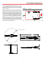
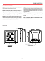
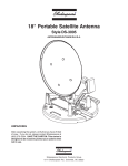
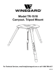
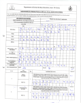
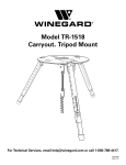
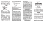
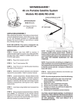
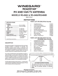
®
WINEGARD
MOTORIZED SENSAR ANTENNA
®
Models MA1055W & MA1055G
MADE IN U.S.A.
U.S. Patents D500,496 and 7,358,909
INSTALLATION MANUAL
CAUTION: This system is not for use with antenna in raised position
while vehicle is in motion.
OEM Model MA1055W has white antenna head and white turret.
OEM Model MA1055G has gray antenna head and black turret.
Unit packed as follows:
Motorized Mount with booms attached.
Antenna Head
Hardware Bag
Instructions
Power Cable (Sold separately, CL-MA03)
Control Cable (Sold separately, CL-MA06)
Control Panel (Sold separately, MA-CP4W (White), MA-CP4B (Black))
Read Installation Instructions before installing unit.
Read Motorized Sensar Operation before operating unit.
1
Tools Needed/Specifications
Tools needed for installation
Tape measure
7/16" wrench
Cutter
5/16" socket/nut driver
Phillips screwdriver
1-1/2" to 3" hole saw (cable entry hole)
Electric or cordless drill
Sealant compatible with roof material (check with your
vehicle manufacturer for compatibility)
1/8" drill bit (for pilot holes)
System Specs for Motorized Sensar
Electronic Specifications:
Operating Voltage Nominal 12VDC - Operating range 9.5 VDC to 15.5 VDC
Current draw of electronics when Power Light is off — Nominal 500uA, 1.5mA Max.
Current draw of electronics when Power Light is on — Nominal 46mA, 70mA Max.
Current draw of electronics when Power Light is on and motor running — 3 amp Max.
Control Panel Size: 4.5 x 4.5 x
Control Panel Weight: .5 lbs.
Warning Device – .2 amps (not included)
Mount Specifications:
General Specifications:
Height Lowered: 5-1/2"
Operating Temperature: -10 to +130F
Height Raised: 33-1/2"
Humidity 90% noncondensing
Roof Space Required: 13.5 x 66" (Stowed position)
Shipping Weight OEM Models: 18.25 lbs.
Turning Diameter: 52"
Carton Size: 48" x 12" x 10-3/4"
Weight of Mount: 11.25 lbs.
Rev. 8/06
2
Pre-Installation Requirements
To install the Winegard Motorized Sensar antenna, check
with your RV dealer or manufacturer. Your RV may already
be pre-wired for this system, and/or may have a reinforced
roof area available.
FIGURE 3
Roof Edge
c 10 inches
STEP 1: Choose location for antenna system on roof area.
Figure 3 illustrates placement of system, showing it in travel
position. You must be able to raise and rotate antenna
without interfering with other roof-mounted equipment. When
selecting location, keep in mind how you will route the cables
to and from mount. Beware of any obstacles in roof area
that may interfere with or be damaged during installation.
d Min.
FRONT
OF RV
e
f
2 Feet
Min.
STEP 2: Choose location inside RV for mounting control
panel. It is recommended that the control panel be in viewing
area of most watched TV so you can see TV picture to turn
antenna to best picture reception for your area. A 12VDC
power source must also be available.
e 2 Feetf
Min.
c 10 inches
d Min.
Ø 52" Raised Operating Diameter
66"
13.5"
33.5" Raised Height
5.5
3
Roof Installation
STEP 1: Attach antenna head to booms shown in Figure 2
using two pins and E-Clips found in hardware package.
Fasten coax to antenna head. See Figure 2B.Tighten coax
connection per instruction decal on antenna head.
STEP 3: In traced triangular area for cables, drill a hole (1.5"
to 3" Dia.) in roof. Route cables through roof to where you have
selected control panel to be mounted. See Figure 4.
FIGURE 4
Drill hole 1-1/2" to 3"
Diameter for Wires on Roof
Leveling Bracket
FIGURE 2
Antenna
Head
c
(2) E-Clips
(2) Steel Pins
STEP 4: Place antenna system on your previously selected
traced location, and fasten in place with mounting screws.
Depending on roof construction you may need to drill pilot holes
for mounting screws. See Figure 5.
Lift Tubes
FIGURE 2B
FIGURE 5
Coax
Connector
Cable
Connector
c
c
c
c
Don't get
Sealant on
Painted
Turret Top
Mounting
Screws
c
STEP 2: Remove the three screws holding triangle-shaped
cover with WINEGARD on it from antenna base. You will see
a coax cable and control cable (approx. 6" long). With antenna
system positioned on roof trace the outline of the mount and
also trace the inside wall outline of cable area. Set mount off to
the side of the traced area. (See figures 3 & 4).
O-Ring
STEP 5: Make cable connections from wires on the roof, to
wires in mount. Apply approved sealant around cable entry
hole. Replace cover over cable area making sure O-Ring is in
place. Then tighten the three cover screws. See Figure 5.
FIGURE 3
Screws
STEP 6: After antenna is secured to roof, apply approved
sealant around edge of mount and over screw heads. NOTE:
Consult RV manufacturer for approved sealant.
4
Inside Installation
Control Panel Installation
STEP 1: Run control cable from roof mount to control panel.
Do not connect to control panel at this time.
STEP 4: Control panel can be mounted directly to surface
providing surface has sufficient space behind panel for wiring.
Should you be limited to space behind panel or choose not to
have wires concealed behind control panel, you can use the
surface mount box.
STEP 2: Connect power cable to a fused 12VDC source. It is
recommended that the power source is separate from other
appliances, to avoid possible electrical interference. Do not
connect wire to control panel at this time. Note: Orange wire
supplied for optional "Antenna Up" warning. DO NOT
connect it to a 12VDC power source.
STEP 5: After prepping area to mount control panel, test fitting
to make sure it fits in location correctly, and connect control
cable and power wires to panel. Then secure panel to it's
location.
STEP 3: Run coax cable from roof mount to power source for
antenna head preamplifier. Power source may be a powered
12VDC video switch or wall plate power supply. Connect a
second coax cable from power source to television.
Refer to Operations Manual for instructions to raise,
lower, and rotate antenna.
Control Panel
.625
.875
3.280
3.674
4.485
4.564
POWER CABLE CONNECTION
CONTROL CABLE CONNECTION
NOTE: SHOWN WITHOUT
SURFACE MOUNT BOX.
5
Warranty
Returned units damaged in shipping due to improper packing will be charged to the dealer/customer.
WINEGARD MOBILE PRODUCTS LIMITED WARRANTY
(2 YEARS PARTS; 1 YEAR LABOR)
Winegard Company warrants this product against defects in materials or workmanship for a period of two (2) years from the date
of original purchase. During year one (1) of such warranty, Winegard Company will also pay authorized labor costs to an authorized
Winegard dealer to repair or replace defective products. No warranty claim will be honored unless at the time the claim is made,
Customer presents proof of purchase to an authorized Winegard dealer (to locate the nearest authorized Winegard dealer, contact
Winegard Company, 3000 Kirkwood Street, Burlington, Iowa 52601, Telephone 800-288-8094 or visit www.winegard.com).
Customer must provide proof of purchase with a dated sales receipt for the Winegard product to verify the product is under warranty.
If the date of purchase cannot be verified, the warranty period shall be considered to begin thirty (30) days after the date of
manufacture.
If a defect in material or workmanship is discovered, Customer may take the product to an authorized Winegard dealer for service.
Customer must provide proof of purchase to verify the product is under warranty. If the product is brought to an authorized Winegard
dealer for service prior to expiration of year one (1) of the warranty period and a defect in material or workmanship is verified by
Winegard Technical Services, Winegard Company will cover the Winegard dealer’s labor charges for warranty service. The
Winegard dealer must contact Winegard Technical Services in advance for pre-approval of the service. Approval of the service
is at the sole discretion of Winegard Company.
Alternatively, Customer may ship the product prepaid to Winegard Technical Services (located at 3111 Kirkwood Street, Burlington,
Iowa 52601, Telephone 800-788-4417). Customer must return the product along with a brief description of the problem and provide
Winegard Technical Services with Customer’s name, address, and phone number. Customer must also provide proof of purchase
to verify the product is under warranty. If the product is returned before the expiration of the warranty period, Winegard Company
will (at its option) either repair or replace the product.
This Limited Warranty does not apply if the product has been damaged, deteriorates, malfunctions or fails from: improper installation,
misuse, abuse, neglect, accident, tampering, modification of the product as originally manufactured by Winegard in any manner
whatsoever, removing or defacing any serial number, usage not in accordance with product instructions or acts of nature such
as damage caused by wind, lightning, ice or corrosive environments such as salt spray and acid rain. This Limited Warranty also
does not apply if the product becomes unable to perform its’ intended function in any way as a result of the television signal provider
making any changes in technology or service.
RETURN AUTHORIZATION POLICY
A Return Material Authorization (RMA) is required prior to returning any product to Winegard Company or Winegard Warranty
Services under this warranty policy. Please call our Technical Services Department at 800-788-4417 or send an e-mail to
[email protected] to obtain the RMA number. Please furnish the date of purchase when requesting an RMA number.
Enclose the product in a prepaid package and write the RMA number in large, clear letters on the outside of the package. To avoid
confusion or misunderstanding, a shipment(s) without an RMA number(s) or an unauthorized return(s) will be refused and returned
to Customer freight collect.
WINEGARD COMPANY DOES NOT ASSUME ANY LIABILITIES FOR ANY OTHER WARRANTIES, EXPRESS OR IMPLIED,
MADE BY ANY OTHER PERSON.
ALL OTHER WARRANTIES WHETHER EXPRESS, IMPLIED OR STATUTORY INCLUDING WARRANTIES OF FITNESS
FOR A PARTICULAR PURPOSE AND MERCHANTABILITY ARE LIMITED TO THE TWO YEAR PERIOD OF THIS
WARRANTY.
In states that do not allow limitations on implied warranties, or the exclusion of limitation of incidental or consequential damages,
the above limitations or exclusions do not apply.
Some states do not allow limitations on how long an implied warranty lasts, or the exclusion of limitation of incidental or consequential
damages, so the above limitations or exclusions may not apply to you.
This warranty gives Customer specific legal rights. Customer may also have other rights that may vary from state to state
SATELLITE RECEIVER WARRANTY
See manufacturer’s limited warranty policy.
6
WS-MOBWARREV2
Rev. 1/10
Notes
7
Printed in U.S.A. Winegard Company • 3000 Kirkwood Street • Burlington, Iowa 52601-2000 © Winegard Company, 2006 2452068 Rev.3 8/10
8