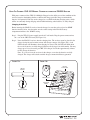
1
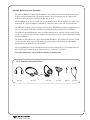
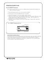
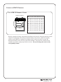
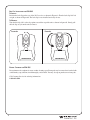
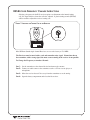
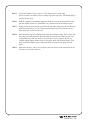
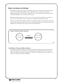
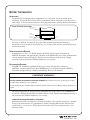
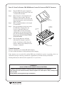
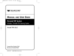
®
MANUAL
AND
USER GUIDE
HEARING HELPER™ Tour Guide System
Wireless, Portable FM Listening System
Model TGS PRO 720
Transmitter Model PFM T31
Receiver Model PPA R35
MAN 122A
HEARING HELPER™ FM TOUR GUIDE SYSTEM, MODEL TGS PRO 720
INSTALLATION GUIDE & USER MANUAL
Contents
Page
SYSTEM OVERVIEW
3
SYSTEM COMPONENTS
4
PFM T31 TRANSMITTER
MICROPHONES
PPA R35 RECEIVER
HEADPHONES & EARPHONES
SAFETY INFORMATION
6
RECYCLING INSTRUCTIONS
6
OPERATING INSTRUCTIONS
7
PFM T31 TRANSMITTER
PPA R35 RECEIVER
HINTS FOR USING THE SYSTEM
BATTERY INFORMATION
14
BATTERY INSTALLATION
RECHARGEABLE & NON-RECHARGEABLE BATTERIES
USING OPTIONAL BATTERY CHARGERS
2
IN CASE OF DIFFICULTY
17
WARRANTY
18
SYSTEM SPECIFICATIONS
19
®
SYSTEM OVERVIEW
The HEARING HELPER™ Tour Guide System is a portable, high-performance, wireless system
composed of the PFM T31 Transmitter and PPA R35 Receivers and designed for use in guided tour
applications. The system allows one-way transmission of a tour guide’s voice to group members
using an FM radio signal. Using the system helps group members overcome background noise and
distance from the person speaking.
The HEARING HELPER™ System can be used for large or small tour groups and in noisy or quiet
environments.
Your HEARING HELPER™ Tour Guide System has two principal parts: the transmitter and the
receiver. Much like a miniature radio station, the transmitter and microphone pick up the sounds you
want to hear and broadcast them over an FM radio signal. The receivers and headphones are used to
pick up the broadcast up to 100 meters away.
To avoid difficulties, please read through these instructions as you begin to use the system. Then save
them for questions that arise as you continue to use your system.
FIGURE 1:
HOW THE TOUR GUIDE SYSTEM WORKS
FM Radio Signal
Tour Guide Uses the Body Pack
Transmitter With Microphone
Listeners use Personal Receivers with
Headphones, Earphones, Or Neckloop
The tour guide wears the body-pack transmitter and headset microphone. The guide’s
voice is broadcast as an FM radio signal over a distance of up to 100 meters. Listeners use
the pocket receiver and headphone to hear the speaker’s voice directly, with reduced
background noise. A neckloop telecoil coupler allows the system to be used with telecoil
(T-Switch) equipped hearing aids, at somewhat reduced range.
If you have problems with the HEARING HELPER™ Tour Guide System, don’t hesitate to call
Williams Sound at 1-800-328-6190.
®
3
SYSTEM COMPONENTS
þ
Body Pack Transmitter (PFM T31) with (2) AA batteries (BAT 001)
þ
Noise-cancelling headband microphone (MIC 086)
þ
(6) Receivers (PPA R35) w/batteries (BAT 001)
þ
Instruction Manual (MAN 122)
þ
System carry case (CCS 030 S)
THE PFM T31 TRANSMITTER
The PFM T31 Transmitter is a battery-powered body-pack model used with a microphone to pick up
the tour guide's voice. The transmitter produces an FM radio signal to broadcast the tour guide's
voice to the receiver units. A simple slide switch on top of the transmitter turns the unit on or off.
The PPA T31 operates on two AA non-rechargeable alkaline batteries (BAT 001), or two AA
rechargeable NiMH batteries (BAT 026).
MICROPHONES
A noise-cancelling, headband microphone (MIC 086) is the standard microphone. The noisecancelling microphone helps to reduce background sounds in noisy environments. The microphone
plugs into the “MIC” jack on top of the Transmitter. The microphone should be positioned directly
in front of the tour guide's mouth to achieve an optimal signal to noise ratio and so that head
movement does not affect the loudness of the signal. The microphone cord acts as the transmitting
antenna.
Optional Microphones
An optional Hearing Protector Headset Microphone (MIC 036) is also available for extremely high
noise environments. It features ear muffs that completely cover both ears and provides 24 dB noise
isolation for hearing protection.
An optional Lapel Clip Microphone can be used in quieter environments like museums or galleries.
The MIC 090 has an omnidirectional pick-up pattern. The MIC 056 has a directional (or cardioid)
pick-up pattern, which will reduce background noise somewhat.
A directional hand-held microphone (MIC 027) is also available for tour guides who prefer to hold
the microphone.
THE PPA R35 RECEIVER
The PPA R35 Receiver is a battery-powered body-pack receiver used with a headphone to hear the
signal produced by the transmitter. The receiver is pre-tuned to the transmitter and has a useradjustable volume on/off control, LED power and low battery indicator. The headphone plugs into
the “EAR” jack on top of the Receiver. The PPA R35 Receiver operates on two AA nonrechargeable alkaline batteries (BAT 001), or two AA rechargeable NiMH batteries (BAT 026).
4
®
OPTIONAL HEADPHONES AND EARPHONES
The optional HED 021 Lightweight Headphone is the standard headset for the Tour Guide System.
It offers excellent sound quality and wearing comfort. The foam earpads may be removed and
washed in a mild detergent, rinsed thoroughly, and air dried.
The headphone plugs into the “EAR” jack on top of the Receiver. The headphones are wired with a
mono plug. If a stereo headphone is substituted, it will only work on one side of the headphone.
The HED 008 is a heavy-duty, hearing-protector headset. The HED 008 earmuffs completely cover
the ears and provide 24 dB noise isolation for hearing protection in high noise environments.
The EAR 022 Surround Earphone offers excellent sound quality in a unique style that hangs on the
ear. It is easy to keep clean since the earphone does not enter the ear. It is not recommended for high
noise environments.
The EAR 013 and EAR 014 are single and dual Mini Earphones. The earbud-style features a foam
covering that fits in the outer ear. The foam pads can be removed for cleaning or replacement.
Replacement pads (EAR 015-10) are available.
The stylish HED 026 rear-wear headphone offers excellent sound quality; it rests comfortably over
the ears and wraps around the back of the head for a less obtrusive, relaxed fit.
For order information, contact Williams Sound at 1-800-843-3544.
FIG. 2: EARPHONE / HEADPHONE OPTIONS
R
HED 008
HED 021
®
HED 026
EAR 022
EAR 013
EAR 014
5
SAFETY INFORMATION
HEARING SAFETY
CAUTION!
This product is designed to amplify sounds to a high volume level which could
potentially cause hearing damage if used improperly. To protect your hearing and the
hearing of others:
1. Make sure the volume is turned down before putting on the earphone or headphone.
Then adjust the volume to a comfortable level.
2. Set the volume level at the minimum setting that you need to hear.
3. If you experience feedback (a squealing or howling sound), reduce the volume
setting and move the microphone away from the earphone or headphone.
4. Do not allow children or other unauthorized persons access to this product.
BATTERY SAFETY AND DISPOSAL
CAUTION!
This product is supplied with disposable Alkaline batteries. Do not attempt to recharge
disposable batteries, which may explode, release dangerous chemicals, cause burns or
other serious harm to the user or product.
PACEMAKER SAFETY:
CAUTION!
1.
Before using this product with a pacemaker or other medical device, consult your
physician or the manufacturer of your pacemaker or other medical device.
2.
If you have a pacemaker or other medical device, make sure that you are using this
product in accordance with safety guidelines established by your physician or the
pacemaker manufacturer.
RECYCLING INSTRUCTIONS
BATTERY SAFETY AND DISPOSAL
Help Williams Sound protect the environment! Please take the time to dispose of
your equipment properly.
Product Recycling for Customers in the European Union:
Please do NOT dispose of your Williams Sound equipment in the household trash.
Please take the equipment to a electronics recycling center; OR return the product to
the factory for proper disposal.
Battery Recycling for Customers in the European Union:
Please do NOT dispose of used batteries in the household trash. Please take the
batteries to a retail or community collection point for recycling.
3/28/06
6
®
OPERATING INSTRUCTIONS
USING THE PFM T31 TRANSMITTER
Note: Before you begin, make sure you have AA Alkaline batteries installed in the transmitter. See
Battery Information on page 14.
1. Plug the microphone into the “mic” jack on top of the transmitter.
2. Turn the power on: Place the FM switch to the “On” position.
3. Position the microphone as close to the speaker’s mouth as practical.
4. When you are ready to speak, turn the Mic Mute Switch to the “On” position. When you are done
speaking, mute the mic by turning the switch to the “Off” position. This will eliminate any
unwanted noise as a result of the transmitter being on.
5. Remember to turn the transmitter off when you are done using it: Turn the “FM” switch to the
“Off” position.
FIG. 3: PFM T31 TRANSMITTER TOP VIEW
On/Off Switch
Off
Mic
On
FM
Mic
Williams Sound FM
Mic Jack
Mic Mute Switch
Note On The Transmitter Antenna:
The microphone cord is the transmitting antenna. Do not bunch up the cord, wrap it tightly around your
body, or wrap it around the transmitter. For maximum range, the cord should hang as straight as
possible. The transmitter can be placed in a pants pocket, or clipped onto a belt or waistband. Make
sure the transmitter is turned OFF when not in use.
®
7
CHANGING THE PFM T31 FREQUENCY
FIG. 4: PFM T31 FREQUENCY CHANGE
Frequency Switches
Switch Settings
MHz
1
2
3
4
5
6
7
8
72.1
72.3
72.5
72.6
72.7
72.8
72.9
74.7
75.3
75.4
75.5
75.7
75.9
DN
DN
DN
DN
DN
DN
DN
UP
UP
UP
UP
UP
UP
UP
UP
UP
DN
UP
UP
UP
DN
UP
UP
UP
UP
UP
DN
DN
DN
UP
DN
DN
DN
DN
DN
DN
DN
DN
DN
UP
UP
UP
DN
UP
DN
UP
UP
UP
DN
UP
UP
UP
DN
UP
DN
DN
UP
DN
DN
UP
DN
UP
UP
DN
UP
DN
DN
DN
DN
DN
DN
DN
DN
DN
DN
DN
DN
DN
DN
DN
UP
DN
UP
DN
DN
DN
DN
DN
DN
UP
UP
DN
DN
DN
UP
DN
UP
UP
UP
DN
DN
DN
DN
DN
Switches set for 72.9 MHz
1 2 3 4 5 6 7 8
UP (OFF) DOWN (ON)
Battery
Compartment
Begin by opening the battery compartment door. Remove the batteries, then open the back panel to
expose the circuit board. Referencing the Switch Settings chart (above), adjust the frequency
switches on the PFM T31 transmitter accordingly using a small screw driver or paper clip.
Reinstall the batteries, then close the back of the transmitter. Plug in the mic, and turn on the
transmitter to provide a tuning signal for the receivers. Be sure to change the receiver to the
corresponding channel.
8
®
USING THE PPA R35 RECEIVER
Note: Rechargeable batteries are shipped in a discharged state and must be charged overnight
before using.
1. Make sure there are two charged AA batteries in the Receiver. If batteries are not installed, see
Battery Information on page 14.
NOTE: The ON indicator will illuminate RED to indicate low battery.
2. Plug the earphone or headphone into the “Ear” jack on top of the Receiver.
FIG. 5: PPA R35 RECEIVER TOP VIEW
On/Off
Volume Switch
Earphone
Jack
3. Place the headphones over your ears.
"On" Indicator
LED
R35 Top
4. Turn the receiver on by rotating the volume control knob clockwise. The receiver’s ON
indicator should illuminate green.
5. Adjust the receiver volume control to a comfortable listening level.
You should be able to hear someone speaking into the transmitter microphone.
R35 Front
®
9
BELT CLIP INSTALLATION FOR PPA R35
TO INSTALL:
Position the belt clip on the rear of the R-35 receiver as shown in Figure 6a. Turn the belt clip 180º left
or right as shown in Figure 6b. The belt clip is now installed and ready for use.
TO REMOVE:
Turn the belt clip 180º so the edge points toward the top of the unit as shown in figure 6b. Gently pull
the belt clip away from the unit to remove.
FIGURE 6A
FIGURE 6B
– or –
EARPAD CLEANING FOR PPA R35
Do not immerse the earphone in water or other cleaning agent. Foam pads may be removed and washed with
a mild laundry soap solution, rinsed thoroughly, and air dried. You may also opt to purchase new foam pads.
Call Customer Service for ordering information:
1-800-843-3544
10
®
R35 RECEIVER FREQUENCY CHANGE INSTRUCTIONS
Selecting a frequency for the R35 receiver requires an adjustment to the internal tuning
coil. See figure below to locate the coil to be adjusted. A plastic tuning wrench (PLT 005)
will be needed to adjust this receiver’s tuning coil.
FIGURE 7: LOCATING THE TUNING COIL IN THE RECEIVER
TUNING COIL
Ferrite Tuning
"Slug"
Alkaline
NiMH
Channel Tuning
R-35
Most Williams Sound single channel Receivers are set at the factory to 72.9 MHz.
The Receiver must be tuned with a weak and somewhat noisy signal. If tuned too close to
the transmitter, with a strong signal, the most accurate tuning of the receiver is not possible.
To Change the Frequency to Another Channel:
STEP 1: Set the transmitter to the channel desired and remove the antenna.
STEP 2: Connect an audio source to the transmitter such as a CD or cassette player or
microphone.
STEP 3: Move the receiver about 25 feet away from the transmitter to set the tuning.
STEP 4: Open the battery compartment on the back of the receiver.
®
11
12
STEP 5:
Locate the Tuning Coil (see figure 7). The tuning coil is a small. shiny
metal can with a screwdriver slot in a tuning slug in the top center. The Tuning Slug is
usually black or gray.
STEP 6:
With the earphone or headphone supplied with the receiver plugged into the Ear Jack,
turn the volume control to a comfortable level, and listen for the transmitted signal.
STEP 7:
Gently put the tip of the tuning wrench into the slot in the tuning slug. Be careful not to
push hard on the slug so as not to damage the threads in the coil, and do not screw it
down more than 3 turns into the coil.
STEP 8:
Turn the tuning slug in a counterclockwise direction about two turns. Then, slowly turn
the tuning slug in the clockwise direction until the signal is heard. There may be two
signal points heard. The one which is received first is a false response. Be sure to
continue tuning slightly further to the correct point, which will be much louder. Tune
back and forth to find the center of the point of best response to the program being
heard.
STEP 9:
Mark down the date, and if a new frequency has been chosen, mark it down inside the
receiver case for future reference.
®
HINTS FOR USING THE SYSTEM
Normal operating distance between the transmitter and receiver is about 30 meters. The operating
range will vary in different buildings and surroundings. In some locations, the signal may
momentarily disappear. This is called a “drop-out” and is due to reflection and cancellation of the
radio signal. Moving a few feet will restore the signal.
Keep the transmitter and receiver units at least a meter apart. If the transmitter gets too close to a
receiver, it can overload the receiver, causing noisy reception or blocking of the signal.
Do not use more than one transmitter on the same channel (frequency) at the same time unless they
are physically separated by more than 30 meters. Operating more than one transmitter on the same
channel at the same time in the same place will result in interference.
FIGURE 8: TOUR GUIDE GROUP SEPARATION
Tour Group 1
30 Meters
Channel A
Tour Group 2
Channel A
USING MULTIPLE SYSTEMS FOR MULTIPLE GROUPS:
For multiple tour groups within the same facility, multiple Tour Guide Systems may be operated
on the same channel at the same time by maintaining physical separation of 30 meters between
groups. The physical separation of groups takes advantage of the FM capture effect which causes
receivers to lock onto the closest transmitter.
®
13
BATTERY INFORMATION
INSTALLATION
To open the T31 transmitter battery compartment, use a coin in the slot on the bottom of the
transmitter. To open the R35 receiver battery compartment, lift the tab on the back of the receiver
with a finger. Press the batteries into place, observing proper battery polarity. Incorrect insertion of
FIGURE 9: BATTERY INSTALLATION
Rear of Transmitter
or Receiver
Battery
Compartment
Note Proper
Polarity
–
+
+
–
Tab
the battery is difficult, and if forced, may cause both mechanical and electrical damage to
transmitters or receivers not covered by the five year warranty. Units will not work with the battery
incorrectly installed.
NON-RECHARGEABLE BATTERIES
In normal use, two AA 1.5 V alkaline batteries (BAT 001) will last about 12 hours in the
PFM T31 Transmitter and approximately 100 hours in the PPA R35 Receiver. If the sound becomes
weak or distorted, replace the batteries. Do not leave dead batteries in the receivers. Battery
corrosion is not covered by the Williams Sound five year warranty.
RECHARGEABLE BATTERIES
The PFM T31 Transmitter and PPA R35 Receivers can use rechargeable AA batteries
(BAT 026). On an overnight charge, these NiMH batteries are designed to operate a PFM T31
Transmitter for approximately 10 hours, and PPA R35 Receivers for 56 hours.
!! IMPORTANT WARNINGS !!
DO NOT ATTEMPT TO RECHARGE ZINC CARBON (“HEAVY DUTY”), ALKALINE, OR LITHIUM BATTERIES!
DO NOT ATTEMPT TO RECHARGE DISPOSABLE BATTERIES! These batteries may heat up and explode, causing
possible injury and damage to the equipment.
Avoid shorting the plus and minus battery terminals together with metal objects. Battery damage and burns can
result!
The battery installed in the receiver may be recharged in the receiver only if it is a NiMH battery,
and only if a Williams Sound CHG 3512 Multi-Charger is used. Damage from improper charging is
not covered by the Williams Sound five year warranty.
Important Rechargeable Battery Information
Rechargeable batteries are shipped in a discharged condition. They must be charged for a complete
charge cycle before the first use (approximately 4 hours). Rechargeable batteries will need to be
replaced after 1-2 years of use. Do not dispose of batteries in fire. Do not open batteries - toxic
chemicals inside.
14
®
FIGURE 10: USING THE OPTIONAL CHG 200A BATTERY CHARGER TO CHARGE THE PFM T31 TRANSMITTER
Step 1:
Plug the CHG 200’s power supply into
the Power Input on the charger’s side and
a standard AC wall outlet.
Step 2:
Route the power cord around the Cord
Hook (see figure at right). This will
minimize strain on the cord and jack and
insure that the power cord is not detached
during charging.
Step 3:
Make sure the transmitters to be charged
are turned OFF.
Step 4:
Place the transmitters in the slots so that
the CHG 200’s Charging Pins and
receiver’s side panel contacts are
coupled. Make sure that the charging
contact holes line up with the charging
pins. The transmitters should drop easily
into the slots. DO NOT FORCE THEM
IN BACKWARDS.
Step 5:
Charging
Contact Holes
Charging
Indicators
Charging
Pins
The Charging Indicators will light,
indicating that charging is in process.
It takes 14–16 hours to fully charge the
batteries. Remove the transmitters when
charging is completed.
Cord Hook
Power Input
FURTHER SUGGESTIONS
Receivers should always be turned OFF while charging.
It’s best to allow the batteries to fully discharge before charging.
If the batteries are near end of life and the LED turns off while the receiver is operating, this is an
indication to change or recharge your batteries. Approximately one hour of battery life remains.
Rechargeable batteries will need to be replaced after 1–2 years of use.
!! WARNING !!
DO NOT ATTEMPT TO RECHARGE DISPOSABLE BATTERIES!
The batteries may heat up and burst, causing possible injury and damage to the equipment.
Avoid shorting the plus and minus battery terminals together with metal objects. Battery damage and
burns can result!
Use only Williams Sound supplied chargers and batteries.
®
15
USING THE OPTIONAL CHG 3512 BATTERY CHARGER TO CHARGE THE PPA R35 RECEIVER
With power connected, the CHG 3512 Multiple Charger has the ability to read the condition of the
receiver batteries determining whether to initiate full charge or trickle charge to maintain the
batteries’ full potential. Each bay on the charger has a red LED indicating charging status, which
will be on constantly during charging and will blink indicating when batteries are fully charged.
Charging Instructions
Before inserting the PPA R35 receivers into the charger, be sure that each receiver has NiMH
batteries installed. Also, check to make sure the switch setting in the PPA R35 battery
compartment indicates the “NiMH” setting.
Step 1: Plug the TFP 035 power supply into the AC wall outlet. Plug the power connector into
the rear of the CHG 3512 unit (See Figure 11a).
Step 2: Insert the PPA R35 receivers into the charging slots. The receivers must be placed in the
charger facing forward to make contact with charger contacts (See Figure 11b). A red
LED indicator will illuminate when charging has started. The red LED will blink when
the receiver batteries are fully charged (indicates the charger is in trickle mode). You may
charge up to 12 receiver units per CHG 3512 charger. It will take approximately 4 hours
to fully charge the batteries.
Note: It is safe to leave the receivers in the charger, even after the batteries are fully
charged. The charger will switch to trickle charge to mantain full battery potential.
FIGURE 11A:
FIGURE 11B:
CHG 3512
Front-Top View
CHG 3512
Rear View
CHG
WARNING: DO
NOT ATTEMPT
TO RECHARGE
DISPOSABLE BATTE
RIES!
CHG
Williams Soun
d
PPA R35 Receiver
CHG
CHG
Charging LED
Indicator
CHG
WARNING: DO
NOT ATTEMPT
TO RECHARGE
DISPOSABLE
BATT
ERIES!
CHG
TFP 035
AC Power Connection
16
®
IN CASE OF DIFFICULTY
If your Tour Guide System is not working, check the following:
1. Read through the manual and user guide carefully to verify proper setup and installation
of your system.
2. Make sure the batteries are fresh or completely charged and that the “plus” and “minus”
terminals are installed correctly.
3. If the rechargeable batteries will only work for a short period of time (less than 1 hour) even
after they are fully charged, they must be regenerated. Leave them in the receiver or transmitter
with the unit turned on, for 5 - 6 hours. Then turn receiver or transmitter off, place it in the
charger, and fully charge the receiver (4 hours) and transmitter (14-16 hours). This should
restore normal battery life. Rechargeable batteries will gradually lose their capacity over time
and should be replaced every year.
4. Make sure the microphone is plugged into the PFM T31 Transmitter and the headphone is
plugged into the PPA R35 Receiver.
5. Move the transmitter and receiver closer together. You may be out of range. When using the
system indoors, it’s normal for the signal to momentarily disappear in certain locations. This is
called a “drop-out.” Moving a few feet will restore the signal.
6. Do not try to use more than one transmitter on the same channel in close proximity to each
other. MORE THAN ONE TRANSMITTER ON THE SAME CHANNEL WILL RESULT IN
INTERFERENCE IF THEY ARE CLOSE TOGETHER. Keep the transmitters at least 30
meters apart or use separate channels for each system used.
7. If you are still hearing interference on the receivers, turn the transmitter off and listen with a
receiver. If you hear the interference with the transmitter off, you need to change to a clear
channel. Call your Williams Sound at 1-800-328-6190 for details.
NOTICE
Williams Sound Corp. assumes no liability for improper use or operation of this equipment. The
user is cautioned to operate the volume controls at the lowest acceptable level, and in a manner that
will not cause damage to hearing. Ear pieces and accessories should be worn using good judgement
and for their intended purpose.
Users are cautioned that changes or modifications not expressly approved by Williams Sound Corp.
could void the user’s authority to operate the equipment.
®
17
LIMITED WARRANTY
Williams Sound products are engineered, designed, and manufactured under carefully controlled conditions
to provide you with many years of reliable service. Williams Sound warrants the HEARING HELPER™
Tour Guide System against defects in materials and workmanship for FIVE (5) years. During the first five
years from the purchase date, we will promptly repair or replace the HEARING HELPER™ Tour Guide
System.
Microphones, earphones, headphones, batteries, chargers, cables, carry cases, and all other accessory products carry a
90-day warranty.
WILLIAMS SOUND HAS NO CONTROL OVER THE CONDITIONS UNDER WHICH THIS
PRODUCT IS USED. WILLIAMS SOUND, THEREFORE, DISCLAIMS ALL WARRANTIES NOT
SET FORTH ABOVE, BOTH EXPRESS AND IMPLIED, WITH RESPECT TO THE HEARING
HELPER™ TOUR GUIDE SYSTEM, INCLUDING BUT NOT LIMITED TO, ANY IMPLIED
WARRANTY OF MERCHANTABILITY OR FITNESS FOR A PARTICULAR PURPOSE. WILLIAMS
SOUND SHALL NOT BE LIABLE TO ANY PERSON OR ENTITY FOR ANY MEDICAL EXPENSES
OR ANY DIRECT, INCIDENTAL OR CONSEQUENTIAL DAMAGES CAUSED BY ANY USE,
DEFECT, FAILURE OR MALFUNCTIONING OF THE PRODUCT, WHETHER A CLAIM FOR SUCH
DAMAGES IS BASED UPON WARRANTY, CONTRACT, TORT OR OTHERWISE, THE SOLE
REMEDY FOR ANY DEFECT, FAILURE OR MALFUNCTION OF THE PRODUCTS REPLACEMENT
OF THE PRODUCT. NO PERSON HAS ANY AUTHORITY TO BIND WILLIAMS SOUND TO ANY
REPRESENTATION OR WARRANTY WITH RESPECT TO THE HEARING HELPER™ TOUR GUIDE
SYSTEM. UNAUTHORIZED REPAIRS OR MODIFICATIONS WILL VOID THE WARRANTY.
The exclusions and limitations set out above are not intended to, and should not be construed so as to
contravene mandatory provisions of applicable law. If any part or term of this Disclaimer of Warranty is held
to be illegal, unenforceable, or in conflict with applicable law by a court of competent jurisdiction, the
validity of the remaining portions of this Disclaimer of Warranty shall not be affected, and all rights and
obligations shall be construed and enforced as if this Limited Warranty did not contain the particular part or
term held to be invalid.
If you experience difficulty with your system, call Toll-Free for customer Assistance:
1-800-843-3544
If it is necessary to return the system for service, your Customer Service Representative will give you a
Return Authorization Number (RA) and shipping instructions.
Pack the system carefully and send it to:
Williams Sound Corp.
Attn: Repair Dept.
10321 West 70th Street
Eden Prairie, MN 55344 USA
Your warranty becomes effective the date you purchase your system. Your returned warranty card is our way
of knowing when your warranty begins. It also gives us important information about your system including
the serial number. This information will help us serve you better in the future. Please take a moment to
complete and mail the attached card. Thank you.
18
®
SYSTEM SPECIFICATIONS
FM TRANSMITTER, MODEL PFM T31
3-5/8" L x 2-3/8" W x 7/8" H (92.1 mm x 60.3 mm x 22.2 mm)
4.4 oz (125 g) with battery
Royal blue, shatter-resistant polypropylene
Two (2) AA 1.5 V non-rechargeable Alkaline batteries
(BAT 001), 70 mA nominal current drain, 12 hours approx. life
(OR) Two (2) AA 1.5 V NiMH rechargeable batteries (BAT 026),
70 mA nominal current drain, 10 hours per charge approx., recharges in 14-16
hours, uses CHG 200 Charger
Selectable, 10 channels, 72.1-75.9 MHz, internal DIP switch
+ .005%, frequency synthesized, crystal reference, PLL
Wide-band FM, 75 kHz, 75 µS pre-emphasis
8000 µV/m at 30 m, max., 40 mW typical
CNM T30
100 to 10 kHz, + 3 dB at 1% max. THD
55-60 dB, with R31 or R32 Receiver
40 dB range, 30 mV threshold
Integral with 39" microphone cord
Omnidirectional condenser, Lavalier-type, 39" cord,
3.5 mm mono phone plug (MIC 081)
On/Off switch, slide-type
Mute switch, slide-type
3.5 mm mono phone jack
5 years, parts and labor (90 days on accessories)
Dimensions:
Weight:
Color:
Battery Type:
Operating Freq’s:
Stability:
Modulation:
RF Output:
FCC ID:
Freq Response:
Signal-to-Noise Ratio:
Auto Gain Control:
Transmit Antenna:
Microphone:
Controls:
Mic Connector:
Warranty:
RECEIVER, MODEL PPA R35
Dimensions:
Weight:
Color:
Battery Type:
4.1" L x 2.85" W x 1.2" H (104.1 mm x 72.4 mm x 30.4 mm)
4.5 oz (127 g)
Gray
Two (2) AA non-rechargeable alkaline batteries (BAT 001), approx. 100 hours
battery life or
Two (2) AA rechargeable NiMH batteries (BAT 026), 1400 mAh, approx 56
hours battery life
Nominal 40 mA
CNM R35
1360A-R35
Pre-tuned, adjustable, 72 MHz-76 MHz *
75 kHz
75 kHz
75 µS
Power: Green; Low Battery: Red
± 120 kHz
2 µV at 12 dB Sinad with squelch defeated
20 mV
100 – 15 kHz, ± 3 dB
65 dB at 10 µV
Integral with earphone/headphone cord
35 mW, max. at 16 Ω
3.5 mm mono phone jack
Earbud-type with foam cushion, 3.5 mm plug, 32 Ω
The R35 Receiver can be field tuned to any of 10 wideband
channels using the PLT 005 Tuning Tool.
Five years, parts and labor. 90 days on cords, earphones,
headphones, batteries and other accessories
Current Consumption:
FCC ID:
Industry Canada Cert.:
Operating Freq.:
Intermediate Freq.:
FM Deviation:
De-Emphasis:
LED Indicator
AFC Range:
Sensitivity:
Input Overload:
Frequency Response:
Signal-to-Noise Ratio:
Receive Antenna:
Audio Output:
Output Connector:
Earphone:
Notes:
Warranty:
NOTE: SPECIFICATIONS SUBJECT TO CHANGE WITHOUT NOTICE.
®
19
®
10321 West 70th St., Eden Prairie, MN 55344 U.S.A.
800.843.3544 | 952.943.2252 | FAX: 952.943.2174
www.williamssound.com
© 2006, Williams Sound Corp.
MAN 122A