1
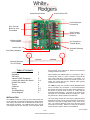
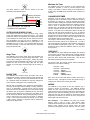
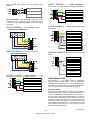
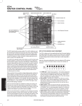
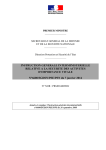
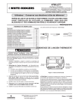
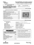
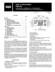
CMM-3U & CMM-3UK Zoning Panel
Installation & Operating Instructions
Product Data
•
•
•
•
•
Single Stage gas and electric systems
Multi Stage (2H/1C) gas and electric systems
Heat Pump (3H/1C)
2-3 zones
5-Year Warranty
•
•
•
•
•
•
Construction: ABS Plastic
Dimensions: 7 ⅝” x 7 ¼” x 1 ⅜”
Voltage: 24 Volts AC, 50/60 Hz
Operating Temperature: 0°- 120°
Shipping/Storage Temperature: -20°- 140°
Humidity Range: 5% - 95% Non-Condensing
•
•
•
•
CMM-3U
CLAS (leaving air sensor)
COAS (outdoor air sensor for heat pumps)
24V Transformer
•
•
•
•
CRDS – round damper (24V)
CZDS – rectangular, side mount motor (24V)
CZDB – rectangular, bottom mount motor (24V)
CSPRD – static pressure relief dampers
24V dampers are power close, spring open and are
convertible to power open, spring close
Specifications
Kit Contents (CMM-3UK)
Recommended Dampers
Recommended Thermostats
•
•
•
•
•
•
•
1F78-151 (5+2 programming)
1F78-144 (non-programmable)
1F85-0471 (5+1+1,5+2,0 programming)
1F80-0471 (5+1+1,5+2,0 programming)
1F97-1277 (7, 5+1+1,0 programming)
1F95-1277 (7, 5+1+1,0 programming)
1F85RF-275 (5+1+1,5+2,0 programming) (wireless)
Terminal
Destination
Description
W2/E….……
G……………
Y……………
R……………
W/OB………
C……………
2nd Stage Heat (Emergency heat for Heat Pumps)
Fan Relay
Compressor
Power for Heating/Cooling
Heat Relay/Changeover Valve for Heat Pump
Common Wire
To prevent electrical shock and/or
equipment damage, disconnect electric
power to system at main fuse or circuit
breaker box until installation is complete
SAVE THESE INSTRUCTIONS FOR
FUTURE USE!
Failure to read and follow all instructions
carefully before installing or operating
this control could cause personal injury
and/or property damage.
Form 37-6863A
1 of 6
© 2004 White-Rodgers by Permission
System Mode Indicator
Power Indicator LED
HVAC Equipment
Connections
Zone Terminal
Blocks for Zone
Thermostats
Zone Terminal
Blocks for Zone
Dampers
CLAS and COAS
Terminal Blocks
24V Transformer
Terminal Blocks
Sensor Limits
Automatic Resetting
Fuse
Zone Calling Indicators
Mounting Keyholes
Two at Top also.
Pump Controls, power transformer, Outdoor Air Sensor and
Leaving Air Sensor are wired.
Table of Contents
Installation
Operation
Set-Up for
Various HVAC Equipment
Leaving Air Sensor Air Sensor
Outdoor Air Sensor
Timers
Checkout
Wiring
Troubleshooting
Wiring Diagram
2
3
When installing the CMM-3U panel it is important to pick a
central location where it is most convenient to bring all the
wires. Most often this is at the furnace or air handler. It is
often the most convenient location and closest to power, the
HVAC unit controls and the zone dampers when typically
located at or near the plenum.
3
3-4
4
4
4
4-5
5-6
6
The CMM-3U panel case is made of sturdy ABS plastic and
can be mounted to any flat surface. It is recommended that
the panel be mounted to a wall or return plenum and NOT on
the furnace or plenum where it will be in contact with the
excessive hot temperatures.. The panel can be located in an
attic space or in an enclosed cabinet of a rooftop unit. Insure
the panel is not in direct exposure to the elements.
INSTALLATION
The cover easily removes from the case by pulling firmly and
separating the cover from the case exposing the circuit board.
There are 4 key-hole mounting points in each corner of the
case. The case has openings in the rear of the case as well
as the side for all wiring. Wiring can come from the back as
well as the side in order to make a neat installation.
The CMM-3U Control is a three (3) zone control panel that
can be used with conventional single stage, two stage heating
and cooling, heat pumps with or without dual fuel and up to
three stages of heating. The CMM-3U panel is the central
control panel that all zone dampers, zone thermostats, Heat
Form 37-6863A
2 of 6
© 2004 White-Rodgers by Permission
by wiring for specific applications. Below is shown the most
typical settings. Review each function for you application.
OPERATION
The CMM-3U can be controlled by conventional single stage
or heat pump thermostats. Each thermostat can then call for
heating, cooling or the fan. When a thermostat calls the panel
will keep open the damper to the calling zone, if not already
open, close the dampers to the zone(s) not calling and
activate the appropriate HVAC equipment. When opposite
calls exist for both heating and cooling the panel will allow the
zones to automatically switch between the modes. When all
zones are satisfied the panel then looks for individual fan calls
from any zone and controls the dampers based on these calls
as well. When all zone thermostats are not calling for
heating, cooling or the fan all dampers will return to a
normally open position.
1.
2.
3.
4.
Once a call for either heating or cooling is made the panel will
open the damper(s) to the zone(s) calling, close the
damper(s) to those zones not calling, activate the appropriate
controls for heating or cooling, whichever is being called and
not accept any calls for the opposite mode.
5.
Any calls for the opposite mode will be locked out until the
initial mode is either satisfied or a period of time has elapsed
that is sufficient for the first mode to satisfy, a maximum of 20
minutes. A unique sequence determines the time the unit has
been running or needs to continue to run in order to
adequately provide conditioning for each mode. If a particular
mode has already been calling for 20 minutes or longer and
an opposite call comes in the CMM-3U will immediately drop
the mode, enter the purge mode in order to dissipate the
conditioned air into the zones calling before switching over to
provide the new conditioning call to its zones.
6.
7.
When using the CMM-3U to control two stage heating, the
second stage is controlled based upon time after the first
stage call from the thermostat. When any zone calls the
panel’s built-in timer begins and after the set period of time
elapses the CMM-3U will also activate the W for second stage
heating. The Second Stage Timer is adjustable between 2,
4, 8 or 16 minutes after the first stage calls. Once the second
stage is on, it will continue to run until the first stage is
satisfied.
8.
SYSTEM – G/E OR HP This switch sets the HVAC
Output operation. In G/E the Y1 operates as first
stage cooling only. In HP position Y1 makes as the
compressor call for both heating and cooling.
HP Type – CONV or FF – This switch is used to
determine the equipment output when the System
switch is set to HP , this switch determines if the
output will be for a conventional heat pump with
electric back-up heat or fossil (dual) fuel mode.
FAN IN HEAT – YES or NO – This switch will
activates the Fan on a call for Heat in the Yes
position. In Off, the heating unit must activates the
fan when the heat is called.
FAN PURGE – YES or NO – This switch determine
if the Fan is kept on during the Purge Mode, after the
end of each heat or cool call.
STAT RV – O or B – When using HP type
thermostats this determines if the O or B terminal is
wired to the W/OB terminal on each thermostat to
determine if the call if for Heat (B) or Cool (O).
TSTAT – HC-HP Switch determines if conventional
Heat/Cool thermostats or Heat Pump thermostats
are being used for ALL zones. A conventional HC
stat would have separate W and Y output for heating
and cooling calls. A HP thermostat uses Y for both a
heat and cool call and the O or B is used to
determine whether the call is for Cooling (O) or
Heating (B).
EM HEAT – This switch sets any heat call to call for
the Emergency Heat. The Red EM HEAT LED on
the panel will light only when this switch is ON. This
is used when there is no EH switch on the
thermostats.
TEST – This switch accelerates the panel timings in
order to provide a quick checkout of all of the
functions without having to wait the full time for each
sequence.
One of the many features of the DIP switches is if at anytime
the equipment is changed from single stage to heat pump or
vice versa the thermostats do not need to be changed with
the equipment change. Changing the DIP switch settings is
all that is needed.
Once all zone thermostats are satisfied for heating and
cooling, the CMM-3U can now accept Fan calls allowing
Continuous Air Circulation (CAC) in those zones where the
thermostat’s Fan Switch is set to ON. These zone dampers
will be Open while the dampers to the zones where the Fan
Switch is set to AUTO will be CLOSED.
LEAVING AIR SENSOR (CLAS)
The Leaving Air Sensor, Model CLAS, is a remote sensor that
is located in the supply air duct to sense the Leaving Air
temperature of the HVAC Unit. The LAS is a high limit
protection for the heating and a low limit protection for the
cooling. When zoning, the airflow through the HVAC Unit is
critical. The CLAS protects the equipment in low air flow
situations as well as when by-pass air is being directed back
into the return air duct.
When all zone thermostats are satisfied for both Heating and
Cooling, and all Fan switches are set to AUTO position, the
HVAC unit will be off and all zone dampers will return to a
normally open position. Once a zone calls for heating,
cooling or fan, the dampers to the calling zones remain open
and the dampers to the zones not calling will close.
The heating limit is adjustable from 110°F to 170°F. The
cooling limit is fixed at 45°F. When the CLAS senses heating
above its set point, or cooling below its set point, the CMM-3U
will drop both all stages of heating or cooling. The CLAS
must sense a 10°F fall for heating or rise for cooling before reactivating the first stages of heating or cooling. If two stage
heating or cooling is being used the second stage timer will
start again once the first stage is re-activated.
SET-UP FOR VARIOUS HVAC EQUIPMENT
The CMM-3U is factory set for conventional heating and
cooling operation. The panel only needs to be configured
when using with an electric furnace or heat pumps.
Most all of the panel configuration is done by setting the DIP
switches in the top right of the panel. Other functions come
Form 37-6863A
3 of 6
© 2004 White-Rodgers by Permission
130
140
Minimum On Timer
150
120
The CMM-3U also has a minimum on time whenever the
compressor operates in order to prevent frequent short
cycling. Once there is a call for cooling or the compressor on
a heat pump, the CMM-3U will hold that call for a period of 2
minutes.
160
110
170
HIGH LIMIT
The CLAS requires 2 wires from the sensor to the LAS
terminals on the CMM-3U panel.
Leaving Air Sensor
In Supply Air Duct
CHANGEOVER TIMER
Whenever a call is made for either heating or cooling, the
changeover timer is activated in order to track the amount of
time heating or cooling is on. When an opposite call is made
after a first call is existing the changeover timer calculates the
amount of time the unit has already been supplying the first
mode in order to determine how long it will hold off the
opposite call. If an opposite call is made shortly after the first
call, the opposite call may be held off for as much as 20
minutes. If the first call or subsequent calls for the first call
mode has had that mode operating for up to 20 minutes
already and an opposite call comes in after 20 minutes, the
changeover timer will immediately recognize the opposite call,
shutting off the current mode, enter the purge mode and
automatically switch to the opposite mode.
The longer a call has been running up to 20 minutes, the
shorter the wait time will be for an opposite call. If a call is
over 20 minutes and an opposite call is made the changeover
will be immediate following the purge time. This intelligent
changeover timing makes the CMM-3U unique to any other
zoning system.
LAS
LAS
OAS
OAS
Outdoor Air Sensor only used with
Fossil/Dual Fuel Applications
OUTDOOR AIR SENSOR (COAS)
The Outdoor Air Sensor is used only when using a Heat
Pump with Dual/Fossil Fuel back-up furnaces. The COAS
senses the outdoor air temperature and switches the heating
control between the heat pump and the fossil fuel furnace.
The temperature set point for this is adjustable on the
Outdoor Balance Point (OBP) dial on the control panel. It is
adjustable from 5°F to 53°F. It is suggested that this be set
just above freezing to avoid the heat pump from potentially
going into Defrost mode.
21
29
37
13
45
5
CHECKOUT
53
The CMM-3U has unique features that simplify the checkout
of the system and has LED readouts that constantly indicate
the system operation. Once 24 Volt Power is applied to the
panel the Green Power LED will illuminate. This will stay
illuminated constantly when power is applied.
OBP
Stage Timer
The CMM-3U has a built-in stage timer that eliminates the
need and added cost of using two stage thermostats. On a
call for either heating the timer begins. Setting the Stage
Timer dial provides a adjustable time delay of 5 to 21 minutes
between the first and second stage calls and the same
between a second stage and third stage call of heating, if
used.
9
8
12
The System LED will provide several different indications
based upon color and if it is flashing.
Heat ON – RED
Heat Limit – RED Flashing
Cool ON - GREEN
Cool Limit - GREEN Flashing
FAN ON - AMBER
PURGE
- AMBER Flashing
15
18
5
21
STAGE TIMER
PURGE TIME
The CMM-3U has a built-in Purge Time after each call is
satisfied and provides a minimum off time before another call
is initiated. The Purge Time is set at 2minutes after all calls
for a particular mode are satisfied or when the Changeover
Timer requires a changeover due to opposing calls.
Each zone has its own small Green indicator LED next to
each zone relay. This light is lit when the specific zoning is
calling for the mode shown on the System LED.
WIRING
After all calls are satisfied or the changeover timer activates,
the Purge Timer begins and the heating or cooling, whichever
was on, is deactivated. Typically the fan may be running
during this time and the damper(s) to the last zone(s) calling
will remain open to purge the conditioned air only into those
zones that were calling for the conditioning. DIP Switch 4 can
be set ON to keep the Fan running during the Purge mode in
order to prevent the fan cycling off and back on between
modes. In the instance where the Fan staying on may create
a draft, and the frequency of opposite calls is minimal this
switch can be kept to OFF.
The CMM-3U is very simple to wire and requires only a
minimum number of connections. The CMM-3U terminal
blocks are color coded and screw-less for all wires to be
easily pushed into their respective terminal by de-pressing the
button for each point and releasing once the wire is seated.
(Solid wire can often just be pushed into the terminal without
de-pressing the button.) To remove the wire, just press its
button again and remove the wire.
Zone Dampers – The CMM-3U can power any 24VAC
damper, either 2 wire or 3 wire.
See specific wiring
instructions with the damper or inside panel cover. The three
damper motor contacts are for 24VAC power are COM
(Common), OPN (Open) and CLS (Closed). Two wire, spring
Form 37-6863A
4 of 6
© 2004 White-Rodgers by Permission
return, normally open dampers use only COM and CLS
terminals.
COM
OPN
CLS
WIRING
DIAGRAM 4 - HVAC Equipment –
Conventional Two Stage Heating and Single Stage Cooling
M1
M4
M6
Y1
G
O
W1/B
R
W2
W3/E
Zone Thermostats – The thermostats wiring will be for
Conventional single stage (Y-G-R-W-C) or Heat Pump (Y-GR-E-C and O or B). See Wiring Diagram 1and 2 each type of
thermostat.
Y1
FIRST STAGE COOL
G
FAN RELAY
W1 FIRST STAGE HEAT RELAY
R
24VAC TRANSFORMER
C
W2 SECOND STAGE HEATING RELAY
WIRING DIAGRAM 5 - .Single Speed Compressor
WIRING DIAGRAM 1 – Conventional Thermostats
Heat Pump
CONVENTIONAL THERMOSTAT
Y1
G
O
W1/B
R
W2
W3/E
C W R Y G
W2/E
G
Y
R
W/OB
C
Y
COMPRESSOR RELAY
G
FAN RELAY
O REVERSING VALVE COOL
B REVERSING VALVE HEAT
R
WIRING DIAGRAM 2 – Heat Pump Thermostat
24VAC TRANSFORMER C
W2
SECOND STAGE HEAT
E
EMERGENCY HEAT
WIRING DIAGRAM 6 - Two Speed Compressor Heat
HEAT PUMP THERMOSTAT
Pump
C O/B R Y G W2/E
Y1
G
O
W1/B
R
W2
W3/E
W2/E
G
Y
R
W/OB
C
FIRST STAGE COMPRESSOR
FAN RELAY
REVERSING VALVE COOL
REVERSING VALVE HEAT
R
24VAC TRANSFORMER C
SECOND STAGE
COMPRESSOR
THIRD STAGE/EMER HEAT
WIRING DIAGRAM 3 - HVAC Equipment – Single
Stage Heating Cooling with Gas/Electric Heating.
Y1
G
O
W1/B
R
W2
W3/E
Y1
FIRST STAGE COOL
G
FAN RELAY
TROUBLESHOOTING
The CMM-3U is a very simple control to troubleshoot,
especially with the LED indicators. The only other device
needed is a simple Volt/Ohm meter. Almost all problems can
be traced to an external component or wiring to the CMM-3U.
The following procedures can help isolate the problem.
W1 FIRST STAGE HEAT RELAY
R
24VAC TRANSFORMER
C
Zone(s) Not Calling
Each zone has a Green LED next to the zone relay when it is
calling and that calling is being recognized by the CMM-3U. If
a zone is supposed to be calling and the Zone LED is not on,
check for 24VAC across the thermostat terminal C and the Y,
if a Cool call, W if a Heat Call, or G if a Fan call. If there is no
voltage here at the panel the panel is not getting the signal
from the thermostat. The problem is mis-wiring, a broken wire
or a problem in the thermostat. To check the zone on the
panel, place jumper from R to Y, R to W or R to G to see that
the panel is operating properly.
W2 SECOND STAGE HEATING RELAY
Form 37-6863A
5 of 6
© 2004 White-Rodgers by Permission
Zone(s) Will Not Shut Off
If a zone will not stop calling, the Zone LED should still be on.
Depending on the call disconnect the Y, W or G wire from the
terminal strip. The zone will drop out. Check the thermostat
wiring for a mis-wiring or short that keeps the zone calling.
Damper Motor Checkout
To checkout the dampers, the panel provides 24VAC to the
COM and OPEN when the damper is to be open and 24VAC
to COM and CLOSE when the damper is to be CLOSED.
When any zone is calling and its Green LED is ON, there is
24VAC across COM and OPEN. The only time a damper will
close is when anther zone is calling and its zone is not calling.
In this instance there will be 24VAC across COM and CLOSE.
CMM-3U WIRING DIAGRAM
St. Louis, Missouri
Markham, Ontario
www.white-rodgers.com
Form 37-6863A
6 of 6
© 2004 White-Rodgers by Permission