1
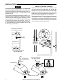
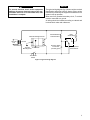
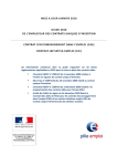
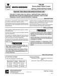
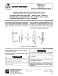
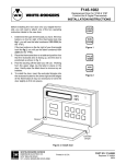
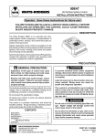
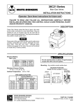
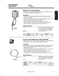
5059
WHITE-RODGERS
Pilot Relight Control
INSTALLATION INSTRUCTIONS
Operator: Save these instructions for future use!
FAILURE TO READ AND FOLLOW ALL INSTRUCTIONS CAREFULLY BEFORE INSTALLING OR OPERATING THIS CONTROL COULD CAUSE PERSONAL INJURY AND/OR PROPERTY DAMAGE.
DESCRIPTION
CA
The 5059 Pilot Relight Control is a low voltage control that
generates ignition sparks. It is energized by the thermostat on a call for heat. Once flame is established, the
control senses the flame and stops sparking. If the pilot
flame is extinguished during a call for heat, the relight
control will begin sparking immediately upon sensing
absence of flame. The control delivers very low current
sparks (approximately 6,000 volts).
W
EMEHITEUT
RSO ROD
N E GER
I
LEC S D
TRIC IV.
ON
PRECAUTIONS
If in doubt whether you wiring is millivolt, line, or low
voltage, have it inspected by a qualified heating and air
conditioning contractor, electrician, or someone familiar
with basic electricity and wiring.
Do not exceed the specification ratings.
All wiring must conform to local and national electrical
codes and ordinances.
This control is a precision instrument, and should be
handled carefully. Rough handling or distorting components could cause the control to malfunction.
! CAUTION
To prevent electrical shock and/or equipment
damage, disconnect electrical power to the system, at the main fuse or circuit box, until installation is complete.
! CAUTION
Label all wires prior to disconnection when servicing controls. Wiring errors can cause improper
and dangerous operation.
Following installation or replacement, follow
appliance manufacturer’s recommended installation/service instructions to insure proper operation.
This control is not intended for use in locations
where it may come in direct contact with water.
Suitable protection must be provided to shield
the control from exposure to water (dripping,
spraying, rain, etc.).
!
WARNING
Do not use on circuits exceeding specified voltage. Higher voltage will damage the control and
may cause shock or fire hazard.
SPECIFICATIONS
Electrical Rating:
24 VAC (30 VAC max.)
60 Hz
0.030 Amps
Mounting:
Surface mount or 2” x 4” switch box
Ambient Temperature Range:
-40°F to +175°F
WHITE-RODGERS DIVISION
EMERSON ELECTRIC CO.
Printed in U.S.A.
9797 REAVIS ROAD
ST. LOUIS, MISSOURI 63123-5398
PART NO. 37-4778B
Replaces Part No. 37-4778A
9514
INSTALLATION
INSTALL THE 5059 CONTROL
NOTE
This control requires a connection to a dead metal
ground for proper control operation (mounting screws
provided accomplish this requirement). When used in a
grounded secondary circuit, T2 terminal must be connected to ground.
Some furnace manufacturers paint their furnaces. If so,
the paint must be scraped from both sides of a furnace
where the grounded mounting hole (identified by a chassis ground symbol on the 5059 pilot relight control) comes
in contact with the furnace wall (see figs. 1 and 2). To
ensure a positive equipment ground, make a final continuity check between the control grounding hole and the
furnace using an ohmmeter.
Mount the control inside the furnace in a position so that
you have enough high voltage spark wire to reach the
electrode, but not to expose the control to excessive high
temperature conditions caused by the burner flame. The
5059 control can be mounted directly onto the furnace or
can be mounted on a standard 2” x 4” switch box.
The 5059 control has a 1⁄4” (interior) diamter terminal with
a ribbed spike. To connect a high voltage wire, cut the end
of the wire flush, to make a flat surface at the wire end.
Then push the wire end securely into the spike terminal to
ensure a proper connection (see fig. 3).
Grounding hole is identified
with chassis ground symbol
Mounting screws
V O LT A
C
AU
1⁄ 4”
spike
terminal
N
E
HI
H
G
G
TIO
Grounding hole
(indicated by
ground symbol
on 5059 control)
WHITE-RODGERS DIV.
EMERSON ELECTRIC
T1
Note: To ensure
a positive ground
connection, scrape
painted area on both
sides of furnace
T2
Figure 1. 5059 Pilot Relight
Control (top view)
Figure 2. Installing the 5059 control
Cut wire flush to
create a flat surface
1⁄4”
Push high voltage wire
onto spike; see inset
,
,
,
,
,
,
,
,
,
,
,
,
,
,
,
,
,
,,,
,
spike terminal
Cross-section of spike
connector with high voltage
wire inserted
A
5059 Pilot Relight Control
Figure 3. Installing the high voltage wire
2
B
! CAUTION
NOTE
To prevent electrical shock and/or equipment
damage, disconnect electrical power to the system at the main fuse or circuit breaker box, until
installation is complete.
The typical wiring diagram (fig. 4) shows only the terminal
identification and wiring hook-up. Always refer to wiring
instructions provided by the equipment manufacturer for
system hook-up operation.
When used in a grounded secondary circuit, T2 terminal
must be connected to a ground.
All wiring should be installed according to national and
local electrical codes and ordinances.
5059 Pilot Relight Control
Main
Valve Relay
Pilot Redundant
Solenoid Valve
C
120 VAC
Line
Transformer
H
24 VAC
Through
To Electrode
Mounting Hole
Pressure Switch
in Pilot Gas
(normally open)
Mercury Flame
Switch Sensor
Thermostat
Switch
Figure 4. Typical wiring diagram
3
If you need further information about this product, please write to
White-Rodgers Division, Emerson Electric Co.
9797 Reavis Road
St. Louis, MO 63123-5398
Attention: Technical Service Department