1
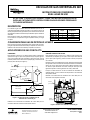
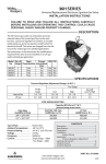
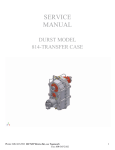
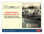
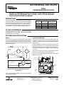
36H UNIVERSAL GAS VALVES
FIELD
CONVERSION INSTRUCTIONS
FAILURE TO READ AND FOLLOW ALL INSTRUCTIONS CAREFULLY BEFORE
INSTALLING OR OPERATING THIS CONTROL COULD CAUSE PERSONAL
INJURY AND/OR PROPERTY DAMAGE.
DESCRIPTION
The 36H universal gas valves are designed for use on automatic
spark ignition systems. The valves are shipped from the factory
set for natural gas non-piloted applications. See the Installation
Instructions included with the valves for proper installation.
This document shows the modifications required if the valve is
to be installed on an LP gas and/or piloted gas application.
Model
No.
No. of Stages
Opening
Characteristics
36H32-XXX
36H33-XXX
36H64-XXX
36H65-XXX
1
1
2
2
Fast
Slow
Fast
Slow
LP GAS CONVERSION
For LP gas conversion, use the LP conversion kit supplied
separately with this control. Refer to the instructions packed
separately with LP conversion kit.
PILOTED GAS APPLICATIONS
WIRING
PILOT GAS CONNECTION
These valves are shipped with an external wire jumper installed
for non-piloted gas applications. For applications requiring piloted
gas, such as intermittent pilot or spark-to-pilot systems, remove
the external wire jumper from the main (M) and pilot (P) valve
terminals (see figure 1).
These gas valves are shipped with the pilot outlet plugged. For
installations requiring pilot gas, remove the plug from the pilot
gas outlet (see figure 2) and use the fitting packed separately
with the valve.
SW1
C
SW2
EXTERNAL
JUMPER
P
(-)
RECTIFIER
(+)
(-)
RECTIFIER
(+)
The plug should not be removed for a Direct Burner Ignition
system such as Direct Spark or Hot Surface Ignition.
Refer to the 36H Series Installation Instructions for pilot flame
adjustment information.
SW1
SW2
Install the fitting into the pilot gas outlet, turning until finger tight.
Insert clean, de-burred ¼” O.D. tubing all the way through the
fitting. While holding the tubing securely, slowly tighten the fitting until you feel a slight “give”. Tighten the fitting an additional
1-1/2 turns.
PILOT (REDUNDANT)
M
Pilot Gas
Outlet
MAIN
TWO STAGE
MODELS ONLY
(-)
RECTIFIER
(+)
2ND
STAGE
HI
Outlet
Pressure
Tap
Figure 1. Gas valve internal wiring and terminal
identification
Main Gas
Outlet
Refer to the 36H Series Installation Instructions for additional
system wiring information.
The Emerson logo is a
trademark and a service mark
of Emerson Electric Co.
Figure 2. Gas valve outlet end
White-Rodgers is a division
of Emerson Electric Co.
www.white-rodgers.com
PART NO. 37-6658D
Replaces 37-6658C
0927
VÁLVULAS DE GAS UNIVERSALES 36H
INSTRUCCIONES DE CONVERSIÓN
EN EL LUGAR DE USO
EL NO LEER Y SEGUIR CON CUIDADO TODAS LAS INSTRUCCIONES ANTES DE
INSTALAR O UTILIZAR ESTE CONTROL PODRÍA CAUSAR LESIONES PERSONALES
Y/O DAÑOS MATERIALES.
DESCRIPCIÓN
Las válvulas de gas universales 36H están diseñadas para su uso en
sistemas de encendido de chispa automáticos. Las válvulas se envían de
fábrica para aplicaciones de gas natural sin piloto. Vea en las Instrucciones
de instalación incluidas con las válvulas el procedimiento para su instalación
adecuada.
Este documento muestra las modificaciones requeridas si la válvula se
ha de instalar en una aplicación de gas de petróleo licuado y/o de gas
con piloto.
Nº de modelo
Nº de
etapas
36H32-XXX
36H33-XXX
36H64-XXX
36H65-XXX
1
1
2
2
Características
de apertura
Rápido
Lento
Rápido
Lento
CONVERSIÓN PARA GAS DE PETRÓLEO LICUADO
Para la conversión para gas de petróleo licuado, utilice el kit de conversión
para gas de petróleo licuado suministrado por separado con este control.
Refiérase a las instrucciones incluidas por separado con dicho kit.
APLICACIONES DE GAS CON PILOTO
CONEXIONES
CONEXIÓN PARA GAS CON PILOTO
Estas válvulas se envían con un cable de puente externo instalado para
aplicaciones de gas sin piloto. Para aplicaciones que requieren gas con
piloto, como sistemas de piloto intermitente o de chispa a piloto, retire el
cable del puente externo de la terminal principal (M) y de la terminal de
piloto (P) de la válvula (vea la figura 1).
Estas válvulas de gas se envían con la salida de piloto tapada. Para
instalaciones que requieren gas con piloto, retire el tapón de la salida de
gas con piloto (vea la figura 2) y utilice el conector incluido por separado
con la válvula.
SW1
C
SW2
PUENTE EXTERNO
P
(-)
RECTIFICADOR
(+)
(-)
RECTIFICADOR
El tapón no debe retirarse en el caso de sistemas de encendido de
quemador directo, como los sistemas de chispa directa o de encendido
de superficie caliente.
(+)
SW1
SW2
Instale el conector en la salida de gas con piloto, girándolo hasta que quede
bien ajustado a mano. Introduzca un tubo limpio sin rebaba con un diámetro
externo de 1/4 pulg. hasta el final del conector. Mientras sostiene el tubo
con firmeza, ajuste lentamente el conector hasta que sienta que cede
ligeramente. Ajuste el conector girándolo una vuelta y media más.
Refiérase a las instrucciones de instalación de la serie 36H para ver
información sobre el ajuste de la llama.
PILOTO (REDUNDANTE)
M
Salida de
gas con piloto
PRINCIPAL
SÓLO MODELOS
DE DOS ETAPAS
(-)
RECTIFICADOR
(+)
ALTO
Grifo de
presión
de salida
2° ETAPA
Figura 1. Conexiones internas e identificación de
terminales de la válvula de gas
Salida de
gas principal
Refiérase a las instrucciones de instalación de la serie 36H para ver
información adicional sobre las conexiones del sistema.
El logotipo de Emerson es una marca
comercial y una marca de servicio de
Emerson Electric Co.
Figura 2. Extremo de la salida de la válvula de gas
White-Rodgers es una división
de Emerson Electric Co.
www.white-rodgers.com
Nº DE PIEZA 37-6658D
Reemplaza 37-6658C
0927