Transcript
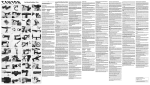
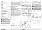
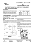
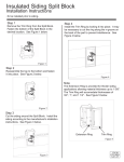
Installation and User Manual
Always have a qualified bicycle technician install the Plug If on your bicycle,
Please visit www,tout-terrain.de for a video intallation tutorial.
Please read carefulty. If the instructions are not foltowed carefully you might void your warranty!
Also make sure that the steer tube end is de-burred on in and outsade.
For installation (Hex) Allen keys size 4mm and 5mm are required,
a) check of star-fangled nut and installation of cable
General use and features:
o
consumes almost no power if no device is connected, If 5V (+/-0,2V) are supplied
the green LE D will tu rn on, rega rdless if there is a device connected or not. If there is no device connected and the internalvoltage is too high (at high speeds),the Plug II switches off automatically,
o
the Ptug II has been optimized to power devices that use USB stand- -;f"X ard as interface, Please note that the actual use and performance of r*rffi
a device in combination with the Plug II depends on the device! in- t*T--t*1"}
generdividual charging and operating characteristic, the Plug II
ally provides a power interface according to USB-specifcation type A.
This means that the USB wire L and 4 provide constant power of 5V,
o
the Plug II does only supply power once a constant output of 5V can be supplied. The actual
riding speed in order to provide 5V output depends on your device's individual charging and
operating characteristic. Please check with your device's manufacturer for compatibility and
requirements, The following chart shows a basic overview of output current depending on your
speed, This however also depends on the hub dynamo used,
the Plug
INSTALLATION
The cable (4) can be wired through the "claws" of a standard star-fangled nut. Please see
Fig,1 for details. Please make sure to not damage the cable!
If this is not an option continue with b),
II
BAD
/
SCHLECHT GOOD
/ GUT
Fls,l
b) alternative to a): Installation of expander nut with integrated cable channel (3)
Power @ Speed
1.
2.
g
tffi
Insert the expander nut (3) in the steer shaft with the cable (4) already inserted in the
channel,Tighten the expander nut using a Hex 5 Allen Key, Make sure to leave a 5mm gap
between the top of the steer shaft and the top of the stem. You might need to add a spacer,
In case you already have a star-fangled nut installed you will need to remove it uslng the following st€ps. You can either remove the star-fangled nut by forcing it out using
a hammer or by using a drilling technique. The drilling technique requires to repeat a drill
sequence through the center of the star-fangled nut by using a 6-8-10-11-12 mm drills one
after the other, until the star-fangled nut collapses.
c) connecting of cable and adjustment of headset:
1.
Z,
3,
the Plug
If
has been designed for parallel use with a light system. Thus there is no need
Please also see the light and dynamo
manufacturer's instructions for cable Installation details, However please note that if
to dismount any cable after its initial installation,
the Plug II and a light system are used at the same time, both light and the Plug II 's
output performance will decrease based on the limitation of the hub dynamo, Thus we recommend to use "either/or",
the Plug .If 's electronics have been designed to be water'resistant, However depending
on the conditions of use, the USB outlet might show some initial rust corrosion over time.
This rust film can be easily removed using a Q-tip with some alcohol,
Please note: Never rotate the USB-Top'Cap (1) after installation. as this might
damage the connector cable,
the Plus
II
manual v1,1, Juli 2011
Connect the cable (4) with the connector at the bottom of the Top Cap (1), If needed, the
cable can be disengaged using slight force.
Use your existing aheadset cap to adjust the headset. Torque the stem according to the
manufacturer's specifications, Depending on your headset you might need a shorter M6 bolt.
There is no need to pay attention to polarity of the cables as the dynamo hub has AC output'
However please also see the light and dynamo manufacturer's instructions for cable installa-
tion details.
d) Assembly of
USB cover
(2)
Slide the plastic ring of the USB cover assembly (2) over the Top Cap (1) with the pin that
fixes the silicone part facing upwards,
e) Top Cap installation
Install the Top Cap (1) like a regular Ahead-Set Cap using the M6 bolt'
NOTE: You can also the bolt of the top cap (l) to adjust the headset. In this case pay
attention that the cable does not get damaged!