1
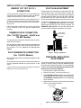
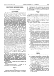
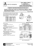
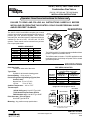
36C03, 36C10, 36C13 and 36D34
Combination Gas Valves
(24 Volt, 120 Volt and .750 Volt Models)
INSTALLATION INSTRUCTIONS
Operator: Save these instructions for future use!
FAILURE TO READ AND FOLLOW ALL INSTRUCTIONS CAREFULLY BEFORE
INSTALLING OR OPERATING THIS CONTROL COULD CAUSE PERSONAL INJURY
AND/OR PROPERTY DAMAGE.
OT
PIL
PIL
ON
ON
OFF
ECO
Terminals
OFF
The 36C03, 36C13 and 36D34 complete gas controls
combine into a single compact package the functions of 3position gas cock, pressure regulator, 100% shut-off
automatic pilot, and main operator. Separate models are
available for use on 24 VAC, 120 VAC and .750 VDC
systems. These controls can be mounted in any orientation except upside down.
OT
DESCRIPTION
MODELS AVAILABLE
Model No.
36C03
36C03A
36C03U
36C13
36C13A
36C13U
36D34U
Voltage
24 volts
120 volts
.750 volts
24 volts
120 volts
.750 volts
.750 volts
Current
Gas
.23 Amp
Nat.
.035 Amp
Nat.
DC
Nat.
.23 Amp
LP
.035 Amp
LP
DC
LP
DC
Nat./LP
The 36C03 and 36C13 models are also available without
pressure regulator as a Model 36C10.
The 36D34 model is limited to .750 VDC applications and
is equipped with a "quick drop out" power unit for vented
gas hearth products.
SPECIFICATIONS
Pilot Gas Outlet:
Located at outlet end of the valve
PIPE SIZES/CAPACITIES
Type of Gas
Suitable for all domestic heating gases
Pressure Rating: 1/2 lb. per sq. in.
Pressure Regulator Adjust Range (Typical, See
Control Label):
Natural Gas: 2.5 to 5.0" W.C.
LP Gas:
7.5 to 12" W.C.
Pipe Size
(inches)
1 ⁄2 ”
x 3 ⁄8 ”
x 1 ⁄2 ”
1 ⁄2 ” x 3 ⁄4 ”
3 ⁄4 ” x 3 ⁄4 ”
1 ⁄2 ”
Capacity (BTU/hr) at
1” pressure drop across valve
Nat. Gas
LP Gas
(1000 BTU/cu. ft., (2500 BTU/cu. ft.,
64 Sp. Gr.)
1.53 Sp. Gr.)
100,000
162,000
230,000
372,600
230,000
372,600
280,000
453,600
Ambient Temperature: -40° to 175°F
Upright, 90° from upright or vertical
Thermocouple:
(24V & 120V types): Use W-R Type HO6
INLET BOSS
UP OR DOWN
UPRIGHT
(.750V Quick Drop Out Power Unit for
36D34 models only): Use W-R Type H19E
LEFT OR RIGHT
Pilot Generator (.750 volt types):
Use W-R Type G01A-32
OFF
ON
Mounting: Any position except upside-down
NOTE: Control shown may not be identical
to replacement control.
www.white-rodgers.com
PART NO. 37-5781D
Replaces 37-5781C
0909
SPECIFICATIONS
DO NOT BEGIN INSTALLATION UNTIL YOU READ
THE FOLLOWING PRECAUTIONS.
!
WARNING
If you do not follow these instructions exactly, a fire or explosion may
result, causing property damage, personal injury or loss of life.
1. Failure to turn off electric or main gas supply
to heating system could cause personal injury and/or property damage by shock, gas
suffocation, fire, and/or explosion.
3. NEVER USE FLAME OR ANY KIND OF SPARK
TO CHECK FOR GAS LEAKS–COULD CAUSE
FIRE AND/OR EXPLOSION.
4. Do not use a control set for natural gas with
LP gas, or a control set for LP gas with
natural gas. Personal injury and/or property
damage, gas suffocation, fire, and/or explosion may result.
2. Do not use this control on circuits exceeding
specified voltage. Higher voltage will damage the control and may cause shock or fire
hazard.
!
CAUTION
1. Do not short out terminals on gas valve or
primary control to test. Short or incorrect
wiring can cause equipment damage, property damage, and/or personal injury.
2. This control is not intended for use in locations where it may come in direct contact
with water. Suitable protection must be provided to shield the control from exposure to
water (dripping, spraying, rain, etc.).
INSTALLATION
5. Apply pipe joint compound (pipe dope) or teflon tape
that is approved for all gases, only to the male
threads of the pipe joints. DO NOT apply compound or teflon tape to the first two threads (see fig. 1
for typical piping connections).
6. If you are using a vise or open-end wrench to hold the
valve while installing piping, do not tighten excessively, as this may damage the valve.
7. If additional clearance for the gas cock knob is required when installing the new valve in an existing
system, rotate the knob to the position between ON
and OFF. Depress the knob while turning the valve.
The knob will depress only while in this position.
8. See SYSTEM WIRING when making electrical connections. After all gas and electrical connections are
completed, turn gas on and check for gas leaks with
leak detection solution or soap suds. Bubbles forming
indicate a leak. SHUT OFF GAS AND FIX ALL
LEAKS IMMEDIATELY.
MAIN PIPING CONNECTIONS
NOTE
All piping must comply with local codes, ordinances,
and/or national fuel gas codes.
1. Turn off electrical power to the system at the fuse box
or circuit breaker. Also turn off the main gas supply.
2. If replacing an existing valve, disconnect all plumbing
and electrical connections from the old control.
3. The control may be installed in any orientation except
upside down. The arrow on the valve indicates the
direction of gas flow through the control.
4. You should use new pipe that is properly chamfered,
reamed, and free of burrs and chips. If you are using
old pipe, be sure it is clean and free of rust, scale,
burrs, chips, and old pipe joint compound.
2
INSTALLATION (cont’d)
PILOT GAS CONNECTION
Drop
Horizontal
Install fitting into pilot gas outlet (see fig. 2), turning until
finger-tight. Insert clean, deburred tubing all the way
through the fitting. While holding the tubing securely,
slowly tighten fitting until you feel a slight "give". Tighten
the fitting an additional 1 1/2 turns.
NOTE:
Always Include
A Drip Leg In Piping
Riser
Gas Valve
3 in.
minimum
Pilot gas
outlet
Drop
Tubing Gas
Supply
PRESS
PILOT
Gas Valve
Riser
Horizontal
TAP
Gas outlet
Gas Valve
3 in.
minimum
3 in.
minimum
Piped Gas
Supply
Piped Gas
Supply
Figure 2. Gas valve side view
Figure 1. Typical gas valve piping
SYSTEM WIRING
NOTE
! CAUTION
All wiring should be installed in accordance with local
and national electrical codes and ordinances.
To prevent electrical shock and/or equipment damage, disconnect electrical power to system at main
fuse or circuit breaker box until installation is
complete.
Always check that the electrical power supply used agrees
with the voltage and frequency shown on the gas control.
High
Limit
The typical wiring diagram shows only the terminal identification and wiring hook up. Always refer to wiring
instructions provided by Equipment Manufacturer for system hookup operation.
Thermostat
Thermostat
Gas valve
terminal panel
White-Rodgers
36C Gas Valve
High
limit
TH TH-PG
TH TH-TR
PG
TR
Hot
Power
Unit
To Pilot
Generator
Line
24 VAC
Transformer
Figure 4. Wiring for 36C03/36C13 (24 Volt)
Figure 3. Wiring for 36C03U/36C13U/36D34U (.750 Volt)
Thermocouple
Connection
Lead
Assembly
Line
E.C.O. Device
on Appliance
Line voltage
operating
control
NOTE
If appliance does not have
any E.C.O. device, jumper
E.C.O. terminals.
High
limit
E.C.O.
Terminals
Gas valve
Figure 6. Wiring for 36C03A/36C13A (120 Volt)
Figure 5. Wiring for Energy Cut-Off (E.C.O.) connection
3
INSTALLATION (cont’d)
ENERGY CUT OFF (E.C.O.)
CONNECTION
PILOT GAS ADJUSTMENT
If the pilot flame is low and does not engulf the bulb of the
mercury flame sensor, the system will not energize the
main valve. If pilot gas pressure is too high, gas will sputter
past the ignition electrode, and may not ignite. High pilot
gas pressure may also cause the flame to lift off the
burner, causing the flame sensor bulb to sense "low" heat.
A five-function valve uses the two E.C.O. terminals that are
connected to the magnetic assembly where the thermocouple connects to the 36C valve line interrupter.
Connect the leads from the E.C.O. terminals to the E.C.O.
device on the furnace. Test the E.C.O. device for continuity. If there is no continuity, the power unit will not hold in.
See figure 5.
To adjust the pilot gas pressure, remove the cover screw
(see fig. 7). To REDUCE pilot pressure, turn the pilot
adjust screw (beneath the cover screw) clockwise. To
INCREASE pilot pressure, turn the pilot adjust screw
counterclockwise. Replace and tighten cover screw.
If the furnace does not have an E.C.O. device, jumper the
E.C.O. terminals on the valve with the jumper loead
provided.
Pilot adjust
cover screw
THERMOCOUPLE CONNECTION
(For .750 VDC (Special), 24 VAC and
120 VAC Models)
Gasket
The thermocouple connection should be clean to ensure
good electrical contact.
Run the thermocouple nut into the power unit tapping as
far as possible by hand. Then use a small wrench to set
the nut with a 1/4 to 1/2 additional turn. Do not overtighten.
Pilot
adjust
screw
PILOT GENERATOR CONNECTION
(For .750 VDC Models)
Figure 7. Pilot gas adjustment
PRESSURE REGULATOR
ADJUSTMENT
Be sure the pilot generator is completely engaged into the
pilot burner.
Be sure that the two terminals from the pilot generator are
securely tightened beneath the proper screws on the
valve.
The pressure regulator has been factory adjusted (see
control for specific setting). Although additional adjustments will not normally be necessary, you may adjust the
regulator. Do not force the adjusting screw beyond the
limits that it can easily be adjusted.
Connect the power unit lead to the high limit and the
high limit to the TH-PG terminal.
1. Energize valve to ignite main burner.
2. Remove "Reg. Adj." cover screw (see fig. 8).
3. To DECREASE outlet pressure, turn the adjusting
screw (beneath the cover screw) counterclockwise.
To INCREASE outlet pressure, turn the adjusting
screw clockwise.
4. Replace the cover screw. Cycle the valve two or three
times to verify regulator setting.
Regulator adjusting
cover screw
PIL
OT
Pilot adjust
cover screw
OFF
ON
Figure 8. Pressure regulator adjustment
4
PILOT LIGHTING INSTRUCTIONS
AND PRECAUTIONS
FOR YOUR SAFETY READ BEFORE LIGHTING
!
If you do not follow these instructions exactly, a fire or explosion
may result causing property damage, personal injury or loss of life.
WARNING
A. This appliance has a pilot that must be lighted by hand.
When lighting the pilot, follow these instructions exactly.
•
Immediately call you gas supplier from a neighbor's
phone. Follow the gas supplier's instructions.
B. BEFORE LIGHTING, smell all around the appliance area
for gas. Be sure to smell next to the floor because some
gas is heavier than air and will settle on the floor.
•
If you cannot reach your gas supplier, call the fire
department.
C. Use only your hand to push in or turn the gas control knob.
Never use tools. If the knob will not push in or turn by
hand, don't try to repair it; call a qualified service technician. Force or attempted repair may result in a fire of
explosion.
FOR YOUR SAFETY
"WHAT TO DO IF YOU SMELL GAS"
•
Do not try to light any appliance.
•
Do not touch any electrical switch; do not use any
phone in your building.
D. Do not use this appliance if any part has been under water.
Immediately call a qualified service technician to inspect
the appliance and to replace any part of the control system
and any gas control that has been under water.
LIGHTING INSTRUCTIONS
7. Find pilot - follow small metal tubes from gas
control.
1. STOP! Read the precautionary information above.
2. Set the thermostat to lowest setting.
3. Turn off all electrical power to the appliance.
PILOT
BURNER
8. Turn knob on gas control counterclockwise to PILOT.
PI
OFF
LO
T
4. Depress gas control knob slightly and turn clockwise to
OFF (see fig. 9). If knob is in ON, turn clockwise to PILOT,
then depress knob slightly and turn clockwise to OFF.
ON
THERMOCOUPLE
9. Depress control knob all the way and hold in. Immediately
light the pilot with a match. Continue to hold the control
knob down for about one (1) minute after the pilot is lit.
Release knob and it will pop back up. Pilot should remain
lit. If it goes out, repeat steps 4, 5, 8, and 9.
Gas Control
Knob
•
If knob does not pop up when released, turn clockwise to
OFF, stop and immediately call your service technician or
gas supplier.
•
If the pilot will not stay lit after several tries, turn the gas
control knob to OFF and call your service technician or gas
supplier.
36C Series
NOTE: Knob cannot be turned from PILOT to OFF unless
knob is depressed slightly. Do not use tools or excessive
force.
10. Replace pilot access panel(s).
5. Wait fifteen (15) minutes to clear out any gas. If you then
smell gas, STOP! Follow B in the precautionary information above. If you don't smell gas, go to next step.
11. Turn gas control knob counterclockwise to ON.
12. Turn on all electrical power to the appliance.
6. Remove the pilot access panel(s) located under the gas
control unit.
13. Set thermostat to desired setting.
TO TURN OFF GAS TO APPLIANCE
1. Set the thermostat to lowest setting.
3. Turn gas control knob clockwise to PILOT.
2. Turn off all electrical power to the appliance if service is to
be performed.
4. Depress gas control knob slightly and turn clockwise to
OFF. Do not use tools or excessive force.
OFF
PIL
ON
OT
Gas cock
knob
Indicator
Figure 9. Gas Cock Knob
5
NOTES
6
NOTES
7
White-Rodgers is a division
of Emerson Electric Co.
The Emerson logo is a
trademark and a service mark
of Emerson Electric Co.
www.white-rodgers.com