1
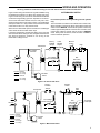
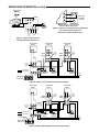
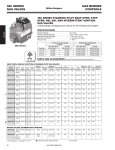
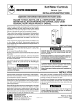
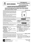
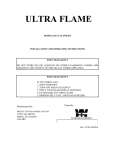
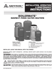
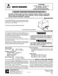
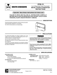
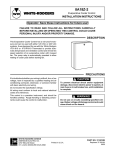
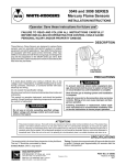
8J48A
Relay-Hot Water Control
WHITE-RODGERS
For use with 24 VAC or Self-Generating Gas Valve
(Suitable for External Zone Valve Load)
INSTALLATION INSTRUCTIONS
Operator: Save these instructions for future use!
FAILURE TO READ AND FOLLOW ALL INSTRUCTIONS CAREFULLY
BEFORE INSTALLING OR OPERATING THIS CONTROL COULD CAUSE
PERSONAL INJURY AND/OR PROPERTY DAMAGE.
DESCRIPTION
These relay-hot water controls combine a high limit control, a
transformer, a circulator relay, and wiring terminals into a single
unit. They are suitable for use on boilers equipped with a 24 volt
or millivolt gas valve.
These controls are designed primarily for use on boilers that do
not supply domestic hot water. (However, they are equipped
with an extra terminal to permit them to be used on boilers with
a tankless domestic coil by the addition of a separate SPDT low
limit-circulator control on systems using a 24 volt gas valve.)
The internal transformer supplies power for operating a gas
valve as well as the relay coil. On systems zones with motorized
water valves, the internal transformer may also be used for
powering some (or all) of the water valves.
PRECAUTIONS
If in doubt about whether your wiring is millivolt, line, or low
voltage, have it inspected by a qualified heating and air conditioning contractor, electrician, or someone familiar with basic
electricity and wiring.
Do not exceed the specification ratings.
All wiring must conform to local and national electrical codes
and ordinances.
This control is a precision instrument, and should be handled
carefully. Rough handling or distorting components could cause
the control to malfunction.
! CAUTION
To prevent electrical shock and/or equipment damage,
disconnect electric power to system, at main fuse or
circuit breaker box, until installation is complete.
! WARNING
Do not use on circuits exceeding specified voltage.
Higher voltage will damage control and could cause
shock or fire hazard.
Do not short out terminals on gas valve or primary
control to test. Short or incorrect wiring will burn out
heat anticipator. Personal injury and/or property damage may result from shorted or incorrect wiring.
SPECIFICATIONS
ELECTRICAL RATINGS
Input Voltage: 120 VAC, 60 Hz
Circulator Motor: 8.0 Amps Full Load Current (120 VAC)
48.0 Amps Locked Rotor Current (120 VAC)
Gas Valve: 24.0 VAC, 0.65 Amp OR
Millivolt Systems (0.25 to 1.0 VDC, 0.25 Amp)
Combined Load of Zone Valves:
Internal transformer (terminals TV and Z) may be used for
supplying power to four W-R Type 1311 or three Type 1361
zone Valves. (For other zone valves, total zone valve load is not
to exceed 1.2 Amp.)
WHITE-RODGERS DIVISION
EMERSON ELECTRIC CO.
9797 REAVIS ROAD
ST. LOUIS, MISSOURI 63123-5398
ROOM THERMOSTAT
Set adjustable heater (anticipator) at 0.25, or use a fixed heater
with a 0.25 Amp rating.
HOT WATER CONTROLS
Range: High Limit – 140° to 240°F. (Some models have a
Preset Dial Stop. Adjustments should be made by
authorized service personnel only.)
Differential: High Limit – 8°F Fixed
Switch Action: High Limit – Open on rise
PART NO. 37-4013C
Printed in U.S.A.
Replaces 37-4013B
9522
INSTALLATION
NOTE
If the boiler manufacturer recommends a control location, then
follow such recommendations. Otherwise, locate the control as
close to the top of the boiler as possible, but not in the same
section of the boiler that has fittings for domestic hot water.
Never locate the control near a return pipe to the boiler.
PREPARING TO MOUNT CONTROL
Slot
Capillary
Tube
This control can be mounted vertically or horizontally.
1. Loosen the set-screw holding the well in place (see fig. 1).
2. Push down and out on the well and carefully slide the
capillary tube in slot.
3. Place the well in new notch and tighten the set-screw to
secure the well in the new position.
MOUNTING THE CONTROL
1. Disconnect electrical power to the boiler.
2. Completely drain the boiler.
3. If a well tapping is not provided, prepare one near the top of
the boiler.
4. Sparingly apply pipe joint compound to the well threads and
install well.
NOTE
Use hex on well for tightening the well. Do not attempt to tighten
by using the case as a handle.
5. Refill the boiler and check for water leaks.
6. Insert the bulb element into the well until it bottoms.
7. Locate and secure the coil of excess tubing so that it cannot
touch electrical components.
8. Fit the back of the case into the well and tighten using the setscrew on the back panel.
Well
Set-screw
Figure 1
,
MOUNTING TO EXISTING WELL
(For use with well adaptor, which may be ordered separately.)
For best control performance, a well comparable to that shown
in fig. 2 is recommended. However, by using a heat conductive
grease, these controls will give satisfactory performance when
used with large-diameter existing wells. If desired, both the
conductive grease and replacement wells may be ordered
separately (see fig. 2).
A
C
B
Well No.
Description
A
1⁄2” Std. Shank
89-0211
113⁄16”
35⁄16”
89-0212 1⁄2” Std. Ext. Shank
3⁄4” Std. Shank
89-0213
113⁄16”
89-0214 3⁄4” Std. Ext. Shank
35⁄16”
89-0215 3⁄4” Extra Ext. Shank 413⁄16”
Conductive Grease No. 145-0163
B
3”
3”
3”
3”
3”
Figure 2
DIAL SETTING
When replacing an existing control, adjust the setting of the high
limit to correspond with that of the old control.
Set the pointer to the temperature at which the contacts of the
high limit are to open (see fig. 3)
Models with a preset dial stop are to be adjusted by authorized
service personnel only.
To reset the dial stop, loosen the stop adjust screw and reposition the stop to the desired setting.
Retighten the stop adjust screw.
! WARNING
DO NOT set the stop higher than the original
manufacturer’s recommended setting. Personal injury
and/or property damage may result.
2
Stop
Stop
Adjust
Screw
140
160
220
Pointer
180
200
Figure 3
C
35⁄16”
35⁄16”
35⁄16”
35⁄16”
35⁄16”
WIRING AND OPERATION
All wiring should be installed according to local and national electrical codes and ordinances.
Figure 4 shows wiring connections for a typical installation using
the 8J48A with a 36C03 or a 36C53 24V manifold gas valve.
Figure 5 shows wiring connections for the 8J48A with a 36C03U
or 36C53U self-generating gas valve. Operation is as follows:
As the room thermostat contacts close, the relay coil is energized and closes its two sets of relay contacts. The manifold gas
valve opens as the no. 1 relay contacts close, while the circulator
motor starts as the no. 2 relay contacts close.
When the room thermostat opens its contacts, the manifold gas
valve closes and the circulator motor stops.
If the boiler temperature exceeds the setting of the high limit
while the thermostat is calling for heat, the high limit will close the
gas valve but permit the circulator to run as long as the
thermostat is calling for heat.
AUTO/MANUAL SWITCH
NOTE
For manual operation of self-generating millivolt systems
only.
The manual switch, located on the outside of the controls case,
allows operation of the burner during power failures. When the
switch is set to MANUAL, the burner will operate continuously
until the high limit temperature is reached. The circulator, which
requires line voltage to operate, will not function in MANUAL
mode. When power is restored, reset the switch to AUTO to
resume automatic operation.
Factoryinstalled
Jumper
Transformer
Z
Fieldinstalled
Jumper
W
Manual
Switch
High
Limit
TP
No. 2 Relay
Contacts
Hot
B
No. 1 Relay
Contacts
C1
Low Voltage
Room Thermostat
L1
120 VAC
36C
Gas Valve
T
L2
TH TH-TR TR
C2
Neutral
TV
B2
B1
B3
INTERNAL WIRING
Line Voltage
Low Voltage
EXTERNAL WIRING
Line Voltage
Low Voltage
Circulator
Motor
Figure 4. 24 Volt AC Gas Valve
Factoryinstalled
Jumper
Transformer
Z
Manual
Switch
High
Limit
W
TP
No. 2 Relay
Contacts
Hot
B
No. 1 Relay
Contacts
C1
Low Voltage
Room Thermostat
L1
120 VAC
T
L2
Neutral
To 750 MV
Thermopile
36C
Gas Valve
TH TH-PG PG
C2
TV
B3
INTERNAL WIRING
Line Voltage
Low Voltage
EXTERNAL WIRING
Line Voltage
Low Voltage
B2
B1
Circulator
Motor
Figure 5. Millivolt Gas Valve
3
WIRING AND OPERATION (cont’d)
Thermostat
Z
8J48A
W-R
1361
Zone
Valves
Low Limit
Circulator
Control
W
T
TV
B
BL
2
1
R
W
3
Z
B1
C1
B3
C2
L1
L2
NOTE: Remove external jumper
between W and Z terminals
Circulator
Motor
Figure 7. Alternate Connections for using Separate
Low Limit-Circulator Control on
Boiler with Tankless Domestic Coil
Hot Neutral
LINE
24V
Gas
Valve
Figure 6. Typical Connections for
Zoning with 2-Wire Zone Valves
Thermostat
Zone 1
Thermostat
Zone 2
Thermostat
Zone 3
FieldInstalled
Jumper
829A
Relay
FieldInstalled
Jumper
829A
Relay
5
3
1
5
3
1
6
4
2
6
4
2
8J48A
FactoryInstalled
Jumper
Line Voltage
Low Voltage
T
W
TV
TP
Z
B
C1 C2
B1 B2 B3 L1
Circulator
Zone 1
L2
Circulator
Zone 2
Circulator
Zone 3
Neutral
120 V
36C Series
Gas Valve
Hot
TR TH-TR TH
Figure 8. 8J48A - 24 Volt Systems Zoned with Circulators
Thermostat
Zone 1
Thermostat
Zone 2
Thermostat
Zone 3
FieldInstalled
Jumper
829A
Relay
FieldInstalled
Jumper
829A
Relay
5
3
1
5
3
1
6
4
2
6
4
2
8J48A
FactoryInstalled
Jumper
Line Voltage
Low Voltage
T
W
TV
TP
Z
B
C1 C2
B1 B2 B3 L1
To 750 MV
Thermopile
L2
Circulator
Zone 1
Circulator
Zone 2
Circulator
Zone 3
Neutral
120 V
Hot
36C Series
Gas Valve
PG TH-PG TH
Figure 9. 8J48A - Millivolt Systems Zoned with Circulators