1
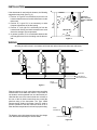
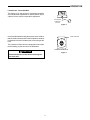
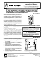
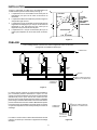
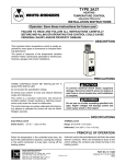
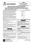
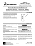
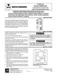
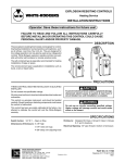
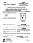
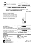
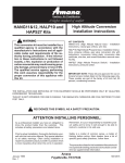
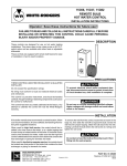
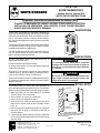
TYPE 152
ROOM THERMOSTATS
WHITE-RODGERS
Heating Service, Internal Dial
INSTALLATION INSTRUCTIONS
Operator: Save these instructions for future use!
FAILURE TO READ AND FOLLOW ALL INSTRUCTIONS CAREFULLY BEFORE
INSTALLING OR OPERATING THIS CONTROL COULD CAUSE PERSONAL
INJURY AND/OR PROPERTY DAMAGE.
DESCRIPTION
W
These room thermostats are especially designed for
controlling heating equipment operating on line voltage
with heavy electrical loads. They are suitable for operation of unit heaters, boilers, furnaces, electric heaters,
etc., or any similar application requiring a heavy duty room
thermostat.
These thermostats are ideal for use in public places where
it is desirable to have a tamper-proof control to prevent
unauthorized temperature adjustment.
This control is a precision instrument, and should be
handled carefully. Rough handling or distorting components could cause the control to malfunction.
This control has been accurately calibrated at the factory.
Any attempt to calibrate this control will void the WhiteRodgers warranty.
E
-R
O D GERS
70
80
50
60
40
PRECAUTIONS
CAUTION
THESE CONTROLS MUST BE INSTALLED BY A
QUALIFIED INSTALLER.
All wiring must conform to local and national electrical
codes and ordinances.
IT
90
The dial is inside the special locked case which requires
use of a special wrench to remove case from mounting
plate to change temperature setting.
Do not exceed the specification ratings.
H
To prevent electrical shock and/or equipment
damage, disconnect electric power to system at
main fuse or circuit breaker box until installation
is complete.
,,
,
,,,,
WARNING
Do not use on circuits exceeding specified voltages. Higher voltages will damage control and
could cause shock or fire hazard.
INSTALLATION
The proper location of a heavy duty room thermostat is
very important to assure good performance. The following
general rules will help in determining the proper location:
1. Make sure that it is in a place where air circulates
around it freely. This is important.
2. Never install it on or near an outside wall.
3. Keep it away from windows or doors.
4. Don’t locate it too close to a strong light or any other
false source of heat such as direct sunlight, steam
lines, etc.
5. Mount it on a post or a partitioning wall, but make sure
that there are no pipes or duct work in that wall or
directly behind it.
6. If the electrical conduit leads into a cooler or a warmer
room, plug up the space around the wires in the conduit
with rock wool.
WHITE-RODGERS DIVISION
EMERSON ELECTRIC CO.
9797 REAVIS RD., ST. LOUIS, MO. 63123
(314) 577-1300, FAX (314) 577-1517
9999 HWY. 48, MARKHAM, ONT. L3P 3J3
(905) 475-4653, FAX (905) 475-4625
CONCRETE
PLASTER
JUNCTION BOX
THERMOSTAT
CONDUIT
INSIDE WALL
CONDUIT
ALONG WALL
WALL INSTALLATION
The mounting plate for this thermostat has two
holes 35/16”apart for attaching the control on a
standard switch box.
Figure 1
PART NO. 37-1117B
Printed in U.S.A.
Replaces 37-1117
9605
INSTALLATION
If the thermostat is used with unit heaters, the following
suggestions may help. (See Fig. 2).
1. Position “A” is good if it is sufficiently close to the unit
heater so that the return air to the heater flows over the
thermostat.
2. Position “B” is good if it is not necessary to make
frequent adjustments of the dial setting.
3. Position “C” is all right if it is sufficiently far from the
heater that air flowing over the thermostat is not much
above the average room temperature.
4. In general, position “D” is not advisable because the
post may prevent air from circulating over the thermostat.
CEILING
POST
PARTITION
WALL OR POST
DIRECTLY BEHIND
UNIT
UNIT
B
D
A
C
RETURN AIR
FLOOR
Figure 2
WIRING
All wiring should be done in accordance with local and national electrical codes and ordinances.
SUPPLY
TYPE
11B09
TYPE
11B09
TYPE
11B09
RETURN
TO LINE SWITCH
AND POWER SUPPLY
ROOM
THERMOSTAT
Figure 3
Diagram showing a single room thermostat controlling
several steam or hot water unit heaters. Any number of
unit heaters can be operated from one thermostat provided that the sum of the motor locked rotor currents or
the sum of the full load currents does not exceed the
electrical rating of the thermostat. The Type 11B09
Reverse-acting Surface Hot Water Control is used to
prevent operation of the fans when the steam is off or
when the water temperature is too low for proper heating.
TO LINE SWITCH
AND POWER SUPPLY
ROOM
THERMOSTAT
The diagram at the right shows a heavy duty line voltage
room thermostat controlling an electric heater.
ELECTRIC HEATER
Figure 3A
2
OPERATION
Locked Case - Concealed Dial:
This feature is for the purpose of preventing tampering
and unauthorized adjustments. A special wrench is provided to remove case for temperature adjustment.
LOCK SCREW
AT BOTTOM
OF CASE
Figure 4
On a fixed differential heating thermostat, turn the dial so
that the fixed indicator points to the temperature at which
it is desired to have the contacts open, thus turning off the
heat.
FIXED INDICATOR
The contacts will then close at a temperature lower than
the dial setting, by the amount of the differential.
FIXED DIFFERENTIAL
CAUTION
Figure 5
Disconnect electric power before removing control from wall.
3
TYPE 152
THERMOSTATS MURAUX
Pour le chauffage, à cadran intérieur
INSTALLATION INSTRUCTIONS
Utilisateur : conservez ces instructions pour vous y référer au besoin !
SI VOUS NE LISEZ PAS ATTENTIVEMENT CES INSTRUCTIONS AVANT
D’INSTALLER ET D’UTILISER LA COMMANDE, VOUS RISQUEZ DE CAUSER
DES BLESSURES ET DES DOMMAGES MATÉRIELS.
DESCRIPTION
W
Ces thermostat d’ambiance ont été conçus spécialement pour
commander des installations de chauffage fonctionnant avec
des charges électriques élevées à la tension du réseau. Ils
conviennent à l’utilisation d’aérothermes, de chaudières, de
générateurs d’air chaud, d’appareils de chauffage électrique,
etc., ou de tout appareil semblable exigeant un thermostat
d’ambiance robuste.
Ces thermostats sont le choix idéal pour l’installation dans les
lieux publics où il est préférable d’utiliser une commande fermée
qui empêche n’importe qui de changer le point de consigne sans
autorisation.
Le cadran est situé à l’intérieur d’un boîtier spécial et verrouillé
qui nécessite l’utilisation d’une clé spéciale pour le démonter du
socle afin de changer le point de consigne.
H
IT
E
-R
O D GERS
90
70
80
50
60
40
PRÉCAUTIONS
LA COMMANDE DOIT ÊTRE INSTALLÉE PAR UN TECHNICIEN QUALIFIÉ.
Ne dépassez pas les charges nominales.
Tout le câblage doit être conforme aux codes et règlements
locaux et nationaux qui régissent les installations électriques.
Cette commande est un instrument de précision qui doit être
manipulé avec soin. Elle peut se détraquer si elle est manipulée
de façon négligente ou si des composantes sont déformées.
La commande a été calibrée avec précision lors de la fabrication. Toute tentative de calibrer l’appareil annulera la garantie de
White-Rodgers.
ATTENTION
Afin de prévenir les chocs électriques et les dommages
matériels pendant l’installation, coupez l’alimentation
électrique au panneau de distribution principal.
,
,
,
,
,
, ,
AVERTISSEMENT
N’installez pas cet appareil sur des circuits qui dépassent la tension nominale. Une tension trop élevée peut
endommager la commande et poser des risques de
chocs électriques et d’incendie.
INSTALLATION
Le choix d’un bon emplacement pour un thermostat d’ambiance
robuste est essentiel à son bon rendement. Les règles générales
suivantes aideront à déterminer un bon emplacement :
1. S’assurer que l’air circule librement autour du thermostat .
Ceci est important.
2. Ne jamais installer le thermostat sur un mur extérieur ou à
proximité d’un tel mur.
3. Installer le thermostat à l’écart des portes et fenêtres.
4. Ne jamais installer le thermostat près d’une source ponctuelle
de chaleur, comme les rayons du soleil, des tuyaux de
vapeur, etc.
5. Installer le thermostat sur un poteau ou une cloison intérieure
en s’assurant d’abord qu’il ne se trouve pas directement
devant des tuyaux ou des conduits.
6. Si le conduit électrique traverse un mur vers une pièce plus
chaude ou plus fraîche, placer de la laine minérale autour
des fils dans le conduit.
CONCRETE
PLASTER
JUNCTION BOX
THERMOSTAT
CONDUIT
INSIDE WALL
CONDUIT
ALONG WALL
WALL INSTALLATION
The mounting plate for this thermostat has two
holes 35/16”apart for attaching the control on a
standard switch box.
Figure 1
R
WHITE-RODGERS DIVISION
EMERSON ELECTRIC CO.
9797 REAVIS RD., ST. LOUIS, MO. 63123
(314) 577-1300, Télécopieur (314) 577-1517
9999 HWY. 48, MARKHAM, ONT. L3P 3J3
(905) 475-4653, Télécopieur (905) 475-4625
NO DE PIÈCE 37-1117B
Imprimé aux États-Unis
Remplace 37-1117
9605
INSTALLATION
Lorsque le thermostat est utilisé avec des aérothermes, les
conseils suivants peuvent s’avérer utiles (voir la fig. 2) :
1. L’emplacement A est convenable s’il est assez près de
l’aérotherme pour que l’air de retour circule autour du
thermostat.
2. L’emplacement B est convenable si le point de consigne ne
doit pas être réglé souvent.
3. L’emplacement C est convenable s’il est assez éloigné de
l’appareil de chauffage pour que l’air qui circule autour du
thermostat ne soit pas beaucoup plus chaud que la
température moyenne de l’air dans la pièce.
4. L’emplacement D n’est pas recommandé parce que le
poteau peut empêcher l’air de circuler autour du thermostat.
PLAFOND
POTEAU
CLOISON
OU POTEAU
SITUÉ
DIRECTEMENT
DERRIÈRE
L’AÉROTHERME
AÉROTHERME
B
D
A
C
AIR DE RETOUR
PLANCHER
Figure 2
CÂBLAGE
Tout le câblage doit être conforme aux codes et règlements locaux et nationaux
qui régissent les installations électriques.
ALIMENTATION
MODÈLE
11B09
MODÈLE
11B09
MODÈLE
11B09
RETOUR
VERS LE COMMUTATEUR DE
RÉSEAU ET L’ALIMENTATION
THERMOSTAT
D’AMBIANCE
Figure 3
Le schéma montre comment un seul thermostat d’ambiance
peut commander plusieurs aérothermes à vapeur ou à eau
chaude. Un seul thermostat peut commander un nombre indéfini
d’aérothermes pourvu que la somme des courants de rotor
bloqué ou des courants de pleine charge du moteur ne dépasse
pas la charge nominale du thermostat. Le thermostat de surface
pour eau chaude à action inverse modèle 11B09 sert à empêcher
le fonctionnement des ventilateurs quand la vapeur est coupée
ou quand la température de l’eau est trop basse pour assurer le
chauffage.
VERS LE COMMUTATEUR DE
RÉSEAU ET L’ALIMENTATION
THERMOSTAT
D’AMBIANCE
APPAREIL DE
CHAUFFAGE
ÉLECTRIQUE
Le schéma ci-contre montre un thermostat d’ambiance robuste
à tension du réseau qui commande un appareil de chauffage
électrique.
Figure 3A
2
MODE D’EMPLOI
Verrouillage du boîtier et cadran dissumulé :
Ceci permet de prévenir les changements et les réglages non
autorisés. Une clé spéciale est fournie qui permet d’ouvrir le
boîtier pour régler le point de consigne.
LOCK SCREW
DE BLOCAGE
AT VIS
BOTTOM
OF
CASE
SOUS
LE BOÎTIER
Figure 7
INDICATEUR FIXE
Avec un thermostat de chauffage à différentiel, tourner le cadran
pour que l’indicateur fixe indique la température à laquelle les
contacts doivent être ouverts afin de couper le système de
chauffage.
Les contacts seront ensuite fermés à toute température qui est
inférieure au point de consigne par le montant du différentiel.
DIFFÉRENTIEL FIXE
ATTENTION
Figure 5
Couper le courant avant de détacher la commande du
mur.
3