1
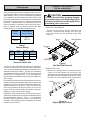
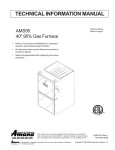
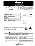
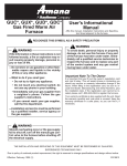
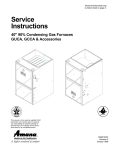
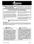
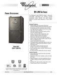
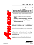
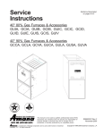
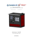
®
Heating ¡ Air Conditioning
A higher standard of comfort
HANG11&12, HALP10 and
HAPS27 Kits
WARNING
This conversion kit must be installed by a
qualified agency in accordance with the
manufacturer’s instructions and all applicable codes and requirements of the authority having jurisdiction. If the information in these instructions is not followed
exactly, a fire, explosion or production of
carbon monoxide may result causing property damage, personal injury or loss of life.
The qualified service agency performing
this work assumes responsibility for the
proper conversion of this appliance with
this kit.
High Altitude Conversion
Installation Instructions
KIT CONTENTS:
HANG11/12 (High Altitude Natural Gas) - Installation
instructions, natural gas orifices, wire ties.
HALP10 (High Altitude Propane Gas) - Installation instructions, propane orifices, gas valve conversion kits with
instructions, conversion rating plate, conversion date
certificate, wire ties, and screen/turbulator removal warning tag.
HAPS27 (High Altitude Pressure Switch) - Installation
instructions, pressure switch.
IMPORTANT NOTE: These kits are approved for use on
Amana furnace models listed on the following page only.
These models are part of the family of 40 inch tall, 90
percent, condensing furnaces.
THE INSTALLATION AND SERVICING OF THIS EQUIPMENT SHOULD BE PERFORMED ONLY BY QUALIFIED,
EXPERIENCED TECHNICIANS.
THIS KIT IS NOT INTENDED FOR USE IN CANADA. THE AMANA 90% FURNACES ARE CGA CERTIFIED TO 4500
FEET ONLY.
!
RECOGNIZE THIS SYMBOL AS A SAFETY PRECAUTION.
ATTENTION INSTALLING PERSONNEL:
As a professional installer you have an obligation to
know the product better than the customer. This
includes all safety precautions and related items.
Remember, it is your responsibility to install the product safely and to know it well enough to be able to
instruct a customer in its safe use.
Prior to actual installation, thoroughly familiarize yourself with this Instruction Manual. Pay special attention
to all safety warnings. Often during installation or
repair it is possible to place yourself in a position which
is more hazardous than when the unit is in operation.
Safety is a matter of common sense...a matter of
thinking before acting. Most dealers have a list of
specific good safety practices...follow them.
January 1999
Rev. 1
The precautions listed in this Installation Manual should
not supersede existing practices but should be considered as supplemental information.
Amana
Fayetteville, TN 37334
10314615
II. HANG11 &12, HALP10
Orifice Installation
I. Description
These kits are required when installing Amana Air Command 90 SSE furnaces above their maximum (as shipped)
rated altitudes (Table 1). Above rated altitude, a derating
of the appliance must be followed since the CFM moved
by the induced draft blower remains almost constant while
the pounds of oxygen in that air is reduced as the altitude
increases. If this procedure is not followed and the fuel
input is not reduced, combustion can be inefficient, incomplete, or possibly result in premature failure of the heat
exchanger due to an excessive temperature rise.
Furnace
Model
GUCA
GCCA
Rated Altitude
without Change
To avoid the risk of fire, property damage,
or personal injury, shut off gas supply first,
then disconnect the electrical supply before
proceeding with conversion.
1. Remove the Gas Manifold
Cut the wire ties securing the wire harness to the
manifold. Disconnect low voltage wires from gas
valve, and remove the four mounting screws (See
Figure 1).
Up To
7000 Feet
Burner
Table 1
Altitude Rating
Furnace
Model
GUCA
and
GCCA
CAUTION
Burner Bracket
Manifold
Altitude
Feet
Nat. Gas
Derate
HAPS27
(-0.16" WC)
7001-9000 ft
15.3 ± 4%
X
9001-11,000 ft 32.1 ± 4%
X
Table 2
Pressure Switch Kits
The orifices in the high altitude kits have been selected as
a result of testing with the American Gas Association.
They will provide appropriate derating at altitudes above
rated altitudes shown in Table 1. The selection is based on
non-derated gas (about 1000 BTU/Ft 3 for natural gas, and
2500 BTU/Ft 3 for propane gas). If your gas supply has
been derated for the altitude, contact your gas supplier for
orifice sizing.
Gas Valve
Figure1
Gas Manifold Removal
2. Replace Gas Orifice
a. Remove the standard altitude, natural gas orifices
(Figure 2 & 3) and replace with orifices from the
appropriate kit. Kit usage depends on an installation’s
gas usage (natural or propane) and altitude. Refer
to Table 3 or 4 for the appropriate kit requirements.
Do not derate by adjusting the manifold pressure to a lower
pressure setting other than what is specified on the furnace
nameplate. A lower air density in combination with a lower
manifold pressure at the burner orifice will prohibit the
orifice from aspirating the proper amount of air into the
burner. This can cause incomplete combustion of the gas,
flashback, and/or possible yellow tipping.
Orifices
In addition to using smaller orifices to reduce the fuel input,
a different pressure switch must be used at altitudes above
the rated altitudes shown in Table 1. A high altitude
pressure switch is required as a result of the reduction in
air density. This change is required regardless of the heat
content of the fuel used.
Figure 2
Replacing Gas Orifices
2
III. HAPS27
Pressure Switch Installation
WARNING
To avoid death or personal injury due to
electrical shock, disconnect the electrical
supply to the furnace before installing this
kit or performing any service.
Figure 3
Orifices
Furnace
Model
GUCA
GCCA
GUCA
GCCA
Kit
Number
Altitude
(Feet)
Orifice
HANG11
7001-9000
#44
HANG12
9001-11,000
#45
1. Shut off gas and disconnect power supply to furnace.
2. Locate the induced draft blower pressure switch.
Yellow and Orange
Electrical Connections
Mounting
Bracket
Screw
NOTE: Units Installed in Canada are certified to 4500 feet only,
therefore these kits are not applicable in Canada.
Table 3
Natural Gas Orifice Kits*
*
*
*
M
1
P
3
O
*
F
F
C
2
ON
*
*
*
Induced Draft Blower
Pressure Switch
* This table assumes non-derated natural gas (about
1000 BTU/Ft3). If your gas supply has been derated for
the altitude, contact your gas supplier for orifice sizing.
Furnace
Model
GUCA
GCCA
Kit
Number
Altitude
(Feet)
Orifice
HALP10
7001-11,000
#56
Induced Draft Blower
Pressure Switch
Mounting Screws
Pressure Switch
Hose
Induced
Draft
Blower
Figure 4a
Induced Draft Blower Pressure
Switch Location (GUCA)
NOTE: Units Installed in Canada are certified to 4500 feet only,
therefore these kits are not applicable in Canada.
Induced Draft Blower
Pressure Switch
Mounting Screws
Table 4
Propane Gas Orifice Kits
b. Tighten orifices with a box-end wrench. Do not use
a socket wrench, as it could damage the orifices. Do
not overtighten. Do not cross thread.
c. Reinstall the gas manifold to burner bracket assembly using screws removed in step 1. Make certain
the orifices are inserted in each burner and that each
burner remains properly seated in the burner bracket.
d. Connect low voltage gas valve wires to gas valve.
Refer to wiring diagram for proper connection.
e. Wire tie wiring harness to manifold. Make certain
wires do not interfere with gas flow from orifices or
through burners, or contact any hot surfaces.
Mounting
Bracket Screws
(Underneath Blower Deck)
Induced Draft
Blower
Induced Draft Blower
Pressure Switch
Yellow and Orange
Electrical Connections
Pressure
Switch Hose
NOTE: If converting to propane gas, see PROPANE GAS
CONVERSION section for additional instructions.
Figure 4b
Induced Draft Blower Pressure
Switch Location (GCCA)
3
WARNING
CAUTION
To avoid personal injury or property
damage due to fire, make certain all wires
disconnected from the pressure switch
during this procedure are properly
reconnected.
3. Disconnect the pressure switch hose from the pressure switch.
4. Disconnect the yellow and orange wires from pressure
switch.
5. Remove pressure switch.
Upflow (GUCA) models (Figure 4a):
Remove pressure switch mounting bracket screw securing pressure switch and mounting bracket to partition panel.
Counterflow (GCCA) models (Figure 4b):
Remove mounting bracket screws securing pressure
switch and mounting bracket to blower deck.
6. Remove screws from mounting bracket and transfer
the bracket to the HAPS27 pressure switch. Be sure
to maintain the same orientation as on the standard
altitude switch.
7. Install the HAPS27 pressure switch using screw(s)
removed in step 5.
8. Connect the yellow and orange wires to the HAPS 27
pressure switch.
9. Reconnect the pressure switch hose to new switch.
10. Verify proper furnace operation.
IV. HALP10 Propane Gas Conversion
WARNING
PERSONAL INJURY HAZARD
If your propane gas furnace is installed in
a basement, an excavated area or a
confined space, we strongly recommend
that you contact your propane supplier
about installing a warning device that would
alert you to a gas leak.
Propane gas is heavier than air and any
leaking gas can settle in any low areas or
confined spaces.
Propane gas odorant may fade, making
the gas undetectable except with a warning
device.
An undetected gas leak would create a
danger of explosion or fire. If you suspect
the presence of gas, follow the instructions
on the cover of the furnace installation
manual. Failure to do so could result in
SERIOUS PERSONAL INJURY OR DEATH.
PERSONAL INJURY HAZARD
Iron oxide (rust) can reduce the level of
odorant in propane gas. A gas detecting
device is the only reliable method to detect
a propane gas leak. Contact your propane
supplier about installing a gas detecting
warning device to alert you in the event
that a gas leak should develop.
Failure to detect a propane gas leak could
result in an EXPLOSION or FIRE which
could cause SERIOUS PERSONAL INJURY
OR DEATH.
CAUTION
To prevent unsatisfactory furnace
operation, the proper gas conversion kit
must be used for each valve. Use the WhiteRodgers spring kit only with the WhiteRodgers gas valve, Honeywell spring kit
only with the Honeywell gas valve and
Robertshaw spring kit only with the
Robertshaw gas valve. THE SPRING KITS
ARE NOT INTERCHANGEABLE.
IMPORTANT: Propane gas is heavier than air and does not
vent upward as with natural gas fuels.
1. Replace the gas valve regulator spring with one of the
new springs included in this propane gas conversion
kit.
• If the unit is equipped with a White-Rodgers 36E
gas valve, (Figures 5 & 6), use Spring Kit
#92-0659.
• If the unit is equipped with a Honeywell VR8205
gas valve, (Figure 7), use Spring Kit #393691.
• If the unit is equipped with a Robertshaw 7222
gas valve, (Figure 8), use Spring Kit #54300.
In each case, change the regulator spring per instructions included with that particular regulator spring.
Discard unused spring kits.
2. Attach the label (found in the spring kit) to the gas
valve, indicating propane conversion.
3. Attach conversion data plate, with correct input rating,
adjacent to the unit rating plate.
4. Post “conversion date certificate” on or adjacent to the
furnace.
4
Gas Valve
On/Off
Selector
Switch
O
F
F
INLET
M
1
P
3
C
2
Gas Valve
On/Off
Control Lever
In ON Position
OUTLET
ON
INLET
Inlet Pressure Tap
(Side of Valve)
Pressure Regulator
Adjustment
(Under Cap Screw)
OUTLET
Outlet (Manifold)
Pressure Tap
(Side of Valve)
Inlet Pressure Tap
(Side of Valve)
Figure 5
White-Rodgers 36E22 Gas Valve
Outlet (Manifold)
Pressure Tap
(Side of Valve)
Pressure Regulator
Adjustment
(Under Cap Screw)
Figure 8
Robertshaw Model 7222
Gas Valve
On/Off
Control Knob
V. Operational Check
INLET
OUTLET
The position of the ignitor, relative to the burner is not
affected by these conversion procedures.
1. Visually inspect the ignitor for damage. If there is
damage, replace the ignitor.
Inlet Pressure Tap
(Side of Valve)
Pressure Regulator
Adjustment
(Under Cap Screw)
Outlet (Manifold)
Pressure Tap
WARNING
To avoid the risk of fire or explosion, do
not use a flame to check for leaks.
Figure 6
White-Rodgers Model 36E36
Pressure Regulator
Adjustment
(Under Cap Screw)
Outlet (Manifold)
Pressure Tap
Honeywell
INLET
OUTLET
ON
OFF
Inlet Pressure Tap
Gas Valve
On/Off
Control Knob
Figure 7
Honeywell VR8205 Gas Valve
2. Leak test the orifice threads using a soap solution. If
leaks are found, repair before proceeding with operational check of furnace.
3. Start the furnace using the procedures found in the
furnace’s installation instructions section, “Startup Procedures and Adjustments”.
4. Check Gas Supply Pressure
The line pressure supplied to the gas valve must be
within the range specified below. The supply pressure
can be measured at the gas valve inlet pressure tap or
at a hose fitting installed in the gas piping drip leg. The
supply pressure must be measured with the burners
operating. To measure the gas supply pressure, use
the following procedure.
a. Turn OFF gas to furnace at the manual gas shutoff
valve external to the furnace.
b. Connect a calibrated water manometer (or appropriate gas pressure gauge) at either the gas valve inlet
pressure tap or the gas piping drip leg.
NOTE: At either location, a hose fitting must be
installed prior to making the hose connection.
5
Manifold Gas Pressure
Natural Gas
3.5" w.c.
Propane Gas
10.0" w.c.
Gas Line
Gas Shutoff Valve
Gas Line
To Furnace
Open To
Atmosphere
Drip Leg Cap
With Fitting
Manometer Hose
Manometer
Figure 9
Manometer
c. Turn ON the gas supply and operate the furnace and
all other gas consuming appliances on the same gas
supply line.
d. Measure furnace gas supply pressure with burners
firing. Supply pressure must be within the range
specified in the table below.
Natural Gas
Propane Gas
Inlet Gas Supply Pressure
Minimum:5.0" W.C. Maximum :10.0" W.C.
Minimum:11.0" W.C. Maximum :13.0" W.C.
If supply pressure differs from above, make necessary adjustments to pressure regulator, gas piping
size, etc., and/or consult with local gas utility.
e. Turn OFF gas to furnace at the manual shutoff valve
and disconnect manometer. Reinstall plug before
turning on gas to furnace.
f. Turn OFF any unnecessary gas appliances started
in step c.
5. Check Manifold Pressure
Only small variations in gas pressure should be made
by adjusting the gas valve pressure regulator. The
manifold pressure must be measured with the burners
operating. To measure and adjust the manifold pressure, use the following procedure.
a. Turn OFF gas to furnace at the manual gas shutoff
valve external to the furnace.
b. Connect a calibrated water manometer (or appropriate gas pressure gauge) at the gas valve outlet
pressure tap (refer to gas valve figure in previous
section).
c. Turn ON the gas supply and operate the furnace.
d. Measure gas manifold pressure with burners firing.
Adjust manifold pressure using the following table.
The final manifold pressure must not vary more than
± 0.3 “ w.c. from the above specified pressures. Any
necessary major changes in gas flow rate should be
made by changing the size of the burner orifice.
e. To adjust the gas valve pressure regulator, remove
the regulator cap.
f. Turn the adjustment screw clockwise to increase the
pressure, or counterclockwise to decrease the pressure.
g. Securely replace the regulator cap.
h. Turn OFF gas to furnace at the manual shutoff valve
and disconnect manometer.
i. Reinstall gas valve outlet pressure tap plug before
turning on gas to furnace.
6. Check Gas Input Rate (Natural Gas Only)
The gas input rate to the furnace must never be greater
than that specified on the unit rating plate. To measure
the gas input using the gas meter, proceed as follows:
a. Turn OFF the gas supply to all other gas-burning
appliances except the furnace.
b. While the furnace is operating, time and record one
complete revolution of the smallest gas meter dial.
c. Calculate the number of seconds per cubic foot
(sec/ ft3) of gas being delivered to the furnace. If the
dial is a one cubic foot dial, divide the number of
seconds recorded in step 2 by one. If the dial is a two
cubic foot dial, divide the number of seconds recorded in step 2 by two.
d. Calculate the furnace input in BTUs per hour (BTU/
hr). Input equals the sum of the installation’s gas
heating value and a conversion factor (hours to
seconds) divided by the number of seconds per
cubic foot. The measured input must not be greater
than the input indicated on the unit rating plate.
INPUT CALCULATION EXAMPLE:
Installation’s gas heating (HTG) value: 1,000 BTU/
ft3 (Obtained from gas supplier)
Installation’s seconds per cubic foot: 34 sec/ ft3
Conversion Factor (hours to seconds): 3600 sec/hr
Input = (Htg. value x 3600) ÷ seconds per cubic foot
Input = (1,000 BTU/ft3 x 3600 sec/hr) ÷ 34 sec/ ft3
Input = 106,000 BTU/hr
This measured input must agree with the derates for
your unit and altitude as indicated in Table 2 on page
2.
Derating Example 1: GUCA115AX50 at 8000 ft.
Sea level input = 115000 BTU/Hr.
From Table 1: Derate at 8000 ft. =15.3±4%
Since we are at the mid point of the elevation range, we
use the mid point of the derate; 15.3%.
New Input = 115000 x (1 - .153) = 97,405 BTU/Hr
6
Derating Example 2: GUCA115AX50 at 7001 ft.
HEAT EXCHANGER
RADIATION "LINE OF SIGHT"
Sea level input = 115000 BTU/Hr.
From Table 1: Derate at 7001 ft. = 15.3±4%
SUPPLY
AIR
Since we are at the lower end of the elevation range, we
use the lower derate: (15.3 - 4) = 11.3%
TSUPPLY
New Input = 115000 x (1 - .113) = 102,005 BTU/Hr
e. Turn ON gas and relight all other appliances turned
off in step 6a. Be certain that all appliances are
functioning properly and that all pilot burners are
operating.
7. Check The Gas Input - Propane Gas
Verify the gas input rate by checking that the appropriate orifices have been installed and the manifold
pressure has been set as stated in these instructions.
8. Check Burner Flames.
With the burner compartment door in place, check
burner flames through the view port. Flames should
be stable, soft and blue, (dust may cause orange tips
but they must not be yellow). They should extend
directly outward from the burners without curling,
floating, or lifting off.
9. Check the normal operating sequence of the ignition
system to insure burners light properly.
10. Check Temperature Rise
Temperature rise must be within the range specified
on the unit rating plate. An incorrect temperature rise
may result in condensing in or overheating of the heat
exchanger. An air flow and temperature rise table is
provided in the specification sheet. Determine and
adjust temperature rise as follows:
NOTE: At higher altitudes, the relationship between
external static pressure and temperature rise will be
different than is shown in the installation instructions,
while the relationship between CFM and temperature
rise will be approximately the same. Temperature rise
must still be within the limits shown on the unit nameplate.
a. Operate furnace with burners firing for approximately ten minutes. Ensure all registers are open
and all duct dampers are in their final (fully or
partially open) position.
b. Place thermometers in the return and supply ducts
as close to the furnace as possible. Thermometers
must not be influenced by radiant heat by being able
to “see” the heat exchanger.
7
RISE = TSUPPLY - TRETURN
TRETURN
RETURN
AIR
Figure 10
Temperature Rise Measurement
c. Subtract the return air temperature from the supply
air temperature to determine the air temperature
rise. Allow adequate time for thermometer readings
to stabilize.
d. Adjust temperature rise by adjusting the circulator
blower speed. Increase blower speed to reduce
temperature rise. Decrease blower speed to increase temperature rise.
If it is necessary to adjust the blower speed, consult
the furnace installation manual for details.
VI. Complete The Installation
Refer to the furnace installation manual for all installation
details which were not covered in this manual.