1
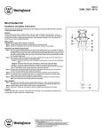
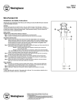
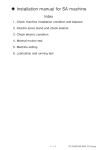
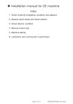
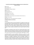
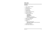
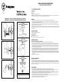
READ & SAVE THESE INSTRUCTIONS
INSTALLATION OPERATION INSTRUCTIONS
TOOLS & MATERIALS REQUIRED
Blade screw driver
Adjustable wrench
Step Ladder
Wire cutters
Wiring supplies as required by electrical code
CAUTION: Before assembling your lighting fixture, refer to the section titled ELECTRICAL CONNECTIONS. If you feel you do not have electrical wiring experience,
refer to a do-it-yourself wiring handbook or have your fixture installed by a qualified licensed electrician.
W-354
051710
"WARNING-RISK OF FIRE. MOST DWELLINGS BUILT BEFORE1985 HAVE SUPPLY
WIRE RATED 60ºC. CONSULT A QUALIFIED ELECTRICIAN BEFORE INSTALLING."
NUT
GENERAL
1. To ensure the success of the installation, be sure to read these instructions and review the diagrams thoroughly before beginning.
2. All electrical connections must be in accordance with local codes, ordinances, or the National Code. If your are unfamiliar with methods of installing electrical
wiring, secure the services of a qualified licensed electrician.
3. These fixtures are intended to be mounted to a 4”X 2 1/8” deep metal octagon outlet box. The box must be directly supported by the building structure.
4. Before starting the installation, disconnect the power by turning off the circuit breaker or by removing the fuse at the fuse box. Turning the power off using the
light switch is not sufficient to prevent electrical shock.
NOTE: The important safeguards and instructions appearing in this manual are not meant to cover all possible conditions and situations that may occur. It must be
understood that common sense, caution and care are factors which cannot be built into any product. These factors must be supplied by the person(s) caring for and
operating the fixture.
UNPACK THE FIXTURE
RUBBER PAD
Fig 1A
Check the contents of the box. You should receive:
Mounting hardware package
Lampholder assembly(s)
Mounting bracket
Shade(s)-not provided on all models
Shade attachment screws (3 for each shade)-not provided on all models
Fig 1
PREPARE THE FIXTURE
Fig 2A
Fig 2
NOTE: FIRST TURN OFF ELECTRICITY ADJUST THE CROSS BAR
1. If you are replacing an existing fixture, disconnect and remove the old fixture. Expose the supply wiring from the outlet box.
2. Some fixtures are provided with a threaded nipple (see Fig.1) or machine screws (see Fig. 2 and 2A) for attaching the fixture to the mounting bracket. If your
fixture is supplied with a threaded nipple, screw the nipple 3 complete turns into the mounting bracket and lock into place with a hexagon lock nut. If your
fixture is supplied with machine screws, thread the machine screws into the opposite side of the mounting bracket from the green ground screw. Lock the
machine screws into place with lock nuts. EXCEPTION: Ceiling mounted fixtures with keyhole slots should have machine screws entering mounting bracket
from same side as green grounding screw (see Fig.2A)
3. Fasten the mounting bracket to the outlet box using the two screws supplied with the outlet box. If your fixture is supplied with a channel shape mounting
bracket with keyhole slots for attachment to the mounting surface (see Fig.3), it will be necessary to mark the location of the keyhole slots on the mounting
surface and drill holes for fasteners (not provided). Use fasteners suitable for the mounting surface. The narrow end of the keyhole slot should face up.
4. Attach grounding wire (green or bare copper) from the supply circuit to the mounting bracket with the green grounding attachment screw provided. Some
models have a grounding wire attached to the fixture for models that employ a green or bare copper grounding wire, it will be necessary to connect the green
or bare grounding wire to the grounding conductor to the supply circuit. Attach all grounding conductors to the mounting bracket with the green grounding
attachment screw.
5. Make electrical connections-SEE BELOW.
ELECTRICAL CONNECTIONS
To make electrical connections:
Connect the white wire(s) from the fixture to the white wire of the supply circuit. Connect the black wire(s) from the fixture to the black wire of the supply circuit.
Connect the green (or bare copper) colored wire to the grounding conductor of the supply circuit. If your fixture is supplied with an SPT Cord connect the half
of the SPT Cord that is ribbed surface to the white wire of the supply circuit. Connect the smooth half of the wire (the half with markings) to the black wire of the
supply circuit. Use UL. Listed wire connectors suitable for the size, type, and number of conductors. No loose strands or loose wires should be present. Secure wire
connectors with U.L. listed electrical tape.
FINAL ASSEMBLY
Fig 3A
NOTE: The above diagram illustrates the installa tion of your new lighting
fixture. This is a representative drawing and is not intended to match the
style of your fixture.
Fig 3
1
1. Spread the electrical splices so that the black wires are on one side of the outlet box and the white wires are on the other side.
2. Place fixture against mounting surface allowing the threaded nipple or machine screws to pass through the coverplate. Secure with mounting nut or acorn
nuts. For fixtures with channel shape mounting bracket. Place the coverplate over the channel and secure with screws provided.
3. If applicable place candle cover(s) over lampholder(s) before installing bulb(s). Install the light bulb(s) (not provided). CAUTION: Refer to the relamping label
located near the lampholder for recommended maximum wattage - do not exceed recommended wattage.
4. If applicable, attach the shade to the fixture some shades require the use of shade attachment screws. Do not overtighten these screws – too much pressure
could cause glass brackage. See Fig.3 for placement of fabric spacer, not supplied on all models.
5. Outdoor wall fixtures must be caulked with suitable RTV or Silicone compound around the top and sides of the coverplate to reduce the chance of water
intruding into the splicing area. Leave the bottom clear to allow moisture a means of escape.
6. Restore electricity and check the operation of your new lighting fixture.
2
LEA Y GUARDE ESTAS INSTRUCCIONES
INSTRUCCIONES DE INSTALACIÓN Y OPERACIÓN
“ADVERTENCIA – PELIGRO DE INCENDIO – CASI TODAS LAS RESIDENCIAS- FABRICADO ANTES DE 1985.
CONTIENE CABLES DE LA FUENTE CLASIFICADO 60ºC- CONSULTAR A UN ELECTRICISTA CAPACITADO
ANTES DE INSTALAR.”
HERRAMIENTS Y MATERIALES REQUERIDOS
Destornillador reversible
Llave inglesa
Escalera de mano
Cortador de alambres
Cables de la fuente requeridos por códigos de electricidad
ADVERTENCIA: antes de instalar su artefacto de luz, refiera a la sección titulada CONEXIONES ELECTRICAS. Si Ud. siente que no tiene experiencia en la conexión
de cables, refierase a un manual de conexión de cables o solicite la instalacion de su artefacto por un electricista capacitado y acreditado
TUERCA
GENERAL
1. Para asegurar una instalación exitosa asegurese de leer las instrucciones y repase los diagramas completamente antes de comenzar.
2. Todas las conexiones electricas deben ser de acuerdo con los códigos locales, ordinanzas or El Código Nacional de Electricidad. Si Ud. no es familiarizado con
los métodos de instalacion de conexiones electricas, solicite el servicio de un electricista capacitado y acreditado.
3. Estos artefactos son intentados para ser montados a una caja profunda octagonal de enchufe con medidas de 4”x 2 1/8”. La caja debe ser soportada
directamente por la estructura del edificio.
4. Antes de comenzar la instalación debe desconectar la electricidad por medio de cortar la corriente de cortacircuitos o remover el fusible en la caja de enchufe.
Cortando la electricidad por medio del interruptor no es suficiente para prevenir ataque de electricidad.
COJIN DE GOMA
Figura 1A
Figura 1
IMPORTANTE: Los dispositivos de seguridad y las instrucciones que aparece en este manual no es intentado para cubrir todas las posibles condiciones y situaciones
que puedan ocurrir. Debe ser comprendido que el sentido comun, precaucion y cuidado son factores que no se pueden ser construidos dentro del producto. Estos
factores deben ser proporcionados por las personas que estan a cargo del producto o personas que utilizan el producto.
DESEMPACANDO EL ARTEFACTO
Verifique el contenido del carton. Debe recibir:
Paquete maquinaria del montaje
Ensamblaje de Portalámparas
Soporte de Montaje
Cortinas (no es proporcionado en todos los modelos)
Tornillos de montaje para las cortinas (3 para cada cortina)-no es proporcionado en todos los modelos
PREPARE EL ARTEFACTO
IMPORTANTE: PRIMERO, CORTE LA ELECTRICIDAD Y AJUSTESE LA BARRA TRASVERSAL
1. Si Ud. esta reemplazando un artefacto existente, desconecte y remueva el artefacto existente. Exponga los cables de la fuente desde la caja de enchufe.
2. Algunos artefactos son proporcionados con una entrerrosca roscada (vea Figura 1) or tornillos de la máquina (vea Figura 2 y 2A) para sujetar el artefacto al
soporte de montaje. Si su artefacto proporciona con una entrerrosca roscada, atornille la entrerrosca con 3 vueltas completas dentro del soporte de
montaje y trabar en lugar con una tuerca de fijación hexagonal. Si su artefacto proporciona con tornillos de la máquina, roscar los tornillos de la máquina en
el lado opuesto del soporte de montaje, desde los tornillos verdes de tierra. Trabar los tornillos de la máquina en su lugar con tuercas de fijación.
EXCEPCION: Artefactos montados en el techo con ranuras del ojo de cerradura debe tener los tornillos de la máquina entrando el soporte de montaje en el
mismo lado como los tornillos verdes de tierra. (vea Figura 2A).
3. Sujetar el soporte de montaje a la caja del enchufe usando los dos tornillos proveídos en la caja del enchufe. Si su artefacto es proporcionado con un
soporte de montaje en la forma de canal con ranuras de ojo de la cerradura para fijación en la superficie de montaje (vea Figura 3), sera necesario marcar el
lugar de las ranuras de ojo de la cerradura en la superficie de montaje y perforar agujeros para los sujetadores. (No es proveído). Usar sujetadores
apropiados para la superficie de montaje. El extremo estrecho de la ranura del ojo de la cerradura debe ser de cara arriba.
4. Sujetar alambre de tierra (verde o cobre pelado) desdel circuito de la fuente hasta el soporte de montaje con los tornillos verdes de tierra proveídos para
fijación. Algunos modelos tienen alambre de tierra sujetado al artefacto. Para modelos que utilizan alambres de tierra verde o cobre pelado, es necesario
conectar el alambre de tierra verde or pelado al conductor de tierra del circuito de la fuente. Sujetar los conductores de tierra al soporte de montaje con
tornillos verdes de tierra de fijación.
5. Hacer las conexiones eléctricas. VEA ABAJO.
Figura 2A
Figura 2
CONEXIONES ELÉCTRICAS
Para hacer conexiones eléctricas:
Conectar alambre(s) blancos desde el artefaco con el alambre blanco del circuito de la fuente. Conectar alambre(s) negros desde el artefaco con el alambre negro
del circuito de la fuente. Conectar el alambre de color verde (o cobre pelado) al conductor de tierra del ciruito de la fuente. Si su artefacto es proporcionado con
una cuerda de SPT, conectar la mitad de la cuerda del SPT que es de superficie acanalada, con el alambre blanco del circuito de la fuente. Conectar la mitad lisa del
alambre (la mitad con las marcas) con el alambre negro del circuito de la fuente. Utilizar los conectadores enumerados U.L. de alambre convenientes para el tamaño,
el tipo y el número de conductores. No debe haber filamentos flojos de conexiones flojas. Asegurar los conectadores del alambre con la cinta eléctrica enumerada U.L.
Figura 3A
NOTE: IMPORTANTE: el diagrama anterior ilustra la instalacion de su
nuevo artefacto de luz. Este es un diagrama general y no es intentado
para corresponder el estilo de su artefacto.
Figura 1
ENSAMBLAJE FINAL
1. Separar los empalmes eléctricos de modo que los alambres negros estén en un lado de la caja del enchufe y los alambres blancos estén en el otro lado.
2. Colocar el artefacto contra la superficie de montaje permitiendo las entrerroscas roscadas o los tornillos de maquina pasar a traves de la tapadera. Asegurar con
tuerca de montaje o tuerca de la bellota. Para artefactos con soporte de montaje en la forma de canal, colocar la tapadera sobre el canal y asegurar con tornillos
proveídos.
3. Si fuera applicable, colocar cubierto(s) de velas sobre portalámpara(s) antes de instalar bombilla(s). Instalar bombilla(s). (no es proveído) PRECAUCIÓN: Referir a
la etiqueta para reemplazar bombillas situada cerca de la portalámpara. Para el vatiaje recomendado - no exceder el vatiaje recomendado.
4. Si fuera applicable, sujetar las cortinas al artefacto; algunas cortinas requiren el uso de tornillos de fijación para cortinas. No debe apretar estos tornillos
demasiado, demasiada presión podría causar la fractura del cristal. Vea figura 3 para colocación del espaciador de la tela; no es proveído en todos los modelos.
5. Los montajes al aire libre de la pared deben ser rellenado con RTV conveniente o con el compuesto de silicón alrededor de la tapa y de los lados de la tapadera
para reducir la imposición del agua en el area de empalme. Dejar el fondo libre permitiendo una vía de escape para la humedad.
6. Restablecer la electricidad y comprobar la operación de su nuevo artefacto de iluminación.
3
Westinghouse Lighting Corporation, Philadelphia, PA 19154-1029, U.S.A.
Westinghou g Corporation, a Westinghouse Electric Corporation licensee
www.westinghouselighting.com
and “Westinghouse” are registered trademarks of Westinghouse Electric Corporation
et “Westinghouse” sont des marques déposées de Westinghouse Electric Corporation
Made in China / Fabriqué en Chine
© 2010 WESTINGHOUSE LIGHTING CORP.
4