1
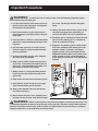
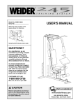
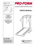
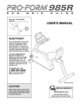
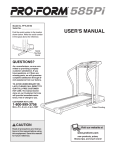
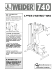
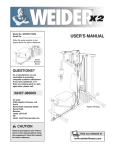
®
Model No. WEEMSY61000
Serial No.
The serial number is found in the
location shown below. Write the
serial number in the space above.
USERʼS MANUAL
Serial
Number
Decal
QUESTIONS?
As a manufacturer, we are committed to providing complete
customer satisfaction. If you have
questions, or if there are missing
parts, we will guarantee complete
satisfaction through our
Customer Service Department.
Please CALL:
0345-089009
Or WRITE:
ICON Health & Fitness Ltd.
Revie Road Industrial Estate
Revie Road
Leeds
LS11 8JG
CAUTION
Read all precautions and instructions in this manual before using
this equipment. Save this manual for future reference.
w
Visit our website at
www.weiderfitness.com
Table of Contents
Important Precautions . . . . . . . . . . . . . . . . . . . . . . . . . . . . . . . . . . . . . . . . . . . . . . . . . . . . . . . . . . . . . . . . . . . . . . 3
Before You Begin . . . . . . . . . . . . . . . . . . . . . . . . . . . . . . . . . . . . . . . . . . . . . . . . . . . . . . . . . . . . . . . . . . . . . . . . . . 4
Assembly . . . . . . . . . . . . . . . . . . . . . . . . . . . . . . . . . . . . . . . . . . . . . . . . . . . . . . . . . . . . . . . . . . . . . . . . . . . . . . . . 5
Cable Diagrams . . . . . . . . . . . . . . . . . . . . . . . . . . . . . . . . . . . . . . . . . . . . . . . . . . . . . . . . . . . . . . . . . . . . . . . . . . 19
Adjustment . . . . . . . . . . . . . . . . . . . . . . . . . . . . . . . . . . . . . . . . . . . . . . . . . . . . . . . . . . . . . . . . . . . . . . . . . . . . . . 21
Trouble-shooting and Maintenance . . . . . . . . . . . . . . . . . . . . . . . . . . . . . . . . . . . . . . . . . . . . . . . . . . . . . . . . . . . 22
Weight Resistance Chart . . . . . . . . . . . . . . . . . . . . . . . . . . . . . . . . . . . . . . . . . . . . . . . . . . . . . . . . . . . . . . . . . . . 23
Ordering Replacement Parts . . . . . . . . . . . . . . . . . . . . . . . . . . . . . . . . . . . . . . . . . . . . . . . . . . . . . . . . . Back Cover
Note: A PART LIST/EXPLODED DRAWING and a PART IDENTIFICATION CHART are attached in the centre of
this manual. Remove the PART LIST/EXPLODED DRAWING and the PART IDENTIFICATION CHART before
beginning assembly.
WEIDER is a registered trademark of ICON Health & Fitness, Inc.
2
Important Precautions
WARNING:
To reduce the risk of serious injury, read the following important precautions before using the home gym.
1. It is the responsibility of the owner to ensure
that all users of the home gym are adequately informed of all precautions.
are raised. The weights will fall with great
force.
12. Always disconnect the lat bar or nylon strap
from the home gym when performing an
exercise that does not use the attachments.
2. Read all instructions in this manual and in
the accompanying literature before using the
home gym.
13. The home gym is intended for home use only.
Do not use the home gym in a commercial,
rental or institutional setting.
3. If you feel pain or dizziness at any time whilst
exercising, stop immediately and begin cooling down.
14. Important: The warning decals shown below
have been attached to the home gym in the
locations shown. If a decal is missing or
illegible, please call our Customer Service
Department at the number on the front cover
of this manual to order a free replacement
decal. Apply the new decal in the appropriate
location.
4. Use the home gym only on a level surface.
Cover the floor or carpet beneath the home
gym for protection.
5. Inspect and tighten all parts often. Replace
any worn parts immediately.
6. Make sure the cables remain on the pulleys
at all times. If the cables bind whilst you are
exercising, stop immediately and make sure
the cables are on all of the pulleys.
7. Always stand on a foot plate when performing an exercise that could cause the home
gym to tip.
8. Keep hands and feet away from moving parts.
9. Keep children under the age of 12 and pets
away from the home gym at all times.
10. Always wear athletic shoes for foot protection when exercising.
11. Never release the press arms, butterfly arms,
leg lever, lat bar or nylon strap whilst weights
WARNING:
Before beginning this or any exercise program, consult your physician. This
is especially important for persons over the age of 35 or persons with pre-existing health problems.
Read all instructions before using. ICON assumes no responsibility for personal injury or property
damage sustained by or through the use of this product.
3
Before You Begin
Thank you for selecting the innovative and versatile
WEIDER® PRO 9930 home gym. The WEIDER® PRO
9930 offers a unique selection of weight stations
designed to develop every major muscle group of the
body. Whether your goal is to tone your body, build
dramatic muscle size and strength, or improve your
cardiovascular system, the WEIDER® PRO 9930 will
help you to achieve the results you want.
have additional questions, please contact our
Customer Service Department at 0345-089009. To
help us assist you, please note the product model
number and serial number before calling. The model
number is WEEMSY61000. The serial number can be
found on a decal attached to the home gym (see the
front cover of this manual).
Please use the drawing below to familiarise yourself with the major parts and how they fit together.
For your benefit, read this manual carefully before
using the WEIDER® PRO 9930 home gym. If you
Lat Bar
ASSEMBLED
DIMENSIONS:
Height: 198 cm
Width: 165 cm
Depth: 86 cm
High Pulley
Station
Butterfly
Arms
Backrest
Backrest
Press Arm
Curl Pad
Adjustment
Knob
Seat
Low Pulley
Station
Foot Plate
Leg Press
Lever
Weight
Stack
4
Assembly
Make Assembly Easier for Yourself!
• Two (2) adjustable wrenches
• One (1) standard screwdriver
Everything in this manual is designed to
ensure that the home gym can be assembled
successfully by anyone. Before beginning
assembly, make sure to read the information on this page. This brief introduction
will save you much more time than it takes
to read it!
• One (1) phillips screwdriver
• One (1) rubber mallet
• You will also need grease or petroleum jelly, a
small amount of soapy water, and clear tape or
masking tape.
Assembly Requires Two Persons
Note: Assembly will be more convenient if you have
a socket set, a set of open-end or closed-end
wrenches, or a set of ratchet wrenches.
For your convenience and safety, assemble the
home gym with the help of another person.
How to Identify Parts
Set Aside Enough Time
To help you identify the small parts used in assembly,
we have included a PART IDENTIFICATION CHART
in the centre of this manual. Place the chart on the
floor and use it to easily identify parts during each
assembly step. Note: Some small parts may have
been pre-attached. If a part is not in the parts
bag, check to see if it has been pre-attached.
Due to the many features of the home gym, the
assembly process will require about six hours. By
setting aside plenty of time and by deciding to
make the task enjoyable, assembly will go smoothly.
You may want to assemble the home gym over a
couple of evenings.
Select a Location for the Home Gym
How to Orient Parts
Because of its weight and size, the home gym
should be assembled in the location where it will be
used. Make sure that there is enough room to walk
around the home gym as you assemble it.
As you assemble the home gym, make sure that all
parts are oriented exactly as shown in the drawings.
Tightening Parts
Tighten all parts as you assemble them, unless
instructed to do otherwise.
How to Unpack the Box
To make assembly as easy as possible, we have
divided the assembly process into four stages. The
parts needed for each stage are found in individual
bags. Important: Wait until you begin each stage
to open the parts bag for that stage. Place all
parts of the home gym in a cleared area and
remove the packing materials. Do not dispose of
the packing materials until assembly is completed.
Questions?
If you have questions after reading the assembly
instructions, please call our Customer Service
Department at 0345-089009.
Make sure you have the following tools:
The Four Stages of the Assembly Process
Frame Assembly—You will begin by assembling
the base and the uprights that form the skeleton of
the home gym.
Arm Assembly—During this stage you will
assemble the arms and the leg lever.
Cable Assembly—During this stage you will
attach the cables and pulleys that connect the
arms to the weights.
Seat Assembly—During the final stage you will
assemble the seats and the backrests.
5
Frame Assembly
1. Before beginning, make sure that you have read
and understood the information on page 5.
1
Locate and open the parts bag labelled “FRAME
ASSEMBLY.”
Press a 2” Square Inner Cap (38) into the Butterfly
Base (61). Press two 2” Square Inner Caps (38) into
the Press Base (60).
Insert four 5/16” x 2 1/2” Carriage Bolts (1) up
through the indicated holes in the Butterfly Base (61)
and the Press Base (60). Note: If the Bolts fall out,
secure them by putting a small piece of tape over
the head of each Bolt. Place the Butterfly Base and
Press Base flat on the floor.
Attach the Press Base (60) to the Butterfly Base (61)
with two 5/16” x 2 3/4” Bolts (20), two 5/16” Flat
Washers (19), and two 5/16” Nylon Locknuts (2).
2. Position the Butterfly Upright (62) as shown. Place
the bracket on the lower end of the Butterfly Upright
(62) over the indicated 5/16” x 2 1/2” Carriage Bolts
(1) in the Butterfly Base (61). Hand tighten two 5/16”
Nylon Locknuts (2) onto the Bolts. Do not tighten the
Nylon Locknuts yet.
Place the bracket on the lower end of the Press
Frame Upright (59) over the indicated 5/16” x 2 1/2”
Carriage Bolts (1) in the Press Base (60). Hand tighten two 5/16” Nylon Locknuts (2) onto the Bolts. Do
not tighten the Nylon Locknuts yet.
61
1
38
2
2
38
19
2
1
1
60
1
Position
with the
bracket
on this
side
59
62
2
2
1
6
20
1
61
60
38
3. Place two Weight Bumpers (84) over the indicated
holes in the Butterfly Base (61). Slide the Weight
Guides (58) into the indicated holes.
3
58
8
Attach the Weight Guides (58) to the Butterfly Base
(61) with two 3/8” x 2 1/2” Bolts (6), four 3/8” Flat
Washers (17), and two 3/8” Jam Nuts (18).
Pin
Grooves
Slide the eight Weights (8) onto the Weight Guides
(58). Make sure the Weights are turned so the pin
grooves are on the bottoms of the Weights.
18
17
84
61
18
17
17
6
4. Press a Weight Tube Bumper (76) into the lower end
of the Weight Tube (77). Slide the Weight Tube into
the centre hole in the Weights (8).
4
Lubricate
78
Lubricate the holes in the Top Weight (78). Slide the
Top Weight onto the Weight Guides (58).
58
77
76
5. Press a 2” Square Inner Cap (38) into the Butterfly
Top Frame (64). Press two 1” Round Inner Caps (41)
into the top of the Butterfly Top Frame.
5
Attach the Butterfly Top Frame (64) to the Press Top
Frame (63) with two 5/16” x 2 3/4” Bolts (20), two
5/16” Flat Washers (19), and two 5/16” Nylon
Locknuts (2).
38
41
64
8
2
38
Press a 2” Square Inner Caps (38) into the end of the
Press Top Frame (63).
7
38
19
2
20
19
63
6. Hold the Butterfly Top Frame (64) and the Press Top
Frame (63) on the indicated brackets on the Uprights
(59, 62) and the Weight Guides (58). Note: Before
attaching the Top Frames to the Uprights, make
sure that both Weight Guides (58) are positioned
inside of the indicated holes.
6
46
18
17
64
Attach the Butterfly Top Frame (64) and the Press
Top Frame (63) to the Uprights (59, 62) and Weight
Guides (58) with four 5/16” x 2 3/4” Bolts (20), two
Top Plates (46), and four 5/16” Nylon Locknuts (2).
Do not tighten the Nylon Locknuts yet.
17
2
62
7
20
17
Holes
6
58
Secure the Weight Guides (58) to the Butterfly Top
Frame (64) and to the Press Top Frame (63) with two
3/8” x 2 1/2” Bolts (6), four 3/8” Flat Washers (17),
and two 3/8” Jam Nuts (18).
7. Turn the Seat Brace (75) so the nut is on the side
shown. Attach the Seat Brace to the Butterfly Base
(61) with the indicated 5/16” x 2 1/2” Carriage Bolts
(1) and two 5/16” Nylon Locknuts (2). Do not tighten
the Nylon Locknuts yet.
20
46
63
17
2
59
Nut
75
2
61
1
8. Hold the Seat Bar (74) between the Seat Brace (75)
and the Butterfly Upright (62) so that the hole that is
closest to the welded plate is facing the Seat Brace.
Attach the Seat Bar to the Seat Brace with two 5/16”
x 2 3/4” Bolts (20), two 5/16” Flat Washers (19), and
two 5/16” Nylon Locknuts (2). Do not tighten the
Nylon Locknuts yet. Note: Be careful not to overtighten the Nylon Locknuts or the curl post
attached in step 38 will not slide freely.
Attach the Seat Bar (74) to the Butterfly Upright (62)
with two 5/16” x 2 3/4” Bolts (20), two 5/16” Flat
Washers (19), and two 5/16” Nylon Locknuts (2).
Important: Tighten all Nylon Locknuts used in
steps 1 through 8.
8
8
74
20
Hole
19
62
2
19
19
75
20
Arm Assembly
9
9. Locate and open the parts bag labelled “ARM
ASSEMBLY.”
53
See the inset drawing. Orient the Press Frame (53) as
shown. Lubricate a 3/8” x 8” Bolt (30). Attach the
Press Frame to the Press Base (60) with the Bolt, two
1” x 7/8” Plastic Bushings (29), and a 3/8” Nylon
Locknut (4). Do not overtighten the Nylon Locknut.
The Press Frame must pivot easily.
10. Press a 1 3/4” Square Inner Cap (37) into the top of a
Press Arm (54). Press a 1” Inner Cap (80) into the
indicated hole in the Press Arm.
30
4
Lubricate
29
53
60
10
37
Attach the Press Arm (54) to the bracket on the Press
Frame (53) with two 5/16” x 2 1/2” Bolts (3) and two
5/16” Nylon Locknuts (2).
80
37
Repeat this step to assemble the second Press Arm
(54).
54
80
2
11. Press a 1 1/2” Square Inner Cap (79) into the Press
Seat Frame (52).
Slide the bracket on the Press Seat Frame (52) onto
the indicated 5/16” x 2 1/2” Carriage Bolts (1) in the
Press Base (60). Tighten two 5/16” Nylon Locknuts
(2) onto the Bolts.
Attach the Press Seat Frame (52) to the Press Frame
Upright (59) with two 5/16” x 2 3/4” Bolts (20), two
5/16” Flat Washers (19), and two 5/16” Nylon
Locknuts (2).
53
11
2
59
20
52
19
2
2
19
1
9
3
60
79
12. Press two 1 1/2” Square Inner Caps (79) into the Leg
Lever (49).
12
52
Insert a Bumper (33) between the brackets on the Leg
Lever (49). Secure the Bumper to the Leg Lever with a
#10 x 1” Screw (32).
32
Slide the bracket on the Leg Lever (49) onto the Press
Seat Frame (52). Attach the Leg Lever to the Press Seat
Frame with a 5/16” x 2 1/4” Bolt (81) and a 5/16” Jam
Nut (90). Do not overtighten the 5/16” Jam Nut. It
must be easy for the Leg Lever to pivot.
Attach a 3/8” x 2 1/2” Eye Bolt (83) to the Leg Lever (49)
with a 3/8” Flat Washer (17) and 3/8” Nylon Locknut (4).
13. Press a 1 3/4” Square Inner Cap (37) into each end of
the Right Butterfly Arm (68). Wet the lower end of the
Arm with soapy water. Slide a 10” Pad (65) onto the
lower end of the Arm.
33
13
Lubricate the indicated axle on the Butterfly Top Frame
(64). Have a second person slide the Right Butterfly Arm
(68) onto the axle, as shown. Refer to the inset drawing. Place two 1” Retainers (25), with the teeth downward, on top of an inverted Round Cap (26). Using a
hammer, tap the Round Cap and the Retainers onto
the axle to secure the Right Butterfly Arm.
Identify the Short Cable (71). It is approximately 1,9
m long and it has a closed loop on each end. Slide
one end of the cable onto each of the 3/8” x 1” Bolts
(15). Secure the Cable to the Bolts with 3/8” Jam Nuts
(18). Do not overtighten the Nylon Jam Nuts.
Remove both 3 1/2” Pulleys (5) from the pre-assembled
Adjustable Pulley Plates (44). Wrap the Short Cable (71)
around a 3 1/2” Pulley (5) in the direction shown. Attach
the 3 1/2” Pulley and a Cable Trap (39) to the top hole in
the two Adjustable Pulley Plates (44) with a 3/8” x 2” Bolt
(35) and a 3/8” Nylon Locknut (4). Make sure the Cable
Trap and Pulley Plates are oriented as shown.
10
17
79
25
37
26
37
Cable Assembly
Insert two 3/8” x 1” Bolts (15) into the welded brackets
on the Left and Right Butterfly Arms (67, 68). Secure the
Bolts with a 3/8” Jam Nut (18).
83
4
Lubricate
65
14. Open the parts bag labelled “CABLE ASSEMBLY
AND PULLEYS.” For cable identification and routing
during steps 14–32, refer to the CABLE DIAGRAMS
and CABLE ID CHART on pages 19 and 20.
49
79
64
68
Repeat this step to assemble the Left Butterfly Arm (67).
81
90
25
67
64
Teeth
26
14
15
68
18
15
67
18
71
5
39
4
35
44
15. Wrap the Short Cable over a “V” Pulley (21) as
shown. Attach the “V” Pulley and a Long Cable Trap
(14) to one side of the welded bracket on the Butterfly
Upright (62) with a 3/8” x 2 1/2” Bolt (6) and a 3/8”
Nylon Locknut (4).
Attach another “V” Pulley (21) and a Long Cable Trap
(14) to the other side of the welded bracket on the
Butterfly Upright (62) in the same manner.
15
6 21
62
Welded
Bracket
71
16. Identify the Medium Cable (72). It is approximately
3,5 m long and it has a ball on one end and a
threaded shaft on the other. Wrap the Medium
Cable over the 3 1/2” Pulley (5) as shown. Attach the
Pulley to the Press Top Frame (63) with a 3/8” x 3
1/2” Bolt (24), one 3/8” Flat Washer (17), and a 3/8”
Jam Nut (18).
Wrap the Medium Cable (72) over a 3 1/2” Pulley (5)
as shown. Attach the Pulley and a Cable Trap (39) to
the Press Top Frame (63) with a 3/8” x 3 3/4” Bolt (7).
18. Route the threaded shaft on the Medium Cable (72)
under one of the 3 1/2” Pulleys (5) that is already
mounted in the Double “U”-Bracket (36). Tighten the
3/8” x 1 3/4” Bolt (22).
4 21
14
63
5
18 17
17
39
2
5
24
Pin
72
7
72
63
18
72
5
36
11
6
16
Make sure the Medium Cable (72) is between the
3 1/2” Pulley (5) and the welded pin on the Press
Top Frame (63).
17. Note: It may be helpful to loosen the indicated
Nylon Locknuts (2) before beginning this step.
14
22
19. Wrap the Medium Cable (72) over a 4 1/2” Pulley
(34) in the direction shown. Attach the Pulley to the
Butterfly Top Frame (64) with a 3/8” x 1 3/4” Bolt (22)
and a 3/8” Nylon Locknut (4).
19
64
22
4
34
72
20. Attach the threaded shaft on the Medium Cable (72)
to the Small “U”-Bracket (43) with a 1/4” Flat Washer
(11) and a 1/4” Nylon Locknut (16). Note: See the
inset drawing. Do not completely tighten the
Nylon Locknut; it should be threaded only two
turns onto the end of the Cable.
20
43
11
16
Attach the Small “U”-Bracket (43) to the hole in the
Weight Tube (77) with a 5/16” x 1 3/4” Bolt (9) and a
5/16” Nylon Locknut (2).
72
2
9
77
72
11
43
21. Identify the Long Cable (73). It is approximately
7,6 m long and it has a ball on one end and a loop
on the other. Route the end with the loop through the
slot in the cable guide on the Butterfly Base (61).
Route the Long Cable (73) under a 3 1/2” Pulley (5)
as shown. Attach the Pulley and a Cable Trap (39) to
the indicated bracket on the Butterfly Base (61) with a
3/8” x 2” Bolt (35) and a 3/8” Nylon Locknut (4). Make
sure the Cable Trap is oriented as shown.
21
Cable
Guide
73
12
61
4
5
39
35
16
22. Wrap the Long Cable (73) around a 3 1/2” Pulley (5)
in the direction shown. Attach the Pulley and a Cable
Trap (39) to the Butterfly Upright (62) with a 3/8” x
3 3/4” Bolt (7), a 3/8” Flat Washer (17), and a 3/8”
Nylon Locknut (4). Make sure the Cable Trap is oriented as shown.
22
44
39
Wrap the Long Cable (73) over a 3 1/2” Pulley (5) in
the direction shown. Re-attach the Pulley and a Cable
Trap (39) to the lower hole in the Adjustable Pulley
Plates (44) with a 3/8” x 2” Bolt (35) and a 3/8” Nylon
Locknut (4). Make sure the Cable Trap is oriented
as shown.
4
35
4
5
62
17
5
39
73
23. Wrap the Long Cable (73) around a 3 1/2” Pulley (5)
in the direction shown. Attach the Pulley and a Cable
Trap (39) to the indicated bracket on the Butterfly
Base (61) with a 3/8” x 2” Bolt (35) and a 3/8” Nylon
Locknut (4).
23
35
5
7
73
61
39
Bracket
24. Wrap the Long Cable (73) around a 3 1/2” Pulley (5).
Attach the Pulley and a Cable Trap (39) to the indicated bracket on the Butterfly Base (61) with a 3/8” x 2”
Bolt (35) and a 3/8” Nylon Locknut (4).
4
24
35
5
73
39
4
61 Bracket
13
25. Note: For clarity, this and the following drawings
show some parts removed.
Remove the lower 3 1/2” Pulley (5) from the Double
“U”-Bracket (36). Then, wrap the Long Cable (73)
over the Pulley (5) in the direction shown. Attach the
Pulley to the Double “U”-Bracket (36) with a 3/8” x 1
3/4” Bolt (22) and a 3/8” Nylon Locknut (4). Make
sure the Double “U”-Bracket is oriented as
shown.
26. Wrap the Long Cable (73) around a 3 1/2” Pulley (5)
in the direction shown. Attach the Pulley and a Cable
Trap (39) to the indicated bracket on the Press Base
(60) with a 3/8” x 2” Bolt (35) and a 3/8” Nylon
Locknut (4). Make sure the Cable Trap is oriented
as shown.
25
4
36
22
5
73
26
73
5 35
39
4
27. Attach a 3 1/2” Pulley (5) and a Cable Trap (39) to
the Press Frame Upright (59) with a 3/8” x 4 3/4” Bolt
(23).
60
27
59
Wrap the Long Cable (73) around the 3 1/2” Pulley
(5) in the direction shown. Hand tighten a 3/8” Nylon
Locknut (4) two turns onto the 3/8” x 4 3/4” Bolt. In
step 31, another Pulley will be attached to the Bolt.
5
39
4
28. Route the Long Cable (73) through the opening in the
Press Frame (53) and wrap the Long Cable around a
3 1/2” Pulley (5) in the direction shown. Then, route
the Long Cable back through the opening in the
Press Frame.
Attach the 3 1/2” Pulley (5) and a Cable Trap (39) to
the indicated hole in the Press Frame (53) with a 3/8”
x 3 1/4” Bolt (28), a 3/8” Flat Washer (17), and a 3/8”
Nylon Locknut (4). Make sure the Pulley is mounted on the inside of the Press Frame (53). Make
sure the Cable Trap is oriented as shown.
14
73
23
28
73 39
4
5
53 17
28
29. Wrap the Long Cable (73) around a “V”-Pulley (21) in
the direction shown. Attach the “V”-Pulley and a
Large Cable Trap (14) to the small tube on the Press
Seat Frame (52) with a 3/8” x 3 1/4” Bolt (28), a 3/8”
Flat Washer (17) and a 3/8” Nylon Locknut (4). Note:
The small tube has three adjustment holes. Mount
the “V”-Pulley in the hole farthest from the Press
Frame Upright (59). Make sure the Cable Trap is
oriented as shown.
29
17
4
21
73
17
28
31
Remove the 3/8” Nylon Locknut (4) from the 3/8” x 4
3/4” Bolt (23) that was inserted in step 27. Attach the
Pulley and a Cable Trap (39) to the Bolt and secure
the Pulley with the 3/8” Nylon Locknut (4). Make sure
the Cable Trap is oriented as shown.
4
32. Note: Lift the top weight on the weight stack in
order to create slack in the Long Cable (73)
before beginning this step.
73
30
Attach the 3 1/2” Pulley (5) and a Cable Trap (39) to
the indicated hole in the Press Frame (53) with a 3/8”
x 3 1/4” Bolt (28), a 3/8” Flat Washer (17), and a 3/8”
Nylon Locknut (4). Make sure the Pulley is mounted on the inside of the Press Frame. Make sure
the Cable Trap is oriented as shown.
31. Route the Long Cable (73) around a 3 1/2” Pulley (5)
and back through the opening in the Press Frame
(53).
52
14
28
30. Route the Long Cable (73) back through the opening
in the Press Frame (53) and wrap the Long Cable
around a 3 1/2” Pulley (5) in the direction shown.
Then, route the Long Cable back through the opening
in the Press Frame.
59
39
53
4
5
39
5
23
53
73
32
Attach the Long Cable (73) to the Leg Lever (49),
slipping the looped end of the Cable through the
looped end of the Eye Bolt (83).
83
73
15
49
Seat Assembly
33
51
33. Locate and open the parts bag labelled “SEAT
ASSEMBLY.”
Insert a 1/4” x 2” Carriage Bolt (85) through the centre hole in a Seat Plate (42). Attach the Seat Plate to
a Seat (51) with two 1/4” x 3/4” Screws (13).
11
Insert the 1/4” x 2” Carriage Bolt (85) into the indicated hole in the Press Seat Frame (52) and secure it
with a 1/4” Flat Washer (11) and a 1/4” Nylon Locknut
(16). Secure the other end of the Seat (51) with a 1/4”
x 2” Bolt (86) and a 1/4” Flat Washer (11).
34. Press four 3/4” Round Inner Caps (40) into the ends
of the Pad Tubes (48).
Insert the Pad Tubes (48) into the indicated holes in
the Leg Lever (49) and the Press Seat Frame (52).
Slide Foam Pads (47) onto the ends of the Pad
Tubes.
Insert the 1/4” x 2 1/2” Carriage Bolt (12) with a 1/4”
Flat Washer (11) into the indicated hole in the Press
Frame Upright (59) and secure it with a 1/4” Nylon
Locknut (16).
Secure the other end of the Press Backrest (89) with
a 1/4” x 2 1/2” Screw (10) and a 1/4” Flat Washer
(11).
16
42
13
86
11
16
34
52
47
35. Insert a 1/4” x 2 1/2” Carriage Bolt (12) through the
centre hole in a Seat Plate (42). Attach the Seat Plate
to the Press Backrest (89) with two 1/4” x 3/4” Screws
(13).
85
35
40
48
49
10
89
11
16
11
47
59
13
42
12
52
40
36. Insert a 1/4” x 1 1/2” Carriage Bolt (82) through the
centre hole in a Seat Plate (42). Attach the Seat Plate
to a Seat (51) with two 1/4” x 3/4” Screws (13).
36
Insert the 1/4” x 1 1/2” Carriage Bolt (82) into the indicated hole in the Seat Bar (74) and secure it with a
1/4” Flat Washer (11) and a 1/4” Nylon Locknut (16).
Secure the other end of the Seat (51) with a 1/4” x
1 1/2” Screw (88) and a 1/4” Flat Washer (11).
51
13
82
42 74
11
16
37. Attach the Backrest (66) to the Butterfly Upright (62)
with two 1/4” x 2 1/2” Screws (10) and two 1/4” Flat
Washers (11).
88
37
11
10
62
66
Miscellaneous Assembly
38
38. Attach the Curl Pad (69) to the Curl Post (70) with two
1/4” x 3/4” Screws (13).
69
11
70
13
Insert the Curl Post (70) into the Seat Brace (75) and
secure the Curl Post at the desired height with the
Adjustment Knob (45).
45
17
75
39. Apply the WEIDER PRO 9930 decal in the location
shown.
39
WEIDER
PRO 9930
40. Make sure that all parts have been properly tightened. The use of the remaining parts will be explained in
ADJUSTMENT, beginning on page 21 of this manual.
Before using the home gym, pull each cable a few times to make sure that the cables move smoothly over
the pulleys. If one of the cables does not move smoothly, find and correct the problem. IMPORTANT: If the
cables are not properly installed, they may be damaged when heavy weight is used. See the CABLE
DIAGRAMS on pages 19 and 20 of this manual for proper cable routing. If there is any slack in the
cables, you will need to remove the slack by tightening the cables. See TROUBLE-SHOOTING AND
MAINTENANCE on page 22.
18
Cable Diagrams
The Cable Diagrams below and on the next page show the proper routing of the Short Cable (71), the Medium
Cable (72), and the Long Cable (73). The numbers show the correct route for each Cable. Make sure that the
Cables are routed correctly, that the Pulleys move smoothly, and that the Cable Traps do not touch or
bind the Cables. Incorrect cable routing can damage the home gym.
Short Cable (71)
Medium Cable (72)
1
2
5
4
2
1
4
3
3
5
Cable ID Chart
(71) 1,9 m
(72) 3,5 m
(73) 7,6 m
19
Long Cable (73)
6
3
4
1
5
10
7
2
8
12
20
11
9
13
Adjustment
The instructions below describe how each part of the home gym can be adjusted. IMPORTANT: When using an
attachment, make sure it is in the correct starting position for the exercise to be performed. If there is
any slack in the cables or chain as an exercise is performed, the effectiveness of the exercise will be
reduced.
CHANGING THE WEIGHT SETTING
To change the setting of the weight stack, insert a Weight
Pin (87) under the desired Weight (8). Make sure you
insert the Weight Pin as far as it will go. Note: Due to the
cables and pulleys, the amount of resistance at each
exercise station may vary from the weight setting.
Use the WEIGHT RESISTANCE CHART on page 23 to
find the approximate amount of resistance at each
weight station.
8
ATTACHING THE LAT BAR OR NYLON STRAP TO
THE HIGH PULLEY STATION
87
72
Attach the Lat Bar (50) to the Medium Cable (72) with a
Cable Clip (57). For some exercises, the Chain (55)
should be attached between the Lat Bar and the Medium
Cable with two Cable Clips. Adjust the length of the
Chain between the Lat Bar and the Medium Cable so
the Lat Bar is in the correct starting position for the
exercise to be performed.
56
55
57
50
The Nylon Strap (56) can be attached in the same manner.
ATTACHING THE LAT BAR OR NYLON STRAP TO
THE LOW PULLEY STATION
Attach the Lat Bar (50) to the Long Cable (73) with a
Cable Clip (57). For some exercises, the Chain (55)
should be attached between the Lat Bar and the Long
Cable with two Cable Clips. Adjust the length of the
Chain between the Lat Bar and the Long Pulley Cable
so the Lat Bar is in the correct starting position for
the exercise to be performed.
56
55
The Nylon Strap (56) can be attached in the same manner.
USING THE CURL PAD
To use the Curl Pad (69), insert the Curl Post (70) into the
Seat Brace (75) and secure the Curl Post at the desired
height with the Adjustment Knob (45).
69
70
45
75
21
73
57
Trouble-shooting and Maintenance
Inspect and tighten all parts each time you use the home gym. Replace any worn parts immediately. The
home gym can be cleaned using a damp cloth and mild non-abrasive detergent. Do not use solvents.
TIGHTENING THE CABLES
The type of cable used on the home gym can stretch slightly when it is first used. If there is slack in the cables
before resistance is felt, the cables should be tightened. Slack can be removed from the cables in several different ways:
The Adjustable Pulley Plates (44) have two sets of
adjustment holes. By moving one or both 3 1/2” Pulleys
(5) to a different set of holes, you will tighten the cables.
To move a 3 1/2” Pulley (5), remove the 3/8” Nylon
Locknut (4) and the 3/8” x 2” Bolt (35). Remove the
Cable Trap (39) and Pulley from the Adjustable Pulley
Plates (44). Re-attach the Pulley and Cable Trap to the
appropriate adjustment hole in the Pulley Plates. Note:
Begin by moving one Pulley to the second adjustment hole. If additional adjustment is needed, move
the other Pulley until the cables are tight.
Slack can be removed from the Long Cable (73) by moving the indicated 3 1/2” Pulley (5) in the direction shown.
The Pulley is attached to the small tube on the Press
Seat Frame (52). There are two free holes in the small
tube, and the Pulley can be moved to any one of them to
tighten the cables. To do this, remove the 3/8” Nylon
Locknut (4), 3/8” Flat Washer (17), and 3/8” x 2 1/2” Bolt
(6). Start by moving the Pulley one hole, and then one
more as needed. Reattach the Bolt, Washer, and
Locknut.
The threaded shaft on the Medium Cable (72) attached to
the Weights (8) can also be used to tighten the cables.
To tighten the Medium Cable (72), remove the Small “U”Bracket (43) by removing the 5/16” Nylon Locknut (2) and
the 5/16” x 1 3/4” Bolt (9).
See the inset drawing. Tighten the 1/4” Nylon Locknut
(16) at the end of the Medium Cable (72) as far as it will
go. Then re-attach the Small “U”-Bracket (43).
4
35
44
Adjustment
Holes
5
39
4
17
52
5
14
73
6
72
2
72
43
9
8
43
16
If a cable slips off the pulleys often, the cable may have become twisted. Remove the cable and re-install
it. If the cables need to be replaced, see ORDERING REPLACEMENT PARTS on the back cover of this manual.
22
Weight Resistance Chart
The chart below shows the approximate weight resistance at each exercise station. “Top” refers to the 6 lb. top
weight; the other numbers refer to the 12.5 lb. weight plates. Note: The actual resistance at each station may
vary due to differences in individual weight plates as well as friction between the cables, pulleys, and
weight guides.
High
Pulley
(lbs.)
Arm
Press
(lbs.)
Butterfly
(lbs.)
1
25
39
31
3
55
Weight
Plates
Top
2
4
5
6
7
8
11
40
70
84
99
114
128
20
15
59
48
78
64
97
80
117
97
136
113
156
130
175
146
23
Curl/
Low Pulley
(lbs.)
Leg Raise
(lbs.)
32
37
16
17
47
56
63
78
93
109
124
140
76
95
115
135
154
174
Part Identification Chart–Model No. WEEMSY61000
1/4" Flat Washer (11)
5/16" Flat Washer (19)
3/8" Flat Washer (17)
1/4" Nylon Locknut (16)
5/16" Nylon Locknut (2)
5/16" Jam Nut (90)
3/8" Nylon Locknut (4)
3/8" Jam Nut (18)
R0101A
5/16" x 1 3/4" Bolt (9)
5/16" x 2 1/2" Bolt (3)
5/16" x 2 3/4" Bolt (20)
5/16" x 2 1/2" Carriage Bolt (1)
1/4" x 2" Bolt (86)
1/4" x 2" Carriage Bolt (85)
1/4" x 2 1/2" Carriage Bolt (12)
#10 x 1” Screw (32)
1/4" x 3/4" Screw (13)
3/8” x 2 1/2” Eye Bolt (83)
1/4" x 2 1/2" Screw (10)
1/4" x 1 1/2" Screw (88)
3/8" x 1" Bolt (15)
3/8" x 1 3/4" Bolt (22)
1/4" x 1 1/2" Carriage Bolt (82)
"V" Pulley (21)
(Not shown to scale)
3/8" x 2" Bolt (35)
3/8" x 2 1/4" Bolt (81)
3/8" x 2 1/2" Bolt (6)
4 1/2" Pulley (34)
(Not shown to scale)
Cable Clip (57)
3/8" x 3 1/4" Bolt (28)
3/8" x 3 1/2" Bolt (24)
3/8" x 3 3/4" Bolt (7)
3/8" x 4 3/4" Bolt (23)
1" Retainer (25)
3/8" x 8" Bolt (30)
3 1/2" Pulley (5)
(Not shown to scale)
3/4" Round Inner Cap (40)
1" Round Inner Cap (41)
1" Inner Cap (80)
1 1/2" Square Inner Cap (79)
1" x 7/8" Plastic Bushing (29)
1" Round Cap (26)
1 3/4" Square Inner Cap (37)
2" Square Inner Cap (38)
Part List—Model No. WEEMSY61000
Key No. Qty.
1
2
3
4
5
6
7
8
9
10
11
12
13
14
15
16
17
18
19
20
21
22
23
24
25
26
27
28
29
30
31
32
33
34
35
36
37
38
39
40
41
42
43
44
45
46
8
27
4
17
15
6
2
8
1
3
9
1
8
3
2
4
14
9
10
14
3
3
1
1
4
2
2
3
2
1
4
1
1
1
6
1
6
6
12
4
2
3
1
2
1
2
Description
5/16” x 2 1/2” Carriage Bolt
5/16” Nylon Locknut
5/16” x 2 1/2” Bolt
3/8” Nylon Locknut
3 1/2” Pulley
3/8” x 2 1/2” Bolt
3/8” x 3 3/4” Bolt
Weight
5/16” x 1 3/4” Bolt
1/4” x 2 1/2” Screw
1/4” Flat Washer
1/4” x 2 1/2” Carriage Bolt
1/4” x 3/4” Screw
Long Cable Trap
3/8” x 1” Bolt
1/4” Nylon Locknut
3/8” Flat Washer
3/8” Jam Nut
5/16” Flat Washer
5/16” x 2 3/4” Bolt
“V” Pulley
3/8” x 1 3/4” Bolt
3/8” x 4 3/4” Bolt
3/8” x 3 1/2” Bolt
1” Retainer
1” Round Cap
1 1/8” x 2 1/2” Plastic Bushing
3/8” x 3 1/4” Bolt
1” x 7/8” Plastic Bushing
3/8” x 8” Bolt
Hand Grip
#10 x 1” Screw
Bumper
4 1/2” Pulley
3/8” x 2” Bolt
Double “U”-Bracket
1 3/4” Square Inner Cap
2” Square Inner Cap
Cable Trap
3/4” Round Inner Cap
1” Round Inner Cap
Seat Plate
Small “U”-Bracket
Adjustable Pulley Plate
Adjustment Knob
Top Plate
Key No. Qty.
47
48
49
50
51
52
53
54
55
56
57
58
59
60
61
62
63
64
65
66
67
68
69
70
71
72
73
74
75
76
77
78
79
80
81
82
83
84
85
86
87
88
89
90
#
4
2
1
1
2
1
1
2
1
1
4
2
1
1
1
1
1
1
2
1
1
1
1
1
1
1
1
1
1
1
1
1
3
2
1
1
1
2
1
1
1
1
1
1
1
Description
R0201A
Foam Pad
Pad Tube
Leg Lever
Lat Bar
Seat
Press Seat Frame
Press Frame
Press Arm
Chain
Nylon Strap
Cable Clip
Weight Guide
Press Frame Upright
Press Base
Butterfly Base
Butterfly Upright
Press Top Frame
Butterfly Top Frame
10” Pad
Backrest
Left Butterfly Arm
Right Butterfly Arm
Curl Pad
Curl Post
Short Cable
Medium Cable
Long Cable
Seat Bar
Seat Brace
Weight Tube Bumper
Weight Tube
Top Weight
1 1/2” Square Inner Cap
1” Inner Cap
5/16” x 2 1/4” Bolt
1/4” x 1 1/2” Carriage Bolt
3/8” x 2 1/2” Eye Bolt
Weight Bumper
1/4” x 2” Carriage Bolt
1/4” x 2” Bolt
Weight Pin
1/4” x 1 1/2” Screw
Press Backrest
5/16” Jam Nut
Userʼs Manual
Note: “#” indicates a non-illustrated part. Specifications are subject to change without notice.
68
26
20
69
65
37
66
25
2
19
45
37
75
70
2
13
26
25
15
82
42
27
38
16
11
2
13
2
4
2
73
74
65
88
51
67
18 71
18
18 71
18
35
37
38
1
5
39
61
5
62
35
4
36
2
5 39
39 4
17
2
5
5
21
14
35
22
6
46
41
20
1
19
11
11
14
38
39
2
20
10
77
5
22
6
2
21
6
2
4
2
18
17
64
38
4
17
84
58
34
7
2
4
6
4
18
76
19
4
5
60
2
2
19
11
11
10
35
39 5
20
16
39
4
39
39
5
9
2
17
1
19
46
63
7 20
20
18
87
2
19
4
20
38
8
5
44
11
16
17
78
72
5
43
17
18
6
35
39
1
4
17
2
39
59
2
5
72
21
28
2
2 14
23
13
5 24
2
2
85
11
52
40
38
86
51
42 12
11
16
13
47
42
89
79
31
73
4
48
5
40
39
47
90
33
54
80
37
47
83
32
4
17
31
17
49
81
57
28
2
40
79
50
53
4
48
79
17
31
56
28
29
47
3
55
31
30
39
37
40
5
4
54
80
Exploded Drawing—Model No. WEEMSY61000
R0201A
Ordering Replacement Parts
If you encounter any problems with this product, or if you need to order replacement parts, contact the ICON
Health & Fitness Ltd. office, or write:
ICON Health & Fitness Ltd.
Unit 4
Revie Road Industrial Estate
Revie Road
Leeds
LS11 8JG
Tel:
0345-089009
Fax: 0113-2411120
To help us assist you, please be prepared to give the following information:
1. The MODEL NUMBER of the product (WEEMSY61000)
2. The NAME of the product (WEIDER® PRO 9930 home gym)
3. The SERIAL NUMBER of the product (see the front cover of this manual)
4. The KEY NUMBER and DESCRIPTION of the part(s) (see the PART LIST and EXPLODED DRAWING
attached in the centre of this manual).
Part No. 171848 R0201A
Printed in Canada © 2001 ICON Health & Fitness Ltd.