1
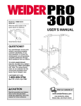
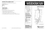
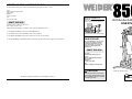
ORDERING REPLACEMENT PARTS
To order replacement parts, contact the ICON Fitness Lifestyle Ltd. office, or write:
Unit 4
Revie Road Industrial Estate
Revie Road
Beeston
Leeds, LS118JG
UK
Model No. WEEMSY87010
Serial No.
Tel: Country Code:
Write the serial number in the
space above for future reference.
08457 089 009
Outside the UK: 0 (044) 113 387 7133
Fax: 0 (044) 113 387 7125
USER'S MANUAL
Please provide the following information when ordering replacement parts:
1. The MODEL NUMBER of the product (WEEMSY87010).
2. The NAME of the product (WEIDER® 8507 Training System).
Serial Number Decal (Under Seat)
3. The SERIAL NUMBER of the product (see the front cover of this manual).
4. The KEY NUMBER and DESCRIPTION of the part(s) (see the PART LIST on page 22 of this manual).
QUESTIONS?
As a manufacturer, we are committed to providing complete
customer satisfaction. If you
have questions, or if there are
missing or damaged parts,
please call:
08457 089 009
Or write:
ICON Health & Fitness Ltd.
Unit 4
Revie Road Industrial Estate
Revie Road
Beeston
Leeds, LS11 8JG
UK
email: [email protected]
CAUTION
WEIDER is a registered trademark of ICON Health & Fitness, Inc.
Part No. 175452 R0901A
Printed in Canada © 2001 ICON Health & Fitness, Inc.
Read all precautions and instructions in this manual before using
this equipment. Save this manual
for future reference.
Class HC Fitness Product
Visit our website at
www.weiderfitness.com
EXPLODED DRAWING—Model No. WEEMSY87010
TABLE OF CONTENTS
11 8
IMPORTANT PRECAUTIONS . . . . . . . . . . . . . . . . . . . . . . . . . . . . . . . . . . . . . . . . . . . . . . . . . . . . . . . . . . . . . .2
BEFORE YOU BEGIN . . . . . . . . . . . . . . . . . . . . . . . . . . . . . . . . . . . . . . . . . . . . . . . . . . . . . . . . . . . . . . . . . . .3
ASSEMBLY . . . . . . . . . . . . . . . . . . . . . . . . . . . . . . . . . . . . . . . . . . . . . . . . . . . . . . . . . . . . . . . . . . . . . . . . . . .4
ADJUSTMENT . . . . . . . . . . . . . . . . . . . . . . . . . . . . . . . . . . . . . . . . . . . . . . . . . . . . . . . . . . . . . . . . . . . . . . . .16
TROUBLE-SHOOTING AND MAINTENANCE . . . . . . . . . . . . . . . . . . . . . . . . . . . . . . . . . . . . . . . . . . . . . . . . .19
CABLE DIAGRAMS . . . . . . . . . . . . . . . . . . . . . . . . . . . . . . . . . . . . . . . . . . . . . . . . . . . . . . . . . . . . . . . . . . . .20
PART LIST . . . . . . . . . . . . . . . . . . . . . . . . . . . . . . . . . . . . . . . . . . . . . . . . . . . . . . . . . . . . . . . . . . . . . . . . . . .22
EXPLODED DRAWING . . . . . . . . . . . . . . . . . . . . . . . . . . . . . . . . . . . . . . . . . . . . . . . . . . . . . . . . . . . . . . . . . .23
ORDERING REPLACEMENT PARTS . . . . . . . . . . . . . . . . . . . . . . . . . . . . . . . . . . . . . . . . . . . . . . . .Back Cover
15
5
31
82
17
50
76
32
15
69
6
59
68 81
27 67
60
65
2
48
2 66
74
70
8
78
15
75
21
77
12
45
8
44
81
12
45
41
24
85
43 10
80
11. Always disconnect the lat bar from the training system when performing an exercise that
does not use the lat bar.
84
12
3
8
65
39
42
5. Keep children under 12 and pets away from
the training system at all times.
12. Always lock the weight stack when the training system is not in use.
6. Never release the arms, leg lever, lat bar, or
nylon strap while weights are raised. The
weights will fall with great force.
WARNING: Before beginning this or any exercise program, consult your physician. This
is especially important for persons over the age of 35 or persons with pre-existing health problems.
Read all instructions before using. ICON assumes no responsibility for personal injury or property
damage sustained by or through the use of this product.
26
3
71
40
38
87
3
37
8
9
3
3
14
8
23
30
36
28
3
10
20
7
88
1
34
4
32
18
22
33
30
34
29
62
88
30
8
19
34
1
2
34
15 16
5
88
83
13
11
88
25
14. The training system is intended for home use
only. Do not use the training system in any
commercial, rental, or institutional
setting.
8. Always stand on the foot plate when per-
8
65
13. If you feel pain or dizziness at any time while
exercising, stop immediately and begin cooling down.
7. Keep hands and feet away from moving
parts. Always wear athletic shoes for foot
protection.
33
33
79
4. Inspect and tighten all parts often. Replace
any worn parts immediately.
51
44
51
47
35
3
10. Make sure that the cables remain on the pulleys at all times. If the cables bind while you
are exercising, stop immediately and make
sure that the cables are on all of the pulleys.
3. Use the training system only on a level surface. Place a mat beneath the training system to protect the floor or carpet.
8
49
12
47
3
49
8
3
57
8
61
23
9. The training system is intended for use by
only one person at a time; the maximum user
weight is 115 kg (250 lbs.).
2. Read all instructions in this manual and in
the accompanying literature before using the
training system.
48
3
55 9 70
46
3
64
24
3
3
5
forming an exercise that could cause the
training system to tip.
63
3
tions before using the training system.
1. It is the responsibility of the owner to ensure
that all users of the training system are adequately informed of all precautions.
54
15
48
54
8
55
11
72
WARNING: To reduce the risk of serious injury, read the following important precau-
9
53
73
78
46
86
59 56
58
IMPORTANT PRECAUTIONS
3
44
5
66
3
53
21
48 56
44
44
15
9
Note: A PART IDENTIFICATION CHART is attached to the centre of this manual. Remove the PART IDENTIFICATION CHART before beginning assembly.
89
21
33
58
89
27
70
8
5
52
21
9
48
R0901A
27
23
30
32
3
28
PART LIST—Model No. WEEMSY87010
Key No. Qty.
1
2
3
4
5
6
7
8
9
10
11
12
13
14
15
16
17
18
19
20
21
22
23
24
25
26
27
28
29
30
31
32
33
34
35
36
37
38
39
40
41
42
43
44
45
4
2
21
1
7
1
1
16
5
4
5
4
1
1
5
1
1
2
2
1
4
1
1
2
6
1
3
2
1
4
4
4
5
4
1
1
1
1
1
1
1
1
2
6
2
Description
Key No.
46
47
48
49
50
51
52
53
54
55
56
57
58
59
60
61
62
63
64
65
66
67
68
69
70
71
72
73
74
75
76
77
78
79
80
81
82
83
84
85
86
87
88
89
#
5/16” x 2 1/2” Carriage Bolt
5/16” Nylon Jam Nut
5/16” Nylon Locknut
Base
3/8” Nylon Jam Nut
Support Plate
1/4” Nylon Locknut
5/16” Washer
3/8” Washer
1/4” Washer
5/16” x 2 3/4” Bolt
Handgrip
Seat
5/16” x 2 3/4” Carriage Bolt
3 1/2” Pulley
3/8” x 3 1/2” Bolt
5/16” x 3” Bolt
1/4” x 3/4” Screw
Weight Bumper
1/4” x 2” Screw
3/8” Nylon Locknut
1” Metal Spacer
Short Cable
5/16” x 1 1/2” Bolt
Weight
Weight Pin
2” Square Inner Cap
Pad Tube
Leg Lever
Pad
1/4” x 1/2” Screw
1 1/2” Square Inner Cap
5/16” x 2 1/4” Bolt
3/4” Round Inner Cap
5/16” x 3 1/4” Bolt
Seat Frame
Seat Plate
1/4” x 2” Carriage Bolt
Nylon Strap
Seat Knob
Backrest
Front Upright
1/4” x 2 1/2” Screw
1 3/4” Square Inner Cap
7 3/4” Pad
Qty.
2
2
6
2
1
2
1
2
4
2
2
1
2
2
2
1
1
1
1
6
1
1
2
1
3
1
2
2
1
1
1
1
2
1
1
2
1
2
1
1
4
1
4
2
1
R0901A
Description
Arm
7” Handle
3/8” x 1 3/4” Bolt
1” Round Inner Cap
3/8” x 2 1/4” Bolt
1/2” x 3/8” Spacer
Arm Frame
Plastic Bushing
1” Retainer
1” Round Cover Cap
Large “U” Bracket
1 1/4” Square Inner Cap
Swivel Bracket
Cable Trap
4 1/2” “L” Pin
5/16” x 2” Bolt
5/16” x 2” Eyebolt
Stop Bracket
1” Plastic Stop
1/2” x 1/2” Spacer
Long Cable
Top Frame
Arm Frame Bushing
Arm Frame Bracket
3/8” x 2 3/4” Bolt
Stabiliser
Weight Guide
1/2” x 3/4” Spacer
5/16” x 6” Bolt
Adjustment “U” Bracket
“V” Pulley
Top Weight
“I”-Plate
Weight Tube Bumper
Weight Tube
4 1/2” Pulley
Large Cable Trap
Cable Clip
Chain
Lat Bar
1/4” Nylon Jam Nut
5/16” x 3 1/2” Bolt
2” Square Outer Cap
Round Inner Cap
User’s Manual
Note: “#” indicates a non-illustrated part. Specifications are subject to change without notice. See the back cover
of the user’s manual for information about ordering replacement parts.
22
BEFORE YOU BEGIN
System. If you have additional questions, please call
our Customer Service Department at 08457 089 009.
To help us assist you, please note the product model
number and serial number before calling. The model
number is WEEMSY87010. The serial number can be
found on a decal attached to the WEIDER 8507 (see
the front cover of this manual).
Thank you for selecting the versatile WEIDER® 8507
Training System. The WEIDER® 8507 offers an
impressive array of weight stations designed to develop every major muscle group of the body. Whether
your goal is to tone your body, build dramatic muscle
size and strength, or improve your cardiovascular system, the WEIDER® 8507 will help you to achieve the
specific results you want.
Before reading further, please review the drawing
below and familiarise yourself with the parts that are
labelled.
For your safety and benefit, read this manual carefully before using the WEIDER® 8507 Training
ASSEMBLED DIMENSIONS:
Height: 196 cm (77 in.)
Width: 99 cm (39 in.)
Length: 122 cm (48 in.)
High Pulley Station
Lat Bar
Arms
Backrest
Leg Lever
Weight Stack
Low Pulley Station
Weight Pin
Foot Plate
3
ASSEMBLY
NOTES
Assembly requires two people. Due to the size
and weight of the training system, assemble it in the
location where it will be used.
• Tighten all parts as you attach them, unless
instructed to do otherwise.
THE FOLLOWING TOOLS (NOT INCLUDED) ARE
REQUIRED FOR ASSEMBLY:
• Place all parts of the training system in a cleared
area and remove the packing materials; do not
dispose of the packing materials until assembly is
completed.
• two (2) adjustable wrenches
• one (1) phillips screwdriver
• Before beginning, read each assembly step and
look at each drawing carefully.
• one (1) rubber mallet
• For help identifying small parts used in assembly,
refer to the PART IDENTIFICATION CHART
attached to the centre of this manual.
• lubricant, such as grease or petroleum jelly,
and soapy water are also required.
To simplify assembly, the following tools are recommended: a socket set, open or closed wrenches, or
ratchet wrenches.
• During assembly, be sure that all parts are oriented as shown in the drawings.
1. Before you begin, make sure that you have
carefully read the instructions at the top of
this page.
1
88
3
Press a 2” Square Outer Cap (88) onto each end
of the Stabiliser (71). Press a 2” Square Outer
Cap onto each side of the Base (4). Press a 2”
Square Inner Cap (27) into the end of the Base.
71
88
88
4
1
88
Insert two 5/16” x 2 1/2” Carriage Bolts (1) up
through the Stabiliser (71). Insert two 5/16” x
2 1/2” Carriage Bolts up through the Base (4).
1
Slide the indicated end of the Base (4) onto the
5/16” x 2 1/2” Carriage Bolts (1) in the Stabiliser
(71). Tighten a 5/16” Nylon Locknut (3) onto each
Carriage Bolt.
27
2
72
2. Set two Weight Bumpers (19) on the Base (4) as
shown.
19
Insert the Weight Guides (72) into the Weight
Bumpers (19) and the Base (4). Attach each
Weight Guide to the Base with a 5/16” x 2 3/4”
Bolt (11), two 5/16” Washers (8), two 1/2” x 1/2”
Spacers (65), and a 5/16” Nylon Locknut (3).
3
8
65
8
8
4
65
11
4
21
3. Slide six Weights (25) onto the Weight Guides (72).
Be sure that all of the Weights are turned so the pin
grooves are on the indicated side.
CABLE DIAGRAMS
3
The cable diagrams below show the proper routing of the Short Cable (23) and the Long Cable (66). Use the
diagrams to make sure that the two cables are assembled correctly. The numbers show the routing of each cable.
Long Cable (66)
2
4
Top Frame
8
Short Cable (23)
2
72
High Pulley
1
25
5*
Pin Grooves
3
6*
7*
Weight Stack—1
4. Press the 1 1/4” Square Inner Cap (57) into the
Front Upright (42).
4
64
3
Low Pulley—3
Attach the 1” Plastic Stop (64) to the centre hole in
the Stop Bracket (63) with a 5/16” x 1 1/2” Bolt (24)
and 5/16” Nylon Locknut (3).
63
24
8
57
Attach the Stop Bracket (63) to the Front Upright
(42) with a 5/16” x 2” Bolt (61), 5/16” Washer (8),
and 5/16” Nylon Locknut (3).
61
Slide the Front Upright (42) onto the two 5/16” x
2 1/2” Carriage Bolts (1) in the Base (4). Thread
two 5/16” Nylon Locknuts (3) onto the Carriage
Bolts. Do not tighten the Nylon Locknuts yet.
42
3
1
4
20
5
5. Press the Weight Tube Bumper (79) into the end of
the Weight Tube (80). Slide the Top Weight (77)
onto the Weight Tube. Be sure that the pins on the
Weight Tube are resting in the pin grooves under
the Top Weight.
5
TROUBLE-SHOOTING AND MAINTENANCE
Inspect and tighten all parts each time you use the training system. Replace any worn parts immediately. The
training system can be cleaned using a damp cloth and mild non-abrasive detergent. Do not use solvents.
Locate the Short Cable (23). Attach the Short
Cable to the Weight Tube (80) with a 5/16” x 1 1/2”
Bolt (24) and a 5/16” Nylon Locknut (3).
TIGHTENING THE CABLES
15
23
Woven cable, the type of cable used on the training
system, can stretch slightly when it is first used. If there
is slack in the cables before resistance is felt, the
cables should be tightened. Locate the adjustment
sleeve and adjustment screw near the lower end of the
Short Cable (23). Loosen the adjustment screw. Pull
the end of the Short Cable until there is no slack. Slide
the adjustment sleeve and the ball against the indicated 3 1/2” Pulley (15). Retighten the adjustment screw.
Make sure that the cables are not too tight, or the top
weight will be lifted off the weight stack.
77
3
24
80
Pins
Ball
Adjustment
Sleeve
23
79
6. Lubricate the insides of the holes in the Top Weight
(77). Slide the Top Weight onto the stack of
Weights (25).
6
77
Lubricate
25
7. Press two 2” Square Inner Caps (27) into the Top
Frame (67).
7
Attach the Top Frame (67) to the Front Upright (42)
with two 5/16” x 2 3/4” Bolts (11), the Support Plate
(6), and two 5/16” Nylon Locknuts (3). Do not tighten the Nylon Locknuts yet.
11
11
6
67
8
27
27
Attach the Top Frame (67) to the Stop Bracket (63)
with a 5/16” x 2 3/4” Bolt (11), 5/16” Washer (8),
and 5/16” Nylon Locknut (3). Do not tighten the
Nylon Locknut yet.
3
63
3
42
6
Adjustment
Screw
19
ATTACHING THE LAT BAR OR NYLON STRAP TO
THE LOW PULLEY STATION
8. Attach the upper ends of the Weight Guides (72) to
the Top Frame (67) with the 5/16” x 6” Bolt (74), two
1/2” x 3/4” Spacers (73), and a 5/16” Nylon Locknut
(3).
23
Attach the Lat Bar (85) to the Short Cable (23) with a
Cable Clip (83). For some exercises, the Chain (84)
should be attached between the Lat Bar and the Short
Cable with two Cable Clips. Adjust the length of the
Chain between the Lat Bar and the Short Cable so
the Lat Bar is in the correct starting position for
the exercise to be performed.
83
84
8
73
3
67
Tighten all Nylon Locknuts used in steps 4
through 8.
83
74
85
The Nylon Strap (39) can be attached in the same
manner.
72
39
9. Press two 1 3/4” Square Inner Caps (44), two 1 1/2”
Square Inner Caps (32), and two Round Inner Caps
(89) into the Arm Frame (52).
9
32
52
89
44
10. Lubricate the upper axle on the Arm Frame (52).
Hold the axle between the two Arm Frame
Bushings (68). Set the Arm Frame Bushings and
the Arm Frame on the welded plate on the Top
Frame (67). Make sure that the Arm Frame is
turned so the bracket is on the side shown.
Place the Arm Frame Bracket (69) over the Arm
Frame Bushings. Attach the Arm Frame Bracket to
the Top Frame with four 1/4” x 1/2” Screws (31) and
1/4” Nylon Jam Nuts (86).
10
31
68
69
Lubricate
52
67
86
18
7
Bracket
11. Press a 1 3/4” Square Inner Cap (44) into each end
of an Arm (46).
ATTACHING AND REMOVING THE SEAT
11
36
Set the bracket on the Seat Frame (36) on the indicated
pin on the Front Upright (42). Attach the Seat Frame to
the Front Upright with the 5/16” x 2 3/4” Carriage Bolt
(14) and Seat Knob (40).
Apply lubricant to the lower axles on the Arm Frame
(52). Slide an Arm (46) onto one of the axles. Hold
two 1” Retainers (54) and a 1” Round Cover Cap
(55) against the lower end of the axle. The teeth
on the Retainers must bend toward the Round
Cover Cap (see the inset drawing). Tap the
Retainers and Round Cover Cap onto the axle.
52
For some exercises, the Seat (13) must be removed.
First, make sure that the chain is not attached to the leg
lever. Next, remove the Seat Knob (40) and 5/16” x
2.3/4” Carriage Bolt (14) from the Seat Frame (36). Lift
the Seat Frame off the Front Upright (42).
Lubricate Axle
Bracket
Assemble the other Arm (46) to the Arm Frame (52)
in the same manner.
44
40
14
Pin
42
54
ATTACHING THE LEG LEVER TO THE LOW
PULLEY STATION
55
To use the Leg Lever (29), the seat must be attached to
the front upright (see ATTACHING AND REMOVING
THE SEAT above). Attach the Chain (84) between the
Short Cable (23) and the 5/16” x 2” Eyebolt (62) on the
Leg Lever with two Cable Clips (83).
44
46
Axle
54
84
29
55
83
12. Insert the two 4 1/2” “L” Pins (60) down through the
indicated holes in the Arm Frame (52) and the Arms
(46).
12
23
62
60
52
ATTACHING THE LAT BAR OR NYLON STRAP TO
THE HIGH PULLEY STATION
Attach the Lat Bar (85) to the Long Cable (66) with a
Cable Clip (83). For some exercises, the Chain (84)
should be attached between the Lat Bar and the Long
Cable with two Cable Clips. Adjust the length of the
Chain between the Lat Bar and the Long Cable so
the Lat Bar is in the correct starting position for the
exercise to be performed.
46
13. Wet both Arms (46) with soapy water. Slide a 7 3/4”
Pad (45) onto each Arm.
13
Slide a Handgrip (12) into the indicated end of a 7”
Handle (47). Insert the Handle into one of the Arms
(46). Attach the Handle with a 5/16” x 2.1/4” Bolt
(33), two 5/16” Washers (8), a 1/2” x 3/8” Spacer
(51), and a 5/16” Nylon Locknut (3).
46
85
The Nylon Strap (39) can be attached in the same
manner.
8
8
39
49
Attach a 7” Handle (47) to the other Arm (46) in the
same manner.
45
51
33
45
47
8
84
12
47
3
46
83
66
17
ADJUSTMENT
The instructions below describe how each part of the training system can be adjusted. IMPORTANT: When
attaching the lat bar or nylon strap, make sure that the attachments are in the correct starting position
for the exercise to be performed. If there is any slack in the cable or chain as an exercise is performed,
the effectiveness of the exercise will be reduced.
14. Attach a Large “U” Bracket (56) to one of the Arms
(46) with a 3/8” x 2 3/4” Bolt (70), 3/8” Washer (9),
and 3/8” Nylon Locknut (21). Be sure that the
Swivel Bracket (58) is on the inside as shown.
Do not overtighten the 3/8” Nylon Locknut.
14
58
21
56
Attach a Large “U” Bracket (56) to the other Arm
(46) in the same manner.
21
46
9
CHANGING THE WEIGHT SETTING
9
70
46
25
26
15. IMPORTANT: As you assemble the Long Cable
(66) and the Short Cable (23), refer to the CABLE
DIAGRAMS on page 20 of this manual to make
sure that the Cables are properly routed.
SWITCHING THE ARMS TO THE PRESS MODE OR
THE BUTTERFLY MODE
To perform the BENCH PRESS exercise, switch the
Arms (46) to the press mode by inserting the two 4 1/2”
“L” Pins (60) down through the indicated holes in the
Arm Frame (52) and the Arms.
15
60
21
9
70
9
67
66
Lay the Long Cable (66) over a 4 1/2” Pulley (81).
Attach the Pulley inside the Top Frame (67) with a
3/8” x 2 3/4” Bolt (70), two 3/8” Washers (9), the two
1/2” x 1/2” Spacers (65), and a 3/8” Nylon Locknut
(21).
46
23
16
65
81
Find the end of the Long Cable (66) that does not
have a rubber ball. Insert that end of the Long
Cable up through the indicated opening in the Top
Frame (67).
52
To perform the BUTTERFLY exercise, switch the Arms
(46) to the butterfly mode by inserting one of the 4 1/2”
“L” Pins (60) down through the hole in the centre of the
Arm Frame (52) and the Stop Bracket (not shown). Set
the other “L” Pin aside.
70
56
To change the weight setting, insert the Weight Pin (26)
under one of the Weights (25). Make sure to insert the
Weight Pin until the bent end of the Weight Pin is touching the Weights, and turn the bent end downward. The
weight setting can be changed from 6 lbs. to 81 lbs., in
increments of 12.5 lbs. (1 kg = 2.2 lbs.). Note: Due to
the cables and pulleys, the actual amount of resistance at each exercise station will vary from the
weight setting.
9
16. Remove the 3/8” x 1 3/4” Bolt (48), 3/8” Nylon Jam
Nut (5), and 3 1/2” Pulley (15) from the indicated
bracket on the Top Frame (67). Insert the end of the
Long Cable (66) through the bracket and down
through the indicated hole.
16
29. Slide a Handgrip (12) onto each end of the Lat
Bar (85).
15
5
66
67
29
12
Hole
85
Re-attach the 3 1/2” Pulley (15) to the bracket on
the Top Frame (67) with the 3/8” x 1 3/4” Bolt (48)
and 3/8” Nylon Jam Nut (5). Be sure that the Long
Cable is between the Pulley and the top of the
bracket.
17. Wrap the Long Cable (66) around the “V” Pulley
(76). Attach the Pulley and a Large Cable Trap (82)
to the welded bracket on the Top Frame (67) with a
3/8” x 2 1/4” Bolt (50) and 3/8” Nylon Jam Nut (5).
Be sure that the Large Cable Trap is turned to
the indicated position.
48
12
17
67
5 76
82
50
30. Make sure that all parts are properly tightened. The use of all remaining parts will be explained in ADJUSTMENT, beginning on page 16 of this manual. Before using the training system, pull each cable a few times
to make sure that the cable moves smoothly over the pulleys. If one of the cables does not move smoothly,
locate and correct the problem before using the training system. IMPORTANT: If the cables are not properly routed, they may be damaged when heavy weight is used. See the CABLE DIAGRAMS on page 20
of this manual.
66
18. Note: The 3 1/2” Pulley (15) used in this step is
pre-assembled. It is shown removed for easier
part identification.
18
Remove the 3/8” x 1 3/4” Bolt (48), the 3/8” Nylon
Jam Nut (5), Cable Trap (59), and the 3.1/2” Pulley
(15) from the Swivel Bracket (58) on the left Arm
(46).
Wrap the Long Cable (66) around the 3 1/2” Pulley
(15). Re-attach the Pulley to the Swivel Bracket
(58) with the 3/8” Nylon Jam Nut (5) and 3/8” x 1
3/4” Bolt (48).
66 15
48
58
59
5
46
Be sure that the Cable Trap (59) is oriented as
shown.
10
15
26. Press a 1 1/2” Square Inner Cap (32) into the Leg
Lever (29).
19. Note: The 4 1/2” Pulley (81) shown in this step
is pre-attached to the Adjustment “U” Bracket
(75).
26
Attach the 5/16” x 2” Eyebolt (62) to the Leg Lever
(29) with a 5/16” Washer (8) and a 5/16” Nylon
Locknut (3).
3
Remove the 3/8” x 1 3/4” Bolt (48), 3/8” Nylon Lock
Nut (21), and the 4 1/2” Pulley (81) from the
Adjustment “U” Bracket (75).
29
Attach the Adjustment “U” Bracket (75) to the Front
Upright (42) with the 5/16” x 3 1/4” Bolt (35), a 5/16”
Washer (8), and a 5/16” Nylon Locknut (3). Thread
the Nylon Locknut onto the Bolt until the first
two threads of the Bolt are through the Nylon
Locknut.
36
Lubricate a 5/16” x 2 1/4” Bolt (33). Attach the Leg
Lever (29) to the Seat Frame (36) with the Bolt and
a 5/16” Nylon Locknut (3). Do not overtighten the
Nylon Locknut; the Leg Lever must be able to
pivot freely.
33
8
62
3
32
27. Set the bracket on the Seat Frame (36) onto the
indicated pin on the Front Upright (42). Attach the
Seat Frame with a 5/16” x 2 3/4” Carriage Bolt (14)
and the Seat Knob (40).
19
48
35
3
27
36
Wrap the Long Cable (66) around the 4 1/2” Pulley
(81) as shown. Re-attach the Pulley to the
Adjustment “U” Bracket (75) with the 3/8” x 1 3/4”
Bolt (48) and 3/8” Nylon Locknut (21).
40
8
75
81
21 66
14
42
Pin
42
28. Press 3/4” Round Inner Caps (34) into the ends of
a Pad Tube (28). Insert the Pad Tube into the Seat
Frame (36). Slide a Pad (30) onto each end of the
Pad Tube.
20. Note: The 3 1/2” Pulley (15) used in this step is
pre-assembled. It is shown removed for easier
part identification.
28
20
Wrap the Long Cable (66) around the 3.1/2” Pulley
(15) on the right Arm (46). Tighten the 3/8” Nylon
Jam Nut (5) and 3/8” x 1 3/4” Bolt (48). Be sure
that the Cable Trap (59) is oriented as shown.
Press 3/4” Round Inner Caps (34) into the ends of
the other Pad Tube (28). Insert the Pad Tube into
the Leg Lever (29). Slide a Pad (30) onto each end
of the Pad Tube.
66
48
58
15
5
59
36
30
34
28
30
34
14
29
11
46
21. Attach the 5/16” x 3” Bolt (17), two 5/16” Washers
(8), and a 5/16” Nylon Jam Nut (2) to the indicated
hole in the Top Frame (67).
21
8
23. Attach the 5/16” x 3 1/2” Bolt (87), two 5/16”
Washers (8), the 1” Metal Spacer (22), and a 5/16”
Nylon Locknut (3) to the Front Upright as shown.
17
67
Slide the end of the Long Cable (66) onto the 5/16”
x 3” Bolt (17). Tighten another 5/16” Nylon Jam Nut
(2) onto the Bolt. Note: The 5/16” Nylon Jam Nut
should not be fully tightened against the end of
the Cable. There must be enough room between
the Nylon Jam Nuts for the end of the Cable to
pivot.
23
Wrap the Short Cable (23) around a 3 1/2” Pulley
(15). Attach the Pulley to the Front Upright (42) with
a 3/8” x 3 1/2” Bolt (16), a 3/8” Washer (9), and a
3/8” Nylon Jam Nut (5). Be sure that the Short
Cable is between the Pulley and the Metal
Spacer.
2
66
22. See the inset drawing. Assemble the two “I” Plates
(78), two 3 1/2” Pulleys (15), the Long Cable (66),
and the Short Cable (23) with the two 3/8” x 1 3/4”
Bolts (48) and two 3/8” Nylon Jam Nuts (5) as
shown.
87
42
8
22
9
23
5
3
24. Attach the Backrest (41) to the Front Upright (42)
with two 1/4” x 2 1/2” Screws (43) and 1/4”
Washers (10).
16
15
8
24
22
10
43
41
42
25. Press a 1 1/2” Square Inner Cap (32) into the Seat
Frame (36).
66
15
78
48
78
25
13
Insert a 1/4” x 2” Carriage Bolt (38) into the centre
hole in the Seat Plate (37). Attach the Seat Plate to
the narrow end of the Seat (13) with two 1/4” x 3/4”
Screws (18).
Insert the 1/4” x 2” Carriage Bolt (38) into the indicated hole in the Seat Frame (36). Tighten a 1/4”
Nylon Locknut (7) with a 1/4” Washer (10) onto the
Carriage Bolt.
5
37
38
32
18
15
23
12
10
Attach the other end of the Seat (13) to the Seat
Frame (36) with a 1/4” Washer (10) and the 1/4” x
2” Screw (20).
20
13
7
36
3/4" Round Inner Cap (34)
REMOVE THIS PART IDENTIFICATION
CHART FROM THE MANUAL
1" Round Inner Cap (49)
1" Round Cover Cap (55)
This chart is provided to help you identify the small parts used in assembly. Important: Some parts may have
been pre-assembled for shipping purposes. If you cannot find a part in the parts bags, check to see if it
has been pre-assembled.
5/16" x 2" Eyebolt (62)
1 1/4" Square Inner Cap (57)
1 1/2" Square Inner Cap (32)
1 3/4" Square Inner Cap (44)
2" Square Inner Cap (27)
2" Square Outer Cap (88)
1/4" Nylon Locknut (7)
1/4" x 1/2" Screw (31)
5/16" x 2 1/2" Carriage Bolt (1)
1/2" x 3/8" Spacer (51)
1/4" Nylon Jam Nut (86)
1/4" x 3/4" Screw (18)
5/16" x 2 3/4" Carriage Bolt (14)
1/2" x 1/2" Spacer (65)
5/16" Nylon Jam Nut (2)
5/16" x 2 3/4" Bolt (11)
5/16" Nylon Locknut (3)
1/4" x 2 1/2" Screw (43)
1/2" x 3/4" Spacer (73)
3/8" x 2 3/4" Bolt (70)
3/8" Nylon Jam Nut (5)
5/16" x 1 1/2" Bolt (24)
1" Metal Spacer (22)
5/16" x 3" Bolt (17)
3/8" Nylon Locknut (21)
5/16" x 2" Bolt (61)
1" Plastic Stop (64)
5/16" x 3 1/4" Bolt (35)
1/4" Washer (10)
5/16" x 2 1/4" Bolt (33)
5/16" x 3 1/2" Bolt (87)
5/16" Washer (8)
3/8" x 1 3/4" Bolt (48)
3/8" x 2 1/4" Bolt (50)
1" Retainer (54)
3/8" x 3 1/2" Bolt (16)
3/8" Washer (9)
1/4" x 2" Carriage Bolt (38)
5/16" x 6" Bolt (74)