1
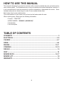
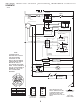
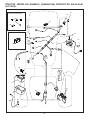
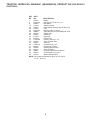
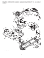
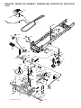
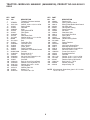
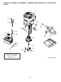
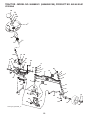
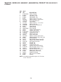
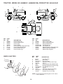
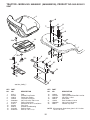
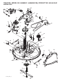
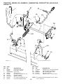
5000
96048000100
Repair Parts Manual
435060
HOW TO USE THIS MANUAL
This manual is designed to provide the customer with a means to identify the parts on his/her tractor
when ordering parts. The illustrations may or may not represent the actual assemblies; therefore, it
is not recommended to use this manual as a guide to assemble or disassemble the tractor. Some
hardware and parts are drawn larger in order to more readily identify them.
Each tractor has its own model number.
The model number for your tractor can be found on the fender under the seat.
When ordering parts, always give the following information:
• Product - “TRACTOR”
• MODEL NUMBER - “960480001 (96048000100)”
• Part Number
• Part Description
TABLE OF CONTENTS
SCHEMATIC ................................................................................................................ 3
ELECTRICAL ............................................................................................................4-5
CHASSIS ..................................................................................................................6-7
DRIVE........................................................................................................................8-9
ENGINE .................................................................................................................10-11
STEERING ............................................................................................................12-13
DECALS ..................................................................................................................... 14
SEAT .......................................................................................................................... 15
MOWER DECK .....................................................................................................16-17
MOWER LIFT ............................................................................................................. 18
WARRANTY............................................................................................................... 19
2
TRACTOR - MODEL NO. 960480001 (96048000100), PRODUCT NO. 960 48 00-01
SCHEMATIC
SCH18
BATTERY
RED
SOLENOID
STARTER
M
RED
A
FUSE
AMMETER
(OPTIONAL)
BLACK
WHITE
S
B
G
WHITE
M
A1
L
A2
ATTACHMENT CLUTCH
(CLUTCH OFF)
BLACK
CLUTCH/BRAKE
(PEDAL UP)
GRAY
REVERSE SWITCH
(NOT IN REVERSE)
BLACK
BLACK
BLACK
2
BLACK
3
BLACK
BLACK
BLACK
BLACK
1
6
SEAT SWITCH
(NOT OCCUPIED)
GRAY
SHORTING
CONNECTOR
CHASSIS
HARNESS
IGNITION
UNIT
(OPTIONAL)
SPARK
PLUGS GAP
(2 PLUGS ON
TWIN CYL. ENGINES)
HOUR
METER
BLUE
BLACK
NOTE
YOUR TRACTOR IS
EQUIPPED WITH A SPECIAL
ALTERNATOR SYSTEM.
THE LIGHTS ARE NOT
CONNECTED TO THE
BATTERY, BUT HAVE THEIR
OWN ELECTRICAL SOURCE.
BECAUSE OF THIS, THE
BRIGHTNESS OF THE LIGHTS
WILL CHANGE WITH ENGINE
SPEED. AT IDLE THE LIGHTS
WILL DIM. AS THE ENGINE IS
SPEEDED UP, THE LIGHTS
WILL BECOME THEIR
BRIGHTEST.
BLACK /WHITE
JUNCTION
CONNECTOR
BLACK
FUEL
LINE
12V
POWER OUTLET
(OPTIONAL)
BLUE
FUEL SHUT-OFF
SOLENOID
(IF SO EQUIPPED)
CHARGING SYSTEM OUTPUT
3 AMP DC @ 3600 RPM
28 VOLTS AC MIN. @ 3600 RPM
(CHARGING SYSTEM DISCONNECTED)
RED
DIODE
ALTERNATOR
IGNITION SWITCH
POSITION
CIRCUIT
OFF
RUN/OVERRIDE
M+G+A1
B+A1
RUN
START
B+A1
B + S + A1
“MAKE”
L+A2
3
6
6
3
2
1
2
5
5
1
4
4
CHASSIS HARNESS
CONNECTOR
(MATING SIDE)
DASH HARNESS
CONNECTOR
(MATING SIDE)
3
WIRING INSULATED CLIPS
NOTE: IF WIRING INSULATED
CLIPS WERE REMOVED FOR
SERVICING OF UNIT, THEY
SHOULD BE RE-INSTALLED TO
PROPERLY SECURE YOUR
WIRING.
NON-REMOVABLE
CONNECTIONS
REMOVABLE
CONNECTIONS
TRACTOR - MODEL NO. 960480001 (96048000100), PRODUCT NO. 960 48 00-01
ELECTRICAL
T31K
33
With 12V Outlet Option
30
103
87
59
With Service Minder Option
27
43
42
46
41
40
26
25
16
71
90
2
94
29
28
55
92
93
4
TRACTOR - MODEL NO. 960480001 (96048000100), PRODUCT NO. 960 48 00-01
ELECTRICAL
KEY
NO.
PART
NO.
DESCRIPTION
1
2
8
16
25
26
27
28
29
30
33
40
41
42
43
55
71
87
90
92
93
94
144924
74760412
193228
176138
412894
175158
73510400
198885
192749
193350
411935
401098
17720408
131563
192507
17060512
400449
197802
400725
196615
192540
191834
Battery
Bolt Hex Hd 1/4-20 unc x 3/4
Box Battery
Switch Interlock
Cable Starter Battery 6 Ga. BL/Red 14.5
Fuse
Nut Keps Hex 1/4-20 unc
Cable Ground 18" Rear Battery Blk 6 Ga.
Switch Seat
Switch Ign
Key/Chain
Harness Ign
Screw 1/4-20 unc x 1/2
Cover Terminal Red
Solenoid
Screw 5/16-18 x 3/4
Harness Ign. Chass.
Switch Interlock Clutch
Cover Terminal
Harness Pigtail Reverse Switch
Screw Plastic 10-14 x 2.0
Modual Reverse ROS
NOTE: All component dimensions given in U.S. inches
1 inch = 25.4 mm
5
TRACTOR - MODEL NO. 960480001 (96048000100), PRODUCT NO. 960 48 00-01
CHASSIS
18
14
5
176
151
137
176
176
177
175
182
236
235
130
68
34
68
36
196
181
235
176
194
37
68
183
194
236
213
68
183
138
68
68
180
287
181
162
218
228
58
189
217
189
194
52
189
228
189
152
Chassis-tex_ALPHA_1
6
189
TRACTOR - MODEL NO. 960480001 (96048000100), PRODUCT NO. 960 48 00-01
CHASSIS
KEY
NO.
PART
NO.
DESCRIPTION
5
14
18
34
36
37
52
58
68
130
137
138
151
152
162
175
176
177
180
181
182
183
189
194
196
213
217
218
228
235
236
287
---
197783X428
187559X550
187566X428
196125
17060512
414872X550
73680500
412280
17490508
416358
184921
193224X428
187568
199535
142432
193243
400776
195228
414685
193102X428
193057
74520520
17000512
73900500
414579
74760512
409167
196395
195161
406129
73930500
17600406
193640X428
Dash
Hood
Grille
Plate Engine
Screw 5/16-18 x 3/4
Fender
Nut Lock 5/16-18
Drawbar Upper
Screw Thdrol 5/16-18 x 1/2
Screw #10 x 0.750
Bumper Hood
Cupholder
Bracket Pivot
Shield Browning/Debris
Screw Hex Wsh Hi-Lo 1/4 x 1/2
Crossmember
Screw 10-24 x 5/8 Wshd Qdrx
Bushing Steering
Chassis
Bushing Mtg. Fender Crgo.
Dash Lower
Bolt 5/16-18 x 1-1/4
Screw 5/16-18 x 3/4
Nut Lock Hex Flange 5/16-18
Console Asm. Deck Lift
Bolt 5/16-18 x 3/4
Rod Pivot Hood
X-Piece Hood Stop
Stud Fastener
Spacer Fender
Nut Center Lock 5/16-18
Screw 1/4-20 x 3/8
Plug Switch Light
NOTE: All component dimensions given in U.S. inches
1 inch = 25.4 mm
7
TRACTOR - MODEL NO. 960480001 (96048000100), PRODUCT NO. 960 48 00-01
DRIVE
70
74
56
185
221
184
172
35
125
172
160
42
125
167
186
160
189
49
203
187
188
64
50
190
51
161
155
139
202
52
165
140
61
141
157
116
51
166
192 23 176
134
174
233
232
192
195
125
178
158
2
193
22
17
15
26
73
2
1
29
175
116
166
183
73
37
205
33
drive-tex_peerless_fender_47
8
159
TRACTOR - MODEL NO. 960480001 (96048000100), PRODUCT NO. 960 48 00-01
DRIVE
KEY
NO.
1
2
15
17
22
23
26
29
33
35
37
42
49
50
51
52
56
61
64
70
73
74
116
125
134
139
140
141
155
157
158
159
PART
NO.
-----123583X
19131316
197297
197660
106933X
197455
197267
12000001
197722
121749X
8883R
72110614
194327
73900600
194326
138255
165999
196200
429581X428
74490544
142432
73900500
17000512
197857
74550412
10040400
19091210
12000028
105701X
194352
76020412
KEY
NO.
160
161
165
166
167
172
174
175
176
178
183
184
185
186
187
188
189
190
192
193
195
202
203
205
221
232
233
287
DESCRIPTION
Transaxle, Peerless 203-569
Key Square
Washer 13/32 x 13/16 x 16 Ga.
Spring, Brake
Rod Shift
Knob
Spring Brake RTN
Rod, Brake
Ring E
Rod, Brake, Park
Washer 25/32 x 1-1/4 x 16 Ga.
Cover, Foot Pedal
Bolt
Pulley Idler Flat
Lock Nut 3/8-16
Idler V-Groove
V-Belt, Drive
Pulley Transaxle
Shaft Asm. Pedal Brake Control
Console
Bolt 5/16-18 Gr. 5
Screw 1/4 x 1/2
Nut Lock Hex Flange 5/16-18
Screw 5/16-18 x 3/4
Arm Shift
Bolt 1/4-20 unf Gr. 8 w/Patch
Washer Lock Hvy Helical 1/4
Washer 9/32 x 3/4 x 10 Ga.
Ring Retainer
Washer Plate Shf
Keeper T/A
Pin Cotter 1/8 x 3/4
PART
NO.
169484
105709X
196212
429164
405257
197657
197289
197858
196214
197456
137057
198403X505
72110622
194321
19133210
194323
194317
194318
150360
17060512
197332
197859
19111116
121748X
403187
74780716
405296
421648
DESCRIPTION
Retainer Clip
Spring, Return, Clutch
Busing Shaft Brake Hand Control
Nut Push .625
Latch Brake Parking
Strap Torque LH
Nut Push
Shaft Asm Shift
Arm Clevis Rod Shift
Spring Shift
Spacer, Axle
Handle Parking Brake
Bolt
Spacer Retainer
Washer
Link Clutch Ground Drive
Bellcrank Ground Drive
Keeper Bellcrank Ground Drive
Nut Lock Center 1/4-28
Screw 5/16-18 x 3/4
Bracket Brake Rod
Link Shift
Washer 11/32 x 11/16 x 16 Ga.
Washer 25/32 x 1-5/8 x 16 Ga.
Retainer Spring Clip Handle
Bolt 7/16-14 x 1 Gr. 5
Washer Serrated
Keeper Pulley T/A
NOTE: All component dimensions given in U.S. inches
1 inch = 25.4 mm
9
TRACTOR - MODEL NO. 960480001 (96048000100), PRODUCT NO. 960 48 00-01
ENGINE
1
21
45
20
122
79
84
97
18
96
15
69
2
12
37
42
28
29
85
90
9
OPTIONAL EQUIPMENT
Spark Arrester
engine-tex_BS_30
10
TRACTOR - MODEL NO. 960480001 (96048000100), PRODUCT NO. 960 48 00-01
ENGINE
KEY PART
NO. NO.
1
-- ----
2
9
12
15
18
20
21
28
29
37
42
45
69
79
84
85
90
96
97
122
179758
194319
140186
407545
430220
170545
416358
401137
137180
123487
10040700
73510400
165291
192334
17060620
71170764
17000616
19091416
17670412
421922
DESCRIPTION
Engine Briggs Model No.
219807-0389-B1
Muffler
Keeper Belt Engine
Pulley Engine
Tank Fuel 1.5
Cap Asm. Fuel
Control Throttle
Screw #10 x 0.750
Fuel Line
Spark Arrester Kit
Clamp Hose
Washer Lock 7/16
Nut Keps Hex 1/4-20 unc
Gasket
Screw 5/16 - 18 x .75
Screw 3/8-16 x 1-1/4
Bolt Hex 7/16-20 x 4 Gr. 5
Screw 3/8-16 x 1
Washer 9/32 x 7/8 x 16 Ga.
Screw 1/4-20 x 3/4
Extension Drain Oil
NOTE: All component dimensions given in U.S. inches.
1 inch = 25.4 mm
For engine service and replacement parts, call the toll free
number for your engine manufacturer listed below:
Briggs & Stratton
1-800-233-3723
Engine Power Rating Information
The gross power rating for individual gas engine models is labeled in accordance with SAE (Society of Automotive
Engineers) code J1940 (Small Engine Power & Torque Rating Procedure), and rating performance has been obtained
and corrected in accordance with SAE J1995 (Revision 2002-05). Torque values are derived at 3060 RPM; horsepower
values are derived at 3600 RPM. Actual gross engine power will be lower and is affected by, among other things, ambient operating conditions and engine-to-engine variability. Given both the wide array of products on which engines are
placed and the variety of environmental issues applicable to operating the equipment, the gas engine will not develop
the rated gross power when used in a given piece of power equipment (actual “on-site” or net power). This difference is
due to a variety of factors including, but not limited to, accessories (air cleaner, exhaust, charging, cooling, carburetor,
fuel pump, etc.), application limitations, ambient operating conditions (temperature, humidity, altitude), and engine-toengine variability. Due to manufacturing and capacity limitations, Briggs & Stratton may substitute an engine of higher
rated power for this Series engine.
11
TRACTOR - MODEL NO. 960480001 (96048000100), PRODUCT NO. 960 48 00-01
STEERING
26
72
33
45
1
20
71
21
13
16
63
28
22
64
63
28
60
9
57
8
63
74
66
7
67
2
9
7
8
59
19
74
6
35
74
58
74
67
6
4
61
5
14
15
8
14
69
68
13
62
70
15
13
53
steering-tex_STDHRS_10
12
TRACTOR - MODEL NO. 960480001 (96048000100), PRODUCT NO. 960 48 00-01
STEERING
KEY
NO.
PART
NO.
DESCRIPTION
1
2
4
5
6
7
8
9
13
14
15
16
19
20
21
22
26
28
33
35
45
53
57
58
59
60
61
62
63
64
66
67
68
69
70
71
72
74
414803X428
418168
416845
416846
6266H
121748X
12000029
121232X
121749X
10040600
73540600
429374
194729
198375X428
186737
420537
414854X428
17000612
10040500
194732
19113812
188967
407465
194747
194748
73971000
194740
194741
17000512
199849
71020748
194737
73900700
199162
417065
190752
428982
3366R
Wheel, Steering
Axle Asm., Front
Spindle Asm., LH
Spindle Asm., RH
Washer Thrust 0.75 x 1.23
Washer 25/32 x 1-5/8 x 16 Ga.
Ring, Clip #T5304-75
Cap, Spindle
Washer 25/32 x 1-1/4 x 16 Ga.
Washer Lock 3/8
Nut, Crown Lock 3/8-24 unf
Shaft Steering
Plate Steering
Boot, Steering
Adapter, Wheel Steering
Support, Strg. Lower
Insert, Wheel Steering
Screw 3/8-16 x 3/4
Washer Lock 5/16
Gear, Sector Plate
Washer 11/32 x 2-3/8 x 12 Ga.
Washer Hardened .793 x 1.637 x .060
Bracket Upstop
Bolt Shoulder Sector Pivot CFM
Washer Thrust Sector Steering
Nut Flange Lock 5/8-11
Draglink, LH
Draglink, RH
Screw 5/16-18 x 3/4
Retainer Clip Spring Steering
Bolt Hex Fghd 7/16-14 x 3 Serr
Bushing PM Front Axle
Nut Lock Flange 7/16-14 Gr. 5
Washer 1.5 x .505 x .118
Bracket Deck Susp. Front
Shaft Ext. Steering
Bolt 5/16-18 x 4 w/Patch
Bearing
NOTE: All component dimensions given in U.S. inches
1 inch = 25.4 mm
13
TRACTOR - MODEL NO. 960480001 (96048000100), PRODUCT NO. 960 48 00-01
7
11
9
3
3
20
8
4
6
2
2
1
14
KEY
NO.
1
2
3
4
6
7
8
9
PART
NO.
408808
435094
435084
435093
425112
431912
411658
435088
DESCRIPTION
Decal, Engine HP
Decal, Fender RH/LH
Decal, Hood
Decal, SDPNL.
Decal, Warning, Keep Hand Away
Decal, Replacement Parts
Decal, Fender Warn S/F
Decal, Fender Logo
WHEELS AND TIRES
1
2
11 3
4
7
10
5
6
9
8
KEY
NO.
11
14
20
------
PART
NO.
435085
421543
145005
193226X428
193227X428
435057
435058
435060
KEY
NO.
1
2
3
4
5
6
7
8
9
10
11
--
PART
NO.
DESCRIPTION
59192
Cap Valve Tire
65139
Stem Valve
421554X417 Rim Asm Front
421652
Tube Front (Service Item Only)
123410X
Tire F T
278H
Fitting Grease (Front Wheel Only)
9040H
Bearing Flange (Front Wheel Only)
104757X428 Cap Axle Blk 1 50 x 1 00
106230X
Tire R T
7154J
Tube Rear (Service Item Only)
421533X417 Rim Asm 8" Rear Service
144334
Sealant, Tire (10 oz. Tube)
DESCRIPTION
Decal, Ins Strg Whl
Decal, V-Belt Schematic
Decal, Bat Dan/Psn
Pad Footrest LH
Pad Footrest RH
Manual Operator's (English/French)
Manual Operator's (Spanish)
Manual Parts (English)
NOTE: All component dimensions given in U.S. inches
1 inch = 25.4 mm
wheel_art_1-tex
14
TRACTOR - MODEL NO. 960480001 (96048000100), PRODUCT NO. 960 48 00-01
SEAT
1
8
8
7
8
7
8
10
14
42
19
16
6
21
37
5
15
6
37
12
21
13
2
17
3
seat-tex_knob_1
KEY
NO.
PART
NO.
DESCRIPTION
1
2
3
5
6
7
8
10
12
13
14
197511
180166
140675
145006
73800600
124181X
171877
199180
199370
121248X
72050412
Seat
Bracket Pivot Fender
Strap, Asm Fender
Clip Push-In Hinged
Nut, Lock w/Ins. 3/8-16 unc
Spring, Seat Cprsn
Bolt 5/16-18 unc x 3/4 w/Sems
Pan, Seat
Bracket Seat Mounting
Bushing Snap
Bolt 1/4 - 20 X 1-1/2
KEY
NO.
PART
NO.
DESCRIPTION
15
16
17
19
21
37
42
134300
123740X
123976X
199372
171852
73800500
199371
Spacer Split
Spring CPRSN Plate SW 1.310 Ga.
Nut Lock 1/4 Gr.5
Knob Seat
Bolt, Shoulder 5/16-18
Nut, Lock 5/16-18 unc
Washer Cup Seat
NOTE: All component dimensions given in U.S. inches
1 inch = 25.4 mm
15
TRACTOR - MODEL NO. 960480001 (96048000100), PRODUCT NO. 960 48 00-01
MOWER DECK
11
70
67
7
152
11
11
7
37
42
40
16
26
11
10
27
15
9
42
14
12
41
17
43
8
32
13
20
18
19
23
22
21
20
24
5
6
38
71
25
4
1
30
2
39
3
33
6
2
38
34
35
tex-deck_SRD_1_r1
36
16
31
29
28
TRACTOR - MODEL NO. 960480001 (96048000100), PRODUCT NO. 960 48 00-01
MOWER DECK
KEY PART
NO. NO.
DESCRIPTION
1
2
3
4
5
6
7
8
9
10
11
12
13
14
15
16
17
18
19
20
21
22
23
24
25
26
27
28
29
30
31
Deck Weldment 30"Srd
Stud Fastner w/'d'anti-Rotatio
Nut Lock Hex Flange 5/16 - 18
Bracket Clutch Cable
Bolt 5/16-18
Arm Susp Mower Rear Srd
Screw #10 x 0.750 BOS Thread
Arm Idler 30"Srd
Spacer Retainer
Screw 3/8 - 16 X 1 Smgml Tap/R Blk
Screw Thd Roll 1/4 - 20 X 5/8
Arm Brake Mower 38" RH Tex
Bolt Carr Sh 3/8 - 16 X 1 - 1/2 Gr5
Keeper Belt Idler
Pulley Idler V-Groove Dim 4.25
Nut Lock FlG 3/8 - 16 unc
Nut Flange Lock Top
Washer Spacer Mandrel
Bearing Ball Mandrel
Screw Thd Roll Dod Pt Hex
Keeper Belt Mandrel 30"
Pulley Idler Flat Unplated
Screw Thdrol 3/8 - 16 X 1-3/4
Washer 13/32 X 1 - 1/4 X 12 Ga
Keeper Belt 30"Srd
Cover Mandrel Mwr 30"Black
Drive, Belt
Deflector
Hinge Pin
Spring Torsion
Nut Push
419272
195161
73900500
417645
17000510
418863
416358
420252
199092
17000616
137729
199470
72110612
156085
146763
73900600
400234
187690
110485X
173984
416910
193198
17490628
19132012
420253
420255
419271
417344
420895
197026
110452X
KEY PART
NO. NO.
32
33
34
35
36
37
38
39
40
41
42
43
67
70
71
152
--
401872
187281
192872
419274
193003
19131316
196539
105304X
419270
419265
17000612
416877
198398X428
198332
17670608
408714
192870
--
435239
DESCRIPTION
Spring Return Deck 38/46"
Housing Mandrel 4pt Service
Shaft Asm Mndrl N/Greaseable 38
Blade Mower Bagging Srd
Bolt/Washer Asm 7/16 - 20 unf
Washer 13/32 x 13/16 x 16 Ga.
Bolt Shoulder
Cap Sleeve
Keeper Belt Engine LH
Keeper Belt Engine RH
Screw Hexwsh THDR 3/8-16 x 3/4 BL
Pulley Mandrel 6 5 Pd 30"
Handle clutch cable
Clutch Asm. Manual
Screw 3/8-16 x 1/2
Manual Clutch Cable
Mandrel Assembly (Includes Housing, Shaft Assembly, And Bearing
Only -Pulley/Nut/Washer And
Blade Bolt/Washers Not Included)
Replacement Mower Complete
NOTE: All component dimensions given in U.S. inches
1 inch = 25.4 mm
17
TRACTOR - MODEL NO. 960480001 (96048000100), PRODUCT NO. 960 48 00-01
MOWER LIFT
87
7
87
90
98
113
10
3
97
100
2
88
97
91
101*
89
lift-tex_11_r1
KEY
NO.
2
3
7
10
87
88
89
90
91
PART
NO.
422027
195231
196492X428
196314
194209
410710
19191912
194208
195181
87
*Key 91 may be substituted for Key 101
DESCRIPTION
Shaft Asm.,Cross Lift
Lever Asm., Lift RH
Grip, Lever
Spring Torsion
Pin Cotter 7/16 Bow Tie Lock
Spring Lift Assist
Washer Clear Zinc
Pin Cotter 5/16 Bow Tie Lock
Link Lift Susp Mower Rear
18
KEY
NO.
PART
NO.
DESCRIPTION
97
98
100
101
113
17000612
195264
73930600
407003
19171912
Screw 3/8-16 x .75 Smgml Tap/R.Z
Link Lift Susp. Front Mower
Nut Centerlock 3/8 -16 unc
Link Asm Lift Fixed
Washer 17/32 x 1-3/16 x 12 Ga.
NOTE: All component dimensions given in U.S. inches
1 inch = 25.4 mm
LIMITED WARRANTY
The Manufacturer warrants to the original consumer purchaser that this product as manufactured is free from defects in materials and workmanship. For a period of two (2) years from date of purchase by the original consumer purchaser, we will repair or
replace, at our option, without charge for parts or labor incurred in replacing parts, any part which we find to be defective due
to materials or workmanship. This Warranty is subject to the following limitations and exclusions.
1.
This warranty does not apply to the engine, transaxle/transmission components, battery (except as noted below) or components parts thereof. Please refer to the applicable manufacturer's warranty on these items.
2.
Transportation charges for the movement of any power equipment unit or attachment are the responsibility of the purchaser. Transportation charges for any parts submitted for replacement under this warranty must be paid by the purchaser unless such return is requested by the manufacturer.
3.
Battery Warranty: On products equipped with a Battery, we will replace, without charge to you, any battery which we find
to be defective in manufacture, during the first ninety (90) days of ownership. After ninety (90) days, we will exchange the
Battery, charging you 1/12 of the price of a new Battery for each full month from the date of the original sale. Battery must
be maintained in accordance with the instructions furnished.
4.
The Warranty period for any products used for rental or commercial purposes is limited to 90 days from the date of original
purchase.
5.
This Warranty applies only to products which have been properly assembled, adjusted, operated, and maintained in accordance with the instructions furnished. This Warranty does not apply to any product which has been subjected to alteration, misuse, abuse, improper assembly or installation, delivery damage, or to normal wear of the product.
6.
Exclusions: Excluded from this Warranty are belts, blades, blade adapters, normal wear, normal adjustments, standard
hardware and normal maintenance.
7.
In the event you have a claim under this Warranty, you must return the product to an authorized service dealer.
Should you have any unanswered questions concerning this Warranty, please contact:
In Canada contact:
HOP
Outdoor Products Customer Service Dept.
1030 Stevens Creek Road
Augusta, GA 30907 USA
HOP
5855 Terry Fox Way
Mississauga, Ontario
L5V 3E4
giving the model number, serial number and date of purchase of your product and the name and address of the authorized
dealer from whom it was purchased.
THIS WARRANTY DOES NOT APPLY TO INCIDENTAL OR CONSEQUENTIAL DAMAGES AND ANY IMPLIED WARRANTIES ARE LIMITED TO THE SAME TIME PERIODS STATED HEREIN FOR OUR EXPRESSED WARRANTIES. Some areas
do not allow the limitation of consequential damages or limitations of how long an implied Warranty may last, so the above limitations or exclusions may not apply to you. This Warranty gives you specific legal rights, and you may have other rights which
vary from locale to locale.
This is a limited Warranty within the meaning of that term as defined in the Magnuson-Moss Act of 1975.
19
02.11.10 SR
Printed in the U.S.A.