1
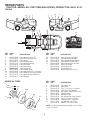
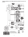
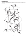
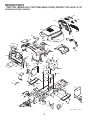
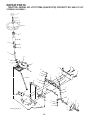
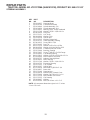
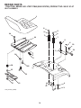
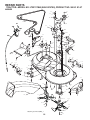
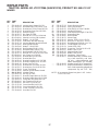
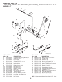
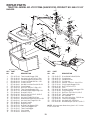
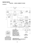
SERVICE
I0700022
IPL, LT2217 CMA, 2007-01, 504 11 15-02
96061019700
LT2217CMA
Spare parts
Ersatzteile
Pièces détachées
Reserve onderdelen
Repuestos
Reservdelar
504 11 15-02
ILLUSTRATED PARTS LIST
MFG. ID NO. 96061019700
CUSTOMER CATALOG NO. LT2217CMA
PRODUCT NO. 960 61 01-97
532 40 84-43 Rev. 6 06.12.07 AP
REPAIR PARTS
TRACTOR- -MODEL NO. LT2217CMA (96061019700), PRODUCT NO. 960 61 01-97
DECALS
14
3
7
7
21 16
17
6
3
14
4
5
9
20
11
2
8
_ 90N
MAX +
12
1
10
16
KEY
NO.
PART
NO.
DESCRIPTION
1
2
3
4
5
6
7
8
9
10
11
12
13
532 40 03-89
532 19 68-41
532 18 95-53
532 40 86-73
532 18 57-73
532 18 04-32
532 40 85-35
532 40 91-51
532 18 39-30
532 14 50-05
532 18 21-66
532 15 97-37
532 18 39-31
Decal Warning Sym. CE
Decal Warning Eng. Sym.
Decal Hood
Decal Replacement
Decal Wheel Steering
Decal 100 DBA
Decal Side Panel
Decal Engine HP
Decal Fender Logo
Decal Bat Dan/Poi P/L Sym Wpn
Decal Mower Cut Finger Symbol
Decal Brake/Clutch Symbol Lt
Decal Bagger
WHEELS & TIRES
1
2
5,8
4,10
7
3,9
6
11
_ 150N
MAX +
13
KEY
NO.
14
16
17
20
21
-----
PART
NO.
532 15 97-36
532 19 68-42
532 14 08-37
532 16 69-60
532 16 62-86
532 13 83-11
532 18 10-90
532 18 10-91
532 40 84-34
DESCRIPTION
Decal Chassis Hot Muffler
Decal Warning Cutfinger
Decal Saddle Brake Parking
Decal Bypass Fender CRD
Decal Hex Belt Sch 92 CRD
Decal Lift Handle
Pad Footrest RH
Pad Footrest LH
Manual Operator's (Euro)
KEY
NO.
PART
NO.
DESCRIPTION
1
2
3
4
5
6
7
8
9
10
11
--
532 05 91-92
532 06 51-39
532 10 62-22
532 05 99-04
532 13 83-36
532 12 49-57
532 12 49-59
532 13 83-37
532 12 20-82
532 12 49-26
532 17 50-39
532 14 43-34
Cap Valve Tire
Stem Valve
Tire F Ts 15 x 6 0 - 6 Service
Tube Inner Front #35060
Rim Asm 6" front Silver Service
Fitting Grease
Bearing Flange
Rim Asm 8"rear Silver Service
Tire R Ts 20 x 10-8 Service
Tube Rear 9 5 x 8 Service
Cap Axle Blk 1 50 x 1 00
Sealant, Tire (10 oz. tube)
NOTE: All component dimensions given in U.S. inches
1 inch = 25.4 mm
wheel_1
2
TRACTOR- -MODEL NO. LT2217CMA (96061019700), PRODUCT NO. 960 61 01-97
SCHEMATIC
12VDC
AMMETER
(OPTIONAL)
RED
STARTER
SOLENOID
BATTERY
STARTER
RED
RED
A
M
FUSE
15 AMP
WHITE
BLACK
S
B
M
A1
G
K
AC
BL
L
BLACK
A2
FBI BUZZER
CLUTCH / BRAKE
(PEDAL UP)
FBI
SWITCH
ATT'MENT CLUTCH
(CLUTCH OFF)
GREEN
ORANGE
OPERATOR PRESENCE
85 RELAY 86
1
30
87
RED
87A
BLACK
GRAY
OPERATOR PRESENCE
85 RELAY 86
2
30
87
87A
SEAT SWITCH
(NOT OCCUPIED)
BAGGER
INTERLOCK
(NO BAG,
CHUTE OR
PLUG)
BLACK
BLACK
BLACK
GROUNDING
CONNECTOR
FUEL
LINE
SPARK
PLUGS GAP
(2 PLUGS ON
TWIN CYL. ENGINES)
IGNITION
UNIT
BLUE
RED
28 VOLTS AC @ 3600 RPM (REGULATOR DISCONNECTED)
CARBURETOR SOLENOID
(iF SO EQUIPPED)
RED
REGULATOR
ALTERNATOR
CHARGING SYSTEM OUTPUT
15 AMP DC @ 3600 RPM
BROWN
BLACK
LIGHT SWITCH
HEADLIGHTS
REVERSE SWITCH
IGNITION SWITCH
POSITION
CIRCUIT
OFF
RUN/OVERRIDE
M+G+A1
B+A1
RUN
START
B+A1
B + S + A1
“MAKE”
WIRING INSULATED CLIPS
NOTE: IF WIRING INSULATED CLIPS
WERE REMOVED FOR SERVICING OF
UNIT, THEY SHOULD BE REPLACED
TO PROPERLY SECURE YOUR WIRING.
L+A2
03050
3
REMOVABLE
CONNECTIONS
87
86 87A 85
30
NON-REMOVABLE
CONNECTIONS
RELAY
REPAIR PARTS
TRACTOR- -MODEL NO. LT2217CMA (96061019700), PRODUCT NO. 960 61 01-97
ELECTRICAL
22
21
24
41
43
40
27
26
27
27
42
81
25
16
16
34
33
30
92
94
48
66
29
93
27
28
66
197436
58
2
1
59
16
4
REPAIR PARTS
TRACTOR- -MODEL NO. LT2217CMA (96061019700), PRODUCT NO. 960 61 01-97
ELECTRICAL
KEY
NO.
PART
NO.
DESCRIPTION
1
2
16
21
22
24
25
26
27
28
29
30
33
34
40
41
42
43
48
58
59
66
81
92
93
94
532 14 49-27
874 76 04-12
532 17 61-38
532 18 37-59
532 00 41-52
532 12 47-80
532 16 59-87
532 17 51-58
873 51 04-00
532 12 77-25
532 19 27-49
532 19 33-50
532 14 04-01
532 11 07-12
532 19 74-36
871 11 04-08
532 13 15-63
532 19 25-07
532 14 08-44
532 16 94-19
532 18 03-79
817 49 06-08
532 10 97-48
532 19 66-15
532 19 25-40
532 19 18-34
Battery
Bolt Hex Hd 1/4-20 unc x 3/4
Switch Interlock
Harness Asm Light W/4152J
Bulb Light #1156
Cable Starter
Cable Battery Crd 56" Red
Fuse
Nut Keps Hex 1/4-20 unc
Cable Ground 6 Ga. 18" Black
Switch Seat
Switch Ignition
Key Ignition
Switch Light
Harness Ignition
Bolt Flk Fin Hex 1/4-20 unc x 1/2
Cover Terminal Red
Solenoid
Adapter Ammeter Rectangular
Buzzer Crd
Switch FBI CRD
Screw Thdrol 3/8-16 x 1/2 Ty-Tt
Relay Asm
Harness Pigtail
Screw Plastite 10-14 x 2.0
Module Reverse
NOTE: All component dimensions given in U.S. inches
1 inch = 25.4 mm
5
REPAIR PARTS
TRACTOR- -MODEL NO. LT2217CMA (96061019700), PRODUCT NO. 960 61 01-97
CHASSIS AND ENCLOSURES
259
264
258
28
263
17
261
256
39
165
18
24
189 188 188
187
187
186
89
26
30
189
190
25
278
24
209
266
171
58
171
5
26 25
209
69
198
31
172
184
170
173
5
209
11
9
15
208
265
209
209
3
175
209
8
26
6
179
209
8
16
185
1
35
24
10
33
209
13
145
3
37
26
162
26
37
209
164
35
3
205
209
205
163
207
34
209
24
208
26
38
2
38
Chassis_Elite Pro_CRD_2
6
REPAIR PARTS
TRACTOR- -MODEL NO. LT2217CMA (96061019700), PRODUCT NO. 960 61 01-97
CHASSIS AND ENCLOSURES
KEY
NO.
PART
NO.
1
2
3
5
6
8
9
10
11
13
15
532 17 46-20
532 18 03-84
817 06 06-12
532 15 52-72
532 18 44-19
532 12 64-71
532 19 46-88
872 14 06-08
532 17 49-96
532 17 52-55
874 18 05-12
16
17
18
24
25
26
28
873 51 05-00
532 19 47-57
532 18 49-21
874 78 06-16
819 13 13-12
873 80 06-00
532 19 29-15
30
31
33
34
35
37
38
39
58
69
89
145
162
532 19 73-44
532 16 51-56
532 18 11-93
532 18 11-94
872 11 06-06
817 49 05-08
532 18 17-48
532 40 78-07
532 18 43-22
532 14 24-32
532 19 73-66
532 15 65-24
532 18 03-82
KEY
NO.
DESCRIPTION
Chassis
Drawbar
Screw 3/8-16 x 3/4
Bumper Hood/Dash
Saddle
Clip Insulator 13/32 Mtg. Hole
Dash
Bolt, Carriage 3/8-16 x 3/4
Panel, Dash, L.H.
Panel, Asm. Dash R.H.
Screw, Machine, Truss Head
5/16-18 unc x 3/4
Nut
Hood
Bumper Hood
Bolt
Washer 13/32 x 13/16 x 12 Ga.
Nut
Grille /Lens Asm (Key #'s 258,
259, 261, 263, 264)
Fender
Bracket, Fender Support
Footrest, L.H.
Footrest, R.H.
Bolt
Screw Thdrol 5/16-18 x 1/2 TYT
Bracket Asm Pivot Mower Rear
Bracket Pivot
Duct Air
Screw Hex 1/4-1/2 unc
Console
Rod Pivot Chassis/Hood
Bracket Exten Chassis Lh CRD
PART
NO.
163
164
165
170
171
532 18 03-83
532 16 56-05
532 18 13-56
532 19 94-88
872 14 06-20
172
173
175
179
184
185
186
187
188
189
190
198
205
207
208
209
256
258
259
261
263
264
265
266
278
819 13 20-16
873 51 06-00
532 18 82-03
532 18 82-02
532 17 46-62
532 18 11-01
532 16 07-93
532 12 50-04
819 06 12-16
810 07 10-00
871 08 10-10
532 16 89-37
817 49 06-08
817 67 05-08
817 67 06-08
817 00 06-12
532 18 13-61
532 18 97-55
532 18 97-54
532 18 97-53
532 18 38-33
532 18 38-32
532 18 57-04
532 18 57-03
532 19 16-11
DESCRIPTION
Bracket Exten Chassis Rh CRD
Support Battery CRD
Cover Battery
Backplate Asm CRD
Bolt Rdhd Sqnk
3/8-16 x 2-1/2 Gr. 5
Washer 13/32 x 1-1/4 x 16 Ga.
Nut, Keps Hex 3/8-16 unc
Guard Trap
Rod Pivot FBI CRD
Bracket Actuator Bagger CRD
Knob Rod Brake Parking
Latch Asm Mulch/Bagger
Nut Weld
Washer #10
Washer Lock #10
Screw Pan Hd Phillip 10-24 x 5/8
Nut, Push
Screw Thdrol 3/8-16 x 1/2
Screw 5/16-18 x 1/2
Screw Thdrol 3/8-16 x 1/2
Screw Hex Wsh Thdrol 3/8-16
Cover Fender
Lens Grille RH
Lens Grille LH
Insert Grille
Bezel Grille RH
Bezel Grille LH
Seal RH Side Bagger
Seal LH Side Bagger
Screw 10 x 3/4 Single Lead Hex
NOTE: All component dimensions given in U.S. inches. 1
inch = 25.4 mm.
7
REPAIR PARTS
TRACTOR- -MODEL NO. LT2217CMA (96061019700), PRODUCT NO. 960 61 01-97
DRIVE
295
47
183
38
268
183
263
183
275
51
52 172
57
185
183
81 16
199
16
293
264
199
199
51
84
95
199
171
197
16
265
266
261
292
262
96
266
295
253
254
161 159
207
169
9
181
263
162
65
112
14
171 163
163
171
56
158
207
186
14
294
66
120
167
83
177
182
203
168
166 42
21
43
183
187
259
40
8
10
38
42
82 165 156
50
183 50
150
187
39
48
151
27
255
62
35
214
51
49
35 36
34
36
47
37
258
36
35
120
22
255
263
28
30
27
36
35
258
16
76
78
75
53
30
29
77
252
263
74
252
96
27
25
24 19
55
263
16
73
77
200
1
15
drive-hydro_CRD_Laser_22
71
8
252
215
263
REPAIR PARTS
TRACTOR- -MODEL NO. LT2217CMA (96061019700), PRODUCT NO. 960 61 01-97
DRIVE
KEY
NO.
PART
NO.
1
-------
8
9
10
14
15
16
19
21
22
24
25
27
28
29
30
34
35
36
37
38
39
40
42
43
47
48
49
50
51
52
53
55
56
57
62
65
66
71
73
74
75
76
77
78
81
82
83
84
95
96
532 19 27-06
532 19 81-44
876 02 04-16
810 04 04-00
874 49 05-44
873 80 05-00
873 80 06-00
532 13 05-64
532 17 56-07
873 35 06-00
532 19 20-36
876 02 04-12
532 17 57-65
532 07 16-73
532 16 95-92
532 17 55-78
532 12 01-83
819 21 16-16
532 12 49-63
532 16 59-36
874 76 06-44
532 12 49-65
819 13 13-12
819 11 10-12
532 12 77-83
532 15 44-07
532 12 32-05
872 11 06-12
873 68 06-00
873 68 05-00
532 19 96-52
532 10 57-09
817 06 06-20
532 17 01-40
532 12 48-72
810 04 07-00
532 15 47-78
532 16 91-83
532 16 91-82
532 13 70-57
532 12 17-49
812 00 00-01
532 12 35-83
532 12 17-48
532 17 00-06
532 16 57-11
819 17 12-16
532 17 00-07
532 17 00-15
532 12 47-88
DESCRIPTION
Transaxle Hydro Gear 321-0510
(Order parts from transaxle manufacturer)
Rod, Shift Fender Adjust Lt
Clutch Asm Noram
Pin, Cotter 1/8 x 1
Washer, Lock Hvy Helical
Bolt Hex FGHD 5/16-18 x Gr 5
Nut Lock Hex W/Ins 5/16-18 unc
Nut Lock Hex w/Ins 3/8-16 unc
Knob
Rod, Brake
Nut
Spring, Rod, Brake
Pin, Cotter 1/8 x 3/4
Rod, Parking Brake
Cap, Parking Brake
Bracket, Mfg. Transaxle
Shaft, Asm Pedal Foot CRD
Bearing, Nylon
Washer 21/32 x 1 x 16 Ga.
Pin, Roll 3/16 x 1"
Pulley Flat Composite 3.06"
Bolt Fin Hex 3/8-16 unc x 2-3/4
Spacer, Split 395 x 59 Bzp
Washer 13/32 x 13/16 x 12 Ga.
Washer 11/32 x 5/8 x 12 Ga.
Pulley, Idler, V Groove Plasitc
Bellcrank Clutch Grnd Drv
Retainer, Belt Style Spring
Bolt Carr. Sh. 3/8-16 x 1-1/2 Gr. 5
Nut, Crownlock 3/8-16 unc
Nut Crownlock 5/16-18
Link, Clutch 7.66
Spring, Return, Clutch
Screw 3/8-16 x 1-1/4
V-Belt Kev 112" 0650 CRD
Cover, Pedal
Washer
Keeper, Belt Engine F-Proof
Strap, Torque, Lh
Strap, Torque, Rh
Spacer, Split
Washer 25/32 x 1-1/4 x 16 Ga.
Ring, E
Key, Square
Washer 25/32 x 1-5/8 x 16 Ga.
Asm, Shaft,Cross Rear
Spring, Torsion
Washer 17/32 x 3/4 x 16 Ga.
Link, Transaxle
Control Asm Bypass Hydro
Spring, Retainer 1”
KEY
NO.
PART
NO.
DESCRIPTION
112
120
150
151
156
158
159
161
162
163
165
166
167
168
169
171
172
177
181
182
183
185
186
187
197
199
200
203
207
214
215
252
253
254
255
258
259
261
262
263
264
265
266
268
275
292
293
294
295
819 09 12-10
873 90 06-00
532 16 58-50
819 13 32-10
532 16 60-02
532 16 55-89
532 18 39-00
872 14 04-06
873 68 04-00
874 78 04-16
532 16 56-23
817 49 05-10
532 16 55-88
532 16 54-92
532 16 55-80
817 49 06-08
532 17 02-71
532 16 59-32
532 18 02-11
532 18 26-82
532 19 95-32
532 17 00-08
532 16 56-14
817 58 05-20
532 16 96-13
532 16 96-12
872 14 05-08
871 17 07-80
532 16 98-45
532 17 56-09
532 17 56-52
819 13 16-16
532 17 50-28
817 00 06-16
532 17 56-08
532 17 80-62
532 18 02-12
532 13 14-94
872 11 06-22
817 00 06-12
532 19 76-08
532 18 20-13
532 18 20-61
532 18 24-02
819 13 16-14
532 40 02-71
872 14 06-28
532 19 70-33
532 17 91-14
Washer 9/32 x 3/4 x 10 Ga.
Nut Lock Flg. 3/8-16 unc
Bushing, Bellcrank Grnd Dr
Washer 13/32 x 2 x 10 Ga.
Washer Srrted 5/16 ID x 1.125
Bracket Shift Mount
Hub Shift
Bolt Rdhd Sqnk 1/4-20 x 3/4 Gr 5
Nut Crownlock 1/4-20 unc
Bolt Hex Fin 1/4-20 unc x 1 Gr 5
Bracket Pivot Lever
Screw 5/16-18 x 5/8
Bracket Support Shift CRD
Bolt Shoulder 5/16-18 x .561
Plate Fastening Lt
Screw Thdrol 3/8-16 x 1/2 Ty-Tt
Shaft Asm Shifter Frt CRD
Keeper Flat Idler 3.06" CRD
Bracket Idler Ground Drive CRD
Keeper Belt 2.5" Od V-Idler CRD
Pulley V-Idler 2.50" Od CRD
Link Shift
Hub Tapered Round CRD
Screw Thdrol 5/16-18 x 1.25
Nyliner Snap-In 5/8
Bolt Shoulder 5/16-18 unc
Bolt RDHD SQNK 5/16-18 x 1
Bolt Hex 7/16-20 x 5
Washer Nylon Rear
Shaft Asm. Brake
Rod Brake Hydro
Washer 13/32 x 1 x 16 Ga.
Bracket Cable Chassis
Screw 3/8-16 x 1
Brace Shaft Brake Mtg.
Clip Retainer
Bracket Pulley
Pulley Idler
Bolt Carr. 3/8-16 x 2-3/4 Gr.5
Screw 3/8-16 x 3/4
Bracket Idler
Spacer Idler Chassis
Shield Idler Mower
Guard Muffler
Washer 13/32 x 1 x 14 Ga.
Spacer
Bolt Carr. 3/8-16 x 3 1/2
Nut Jam 3/8-16
Pulley Idler
NOTE: All component dimensions given in U.S. inches
1 inch = 25.4 mm
9
REPAIR PARTS
TRACTOR- -MODEL NO. LT2217CMA (96061019700), PRODUCT NO. 960 61 01-97
STEERING ASSEMBLY
38
97
34
39
1
41
42
37
37
36
44
88
91
43
71
67
68
46
29
67
8
6
13
2
17
82
65
46
6
87
5
8
87
40
68
32
5
29
4
3
43
11
15
29
33
34
35
10
43
95
8
steering_pl.lt_60_r1
10
REPAIR PARTS
TRACTOR- -MODEL NO. LT2217CMA (96061019700), PRODUCT NO. 960 61 01-97
STEERING ASSEMBLY
KEY
NO.
1
2
3
4
5
6
8
10
11
13
15
17
29
32
33
34
35
36
37
38
39
40
41
42
43
44
46
65
67
68
71
82
87
88
91
95
97
PART
NO.
532 19 46-37
532 18 47-06
532 16 98-40
532 16 98-39
532 12 49-31
532 12 17-48
812 00 00-29
532 17 51-21
810 04 06-00
532 13 65-18
532 14 52-12
532 19 07-53
817 00 06-12
532 17 01-62
819 11 12-16
810 04 05-00
873 54 05-00
532 15 50-99
532 15 29-27
532 19 46-03
819 11 38-12
873 54 06-00
532 18 67-37
532 16 96-33
532 12 17-49
532 19 07-52
532 12 12-32
532 16 03-67
872 11 06-18
532 16 98-27
532 17 51-46
532 19 99-78
532 17 39-66
532 17 51-18
532 17 55-53
532 18 89-67
874 78 05-64
DESCRIPTION
Steering Wheel
Front Axle Assembly
Spindle Assembly, L.H.
Spindle Assembly, R.H.
Bearing, Race, Thrust, Hardened
Washer 25/32 x 1-5/8 x 16 Ga.
Ring, Klip
Link, Drag
Washer, Lock
Spacer Axle
Nut Hex Flange Lock
Shaft Assembly, Steering
Screw 3/8-16 x 3/4
Rod, Tie
Washer 11/32 x 3/4 x 16 Ga.
Washer Lock Hvy Hlcl Spr 5/16
Crownlock Nut 5/16-24 unf
Bushing, Steering
Screw TT #I0-32 x 5 x 3/8 Flange
Cap Wheel Steering
Washer 11/32 ID x 2 3/8 OD x 12 Ga.
Nut Crownlock 3/8-24 unf
Adaptor, Steering Wheel
Boot, Steering
Washer 25/32 x 1-1/4 x 16 Ga.
Extension Steering
Cap, Spindle
Spacer Axle
Bolt Rdhd Sq 3/8-16 x 2-1/4
Brace Axle
Steering Asm.
Bracket Susp. Chassis Front
Washer Flat .781 x 1-1/2 x .14
Bolt Shoulder 7/16-20 unc
Clip Steering
Washer
Bolt 5/16-18 unc x 4" L Gr. 5
NOTE: All component dimensions given in U.S. inches
1 inch = 25.4 mm
11
TRACTOR- -MODEL NO. LT2217CMA (96061019700), PRODUCT NO. 960 61 01-97
ENGINE
3
2
72
1
81
13
25
4
78
38
32
14
44
78
46
45
23
31
37
8
33
122
119
120
121
122
29
Gua
rd_
a
8
sse
mb
ly_
19
126
123
OPTIONAL EQUIPMENT
124
Spark Arrester
125
engine-bs.1cyl_52
122
12
TRACTOR- -MODEL NO. LT2217CMA (96061019700), PRODUCT NO. 960 61 01-97
ENGINE
KEY
NO.
PART
NO.
1
2
3
532 17 05-51
817 72 04-08
--------
4
8
13
14
23
25
29
31
32
33
37
38
44
45
46
72
78
81
119
120
121
122
123
124
125
126
532 13 73-52
532 17 18-77
532 16 52-91
532 14 84-56
532 16 98-37
532 19 06-95
532 13 71-80
532 40 75-52
532 19 77-25
532 12 34-87
532 13 70-40
532 18 16-54
817 67 04-12
817 00 06-12
819 09 14-16
532 19 23-34
817 06 06-20
873 51 04-00
532 19 97-68
532 19 97-67
532 19 66-88
532 13 77-29
817 67 05-08
532 41 05-24
532 41 05-25
817 00 05-12
DESCRIPTION
Control Throttle/Choke
Screw Hex Thd Cut 1/4-20 x 1/2
Engine Briggs Model 31E777
(Order parts from engine manufacturer)
Muffler
Bolt 5/16-18 UNC x 3/4 w/Sems
Gasket Muffler
Tube Drain Oil Easy
Shield Brn/Dbr Guard
Control Choke
Kit Spark Arrestor (Flat Scrn)
Tank Fuel 2.00
Cap Asm Fuel
Clamp Hose Blk
Line Fuel
Plug Drain Oil Easy
Screw Hexwsh thdrol 1/4-20 x 3/4
Screw Hexwsh Thdr 3/8-16 x 3/4
Washer 9/32 x 7/8 x 16 Ga.
Screw Socket Head 5/16-18 x .75
Screw 3/8-16 x 1-1/4
Nut Keps Hex 1/4-20 UNC
Guard Engine LH
Guard Engine RH
Clip Threaded
Screw 1/4-20 x 5/8
Screw 5/16-18 x 1/2
Shield LH
Shield RH
Screw 5/16-18 x 3/4
NOTE: All component dimensions given in U.S. inches
1 inch = 25.4 mm
Engine Power Rating Information
The gross power rating for individual gas engine models is labeled in accordance with SAE (Society of Automotive
Engineers) code J11940 (Small Engine Power & Torque Rating Procedure), and rating performance has been obtained and corrected in accordance with SAE J1995 (Revision 2002-5). Actual gross engine power will be lower and is affected by, among other things, ambient operating conditions and engine-to-engine variability. Given both
the wide array of products on which engines are placed and the variety of environmental issues applicable to operating the equipment, the gas engine will not develop the rated gross power when used in a given piece of power
equipment (actual “on-site” or net horsepower). This difference is due to a variety of factors including, but not limited to, accessories (air cleaner, exhaust, charging, cooling, carburetor, fuel pump, etc.), application limitations, ambient operating conditions (temperature, humidity, altitude), and engine-to-engine variability. Due to manufacturing and capacity limitations, Briggs & Stratton may substitute an engine of higher rated power for this Series engine.
13
REPAIR PARTS
TRACTOR- -MODEL NO. LT2217CMA (96061019700), PRODUCT NO. 960 61 01-97
SEAT ASSEMBLY
1
8
8
9
14
9
7
7
10
5
6
22
21
2
24
5
16
25
15
11
13
17
12
4
3
seat_lt.knob_7(CRD)
14
REPAIR PARTS
TRACTOR- -MODEL NO. LT2217CMA (96061019700), PRODUCT NO. 960 61 01-97
SEAT ASSEMBLY
KEY
NO.
PART
NO.
DESCRIPTION
1
2
3
4
5
6
7
8
9
10
11
12
13
14
15
16
17
21
22
24
25
532 19 78-95
532 14 05-51
871 11 06-16
819 13 16-10
532 14 50-06
873 80 06-00
532 12 41-81
817 00 06-16
819 13 16-14
532 19 55-30
532 16 63-69
532 17 46 48
532 12 12-48
872 05 04-12
532 13 43-00
532 12 12-50
532 12 39-76
532 17 18-52
873 80 05-00
819 17 19-12
532 12 70-18
Seat
Bracket Pnt Pivot Fender
Bolt Fin Hex 3/8-16 x 1
Washer Flat 13/32 x 1 x 10 Ga.
Clip Push In Hinged
Nut Lock Hex W/Ins 3/8-16
Spring Seat Cprsn 2 250 Blk Zi
Screw 3/8-16 x 1.5
Washer 13/32 x 1 x 14 Ga
Pan Pnt Seat
Knob Seat Adj. Wingnut
Bracket Pnt Mounting Switch
Bushing Snap Blk Nyl 50 Id
Bolt Rdhd Sht Nk 1/4-20 x 1-1/2
Spacer Split
Spring Cprsn
Nut Lock 1/4 Lge Flg Gr. 5 Zinc
Bolt Shoulder 5/16-18 unc-2A
Nut Hex Lock w/Ins 5/16-18
Washer 17/32 x 1-3/16 x 12 Ga.
Bolt shoulder 5/16-18 x .62
NOTE: All component dimensions given in U.S. inches
1 inch = 25.4 mm
15
REPAIR PARTS
TRACTOR- -MODEL NO. LT2217CMA (96061019700), PRODUCT NO. 960 61 01-97
MOWER
40
41
56
32
36
84
55
68
36
67
30
158
185
41
21
36
17
36
24
26
44
od
_7
152
30
32
36
124
61
27
lu
tc
h
_m
46
_c
33
42
2
30
30
32
21
28
31
3
21
30
40
23
21
25
124
21
33
5
6
18
32
4
21 41
31
19
35
1
2
41
41
21
34
119 116
21
116 117
119
117
36
22
2
21
46
124
130
13
18
15
2
46
2
14
131
11
45
69
163
161
162
9
16
8
162
36(92cm)_deck-elect.(CRD)_1
16
9
20
REPAIR PARTS
TRACTOR- -MODEL NO. LT2217CMA (96061019700), PRODUCT NO. 960 61 01-97
MOWER
KEY
NO.
PART
NO.
DESCRIPTION
1
2
3
4
5
6
8
9
11
13
14
15
16
17
18
19
20
21
22
23
24
25
26
27
28
30
31
32
33
34
35
36
40
41
44
45
46
55
532 40 01-08
872 14 05-06
532 16 55-69
532 16 55-58
532 12 46-70
532 16 55-57
532 18 17-12
810 03 06-00
532 18 63-85
532 13 76-45
532 12 87-74
532 11 04-85
532 18 63-86
872 14 06-10
872 11 06-06
532 13 28-27
532 18 17-13
873 68 05-00
532 19 95-90
532 16 54-46
532 16 52-42
532 16 52-44
532 40 01-10
532 16 55-68
532 16 55-67
532 17 39-84
532 18 76-90
532 17 57-07
532 40 02-34
532 40 01-07
532 40 01-06
532 14 67-63
873 68 06-00
873 90 06-00
532 17 55-38
532 17 55-39
532 13 77-29
532 19 94-98
Housing Asm. Mower 92 CRD
Bolt Rdhd Sqnk 5/16-18 unc x 3/4
Bracket Asm. S-Bar Chass 92 CRD
Bracket Bar Sway Deck 92 CRD
Retainer Spring
Bar Sway 92 CRD
Bolt 3/8-24 x 1.25 Gr. 8 Patched
Washer Lock Hvy 3/8 Unplated
Blade 3-1 Lh 92 CRD
Shaft Asm. W/Lower Bearing
Housing Mandrel Vented (Machd)
Bearing Ball Mandrel
Blade 3-1 Rh 92 CRD
Bolt Carriage 3/8-16 x 1-1/4
Bolt Rdhd Sqnk 3/8-16 x 3/4
Bolt Shoulder 5/16-18 Thd Form
Bolt 3/8-24 x 1.25 Gr. 8 Ptch Lhthd
Nut Crown Lock 5/16-18
Bracket Idler Sprt 92 CRD
Bracket Idler Sprt
Bracket Suspension LF 92 CRD
Bracket Suspension RF 92 CRD
Brace Susp Frt CRD
Bracket Asm. Susp RR 92 CRD
Bracket Asm. Susp LR 92 CRD
Screw Thd Rolling
Washer Spacer Mower Vented
Mandrel Pulleys
Nut Flg Top Lock
Bracket Gauge Wheel Lf 92 CRD
Bracket Gauge Wheel Rf 92 CRD
Pulley Idler V-Groove Dim 4.25
Nut Crownlock 3/8-16 unc
Nut Lock Flg. 3/8-16 unc
Cover Mandrel Lh 92 CRD
Cover Mandrel Rh 92 CRD
Screw Thd Roll 1/4-20 x 5/8
Arm Idler 92 CRD
KEY
NO.
PART
NO.
56
61
67
68
69
84
116
117
119
124
130
131
152
158
161
162
163
185
---
532 16 57-23
532 19 94-86
532 10 69-32
532 40 20-08
532 16 54-82
532 15 60-85
532 19 34-06
532 17 48-73
819 13 20-12
872 11 06-12
872 11 05-06
532 16 56-61
532 17 60-74
817 72 04-08
532 18 63-87
532 18 08-78
532 18 63-88
532 18 82-34
532 18 18-57
-----
532 18 18-58
532 40 13-73
DESCRIPTION
Spacer Retainer Mower
Spring Tension Belt
Knob Rd 3/8-16 Plstc Thds Blk
Hex-Belt 92 Mower
Shaft Asm W/Lwr Brg Rh Thd CRD
Keeper Belt Idler
Bolt Shoulder
Wheel Gage
Washer 13/32 x 1-1/4 x 12 Ga
Bolt Carr Sh 3/8-16 x 1-1/2 Gr. 5
Bolt Rdhdsqnk 5/16-18 unc x 3/4
Chute Bagger CRD 92cm
Cable Clutch CRD
Screw Hex Thd Cut 1/4-20 x 1/2
Blade Cross LH 92
Adapter Blade Cross
Blade Cross RH 92
Head Asm. Cable Clutch
Mandrel Assembly (Includes housing, shaft assembly, and bearing only - pulley/nut/washer and
blade bolt/washers not included)
Mandrel Asm CRD Lh Threads SVC
Replacement Mower, Complete (Std.
Deck - Order separately guage wheel
components key nos. 116 - 119)
NOTE: All component dimensions given in U.S. inches
1 inch = 25.4 mm
17
REPAIR PARTS
TRACTOR- -MODEL NO. LT2217CMA (96061019700), PRODUCT NO. 960 61 01-97
MOWER LIFT
29
28
27
25 24
23
7
41
8
49
37
5
38
30
3
40
36
1
50
13
26
4
6
6
11
5
2
4
12
13
19
13
20
15
31
32
13
KEY
NO.
1
2
3
4
5
6
7
8
11
12
13
15
16
17
18
19
20
23
PART
NO.
532 19 84-17
532 19 80-70
532 18 88-22
812 00 00-02
819 21 16-21
532 12 01-83
532 12 56-31
532 12 45-26
532 16 58-29
532 16 58-31
532 12 46-70
532 17 32-88
873 35 08-00
532 17 56-89
873 80 08-00
532 13 98-68
532 19 42-09
532 11 08-07
19
20
17 18 20
16
20
15
31
32
lift-rh.1piece_9
KEY
NO.
24
25
26
27
28
29
30
31
32
36
37
38
40
41
49
50
DESCRIPTION
Wire Asm Inner Spring W/Plunger
Shaft Asm. Lift
Pin Groove
E Ring #5133-62
Washer 21/32 x 1 x 21 Ga.
Bearing Nylon
Grip Handle Fluted
Button Plunger Black
Link Asm Lift L.H.
Link Asm Lift R.H.
Retainer Spring
Link Front
Nut Jam Hex 1/2-13 unc
Trunnion Blk Zinc
Nut Lock w/wsh 1/2-13 unc
Arm Suspension Mower
Pin Cotter 7/16 Bowtie Lock
Nut Special
18
PART
NO.
819 13 10-16
532 12 48-74
532 16 94-84
532 12 69-71
873 35 06-00
532 13 80-57
532 15 02-33
532 16 98-65
873 54 06-00
532 15 50-97
532 12 39-35
817 06 05-16
819 11 24-10
532 12 39-34
532 14 52-12
532 11 04-52
DESCRIPTION
Washer 13/32 x 5/8 x 16 Ga.
Spring 2-1/8"
Retainer Clip
Rod Adj Lift Zinc 7.49 Wrk Lg
Nut Hex Jam 3/8-16 Unc
Knob Inf 3/8-16 Unc Blk w/sym
Trunnion Infin Height
Bearing, Pvt. Lift.
Nut Crownlock 3/8-24
Pointer Height Indicator
Plug Hole Blk 1.485/1.515 Dia
Screw 5/16-18 x 1
Washer 11/32 x 1-1/2 x 10 Ga.
Scale Ind Height Blk
Nut hex Flange Lock
Nut Push Phos & Oil
NOTE: All component dimensions given in U.S. inches
1 inch = 25.4 mm
REPAIR PARTS
TRACTOR- -MODEL NO. LT2217CMA (96061019700), PRODUCT NO. 960 61 01-97
BAGGER
17
12
41
13
16
11
28
17
19
16
38
20
19
39
5
37
1
4
41
19
36
46
14
9
8
37
19
13
32
16
9
31
11
24
7
4
14
6
50
22
15
36
22
3
43
47
50
49
7
16
10
15
53
46
51
3
25
54
49
15
15
33
34
21
36_mul
ch plug
(CRD)
35
Bagger Asy (CRD)_14
KEY
NO.
PART
NO.
DESCRIPTION
1
3
4
5
6
7
8
9
10
11
12
14
15
16
17
19
20
21
22
24
25
28
31
532 16 52-49
532 12 39-76
532 16 99-16
874 98 10-24
874 98 10-32
873 40 10-00
532 18 13-54
872 14 04-18
532 18 12-82
532 16 57-19
532 18 88-48
874 52 06-36
532 12 46-70
873 90 06-00
872 14 05-06
873 90 05-00
532 18 88-47
532 19 38-38
532 16 57-81
532 16 57-83
532 19 37-05
532 16 57-87
532 16 94-84
Tube Handle Bagger CRD
Nut Lock 1/4 Lge Flg Gr. 5 Zinc
Handle Bagger w/Lvrs Blk CRD
Screw Pan Head #10-24 x 1.50
Screw Pan Hd
Nut Wiz Lock Hex Serr/Hd 10-24
Cover Bagger
Bolt Carr. 1/4-20 x 2.25d x Gr.5
Tube Support Bagger CRD
Bracket Support Upper Bag CRD
Bracket Pivot Lh
Bolt Fin Hex 3/8-16 x 2-1/4 Gr.5
Retainer Spring
Nut Lock Flange 3/8-16 unc
Bolt Rdhd Sht Sqnk 5/16 -18 unc x 3/4
Nut Lock Hex Flange 5/16-18
Bracket Pivot Rh
Bag Asm CRD
Bracket Side Bagger CRD
Tube Pivot Bagger CRD
Tube Front Bagger
Grip Handle
Retainer Clip
KEY
NO.
PART
NO.
DESCRIPTION
32
33
34
35
36
37
38
39
41
43
46
47
49
50
51
53
54
532 12 68-75
532 16 55-71
532 16 55-70
532 16 55-72
819 13 20-12
532 17 54-01
872 01 05-20
532 18 09-85
532 16 96-83
532 17 40-83
872 11 05-10
532 19 37-04
532 19 33-05
873 80 05-00
532 19 99-03
873 51 04-00
872 14 04-06
Rivet Rd Hd Drilled 3/8 Dia.
Plug Mulcher
Handle Mulcher
Pin Mulcher
Washer 13/32 x 1-1/4 x 12 Ga.
Plug Support Bagger CRD
Bolt 5/16-18 x 2-1/2
Seal
Bracket Pnt Adj Pvt Bagger CRD
Plug Tubing End
Bolt Carr. 5/16-18 x 1-1/4 Gr. 5
Tube Upper Bagger
Bar Spreader
Nut Lock Hex W/Ins. 5/16-18 unc
Latch Spring Bagger
Nut Keps Hex 1/4-20 Unc
Bolt Rdhd Sqnk 1/4-20 x 3/4 Gr. 5
NOTE: All component dimensions given in U.S. inches
1 inch = 25.4 mm
19