1
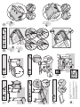
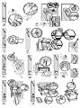
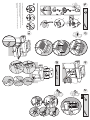
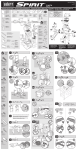
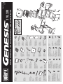
1 Inch Zinc Bolts (1/4 x 20 x 1 In.) - 4 Cinc 1 pulgada Pernos (1/4 x 20 x 1 pulg.) - 4 Ecrous en zinc de 1 pouce (1/4 x 20 x 1 po.) - 4 1/2 Inch Stainless Steel Hex Bolts (1/4 x 20 x 1/2 In.) - 12 Acero inoxidable 1/2 pulgada Pernos hexagonales (1/4 x 20 x 1/2 pulg.) - 12 Ecrous hexagonaux en acier inoxydable de 1/2 pouce (1/4 x 20 x 1/2 po.) - 12 11 mm (7/16 in.) Wrench - 1 Llave de 11 mm (7/16 pulg.) - 1 Clé de 11 mm (7/16 po.) - 1 Cookbox Assembly - 1 Ensamble de la caja de cocción - 1 Ensemble du boîtier de cuisson - 1 Bottom Tray - 1 Bandeja del fondo - 1 Plateau inférieur - 1 Frame Support - 2 Soporte del bastidor - 2 Support de coffrage - 2 Caster - 2 Rueda loca - 2 Ecrou - 2 Locking Caster - 2 Rueda loca con traba - 2 Ecrou de verrouillage - 2 Right Frame - 1 Bastidor derecho - 1 Coffrage droit - 1 Left Frame - 1 Bastidor izquierdo - 1 Coffrage gauche - 1 Plastic Plug - 2 Tapón plástico - 2 Bouchon en plastique - 2 Aluminium Washer - 6 Arandela de aluminio - 6 Rondelle en aluminium - 6 Nylon Washer - 14 Arandela de nilón -14 Rondelle en nylon - 14 1/2 Inch Black Zinc Hex Bolts (1/4 x 20 x 1/2 In.) - 8 Cinc negro 1/2 pulgada Pernos hexagonales (1/4 x 20 x 1/2 pulg.) - 8 Ecrous hexagonaux en zinc noir de 1/2 pouce (1/4 x 20 x 1/2 po.) - 8 Right Side Table - 1 Mesa lateral derecha - 1 Tablette latérale droite - 1 Knob - 3 Perilla - 3 Bouton - 3 Right Front Trim Assembly - 1 Moldura derecha delantera Ensamble - 1 Garniture avant droite Ensemble - 1 Right Trim Assembly - 1 Ensamble de la moldura derecha - 1 Ensemble de garniture droit - 1 Front Panel - 1 Panel delantero - 1 Panneau avant - 1 Catch-Pan Holder - 1 Sostenedor del plato recolector - 1 Support de l’égouttoir - 1 Rear Panel - 1 Panel trasero - 1 Panneau arrière - 1 Shoulder Bolt Screw (1/4 x 20 x 1 In.) - 4 Perno de tope (1/4 x 20 x 1 pulg.) - 4 Vis à boulon de la structure (1/4 x 20 x 1 po.) - 4 #8 - 32 Machine Screw - 4 Tornillo de máquina #8 - 32 - 4 Vis de mécanique de #8 - 32 - 4 Keps Nut - 2 Tuerca de enclavamiento - 2 Écrou Keps - 2 2 1/4 Inch Bolt (1/4 x 20 x 2 1/4 In.) - 2 Perno de 2 1/4 pulgadas (1/4 x 20 x 2 1/4 pulg.) - 2 Boulon de 2 1/4 pouces (1/4 x 20 x 2 1/4 po.) - 2 Catch-Pan - 1 Plato recolector - 1 Egouttoir - 1 Drip Tray - 1 Bandeja de goteo - 1 Plateau de recueil des gouttes - 1 Shroud - 1 Defensa - 1 Structure - 1 Left Trim Assembly - 1 Ensamble de la moldura izquierda - 1 Ensemble de garniture gauche - 1 Left Side Table - 1 Mesa lateral izquierda - 1 Tablette latérale gauche - 1 Side Burner - 1 Quemador lateral - 1 Brûleur latéral - 1 Bottom Tray Hardware - 6 Herramientas de ferreteria para la bandeja recolectora de grasa - 6 Boulonnerie de Plateau inférieur - 6 Cotter Pin - 2 Clavija hendida - 2 Goupille fendue - 2 Clevis Pin - 2 Pasador de horquilla - 2 Axe - 2 Screw - 5 Tornillo - 5 Vis - 5 Garniture avant gauche Ensemble - 1 Left Front Trim Assembly - 1 Moldura izquierda delantera Ensamble - 1 Door Handle - 2 Asa de la puerta - 2 Poignée de porte - 2 Right Door Panel - 1 Panel de la puerta derecha - 1 Panneau de porte droit - 1 Left Door Panel - 1 Panel de la puerta izquierda - 1 Panneau de porte gauche - 1 Warming Rack - 1 Rejilla para calentar - 1 Grille de maintien au chaud - 1 Cooking Grate - 2 Parrilla de cocción - 2 Grille de cuisson - 2 Flavorizer® Bar - 5 Barra Flavorizer® - 5 Barre Flavorizer® - 5 Disposable Drip Pan - 2 Bandeja de goteo desechable - 2 Egouttoir jetable - 2 8 18 9 10 21 13 14 2 2 5 19 11 12 TOOLS NEEDED: HeaE mientr RRAMIENTAS REQUERIDAS: OUTILS NECESSAIRES: 20 7 3 17 1 4 6 ASSEMBLY INSTRUCTIONS • INSTRUCCIONES DE MONTAJE • INSTRUCTIONS DE MONTAGE 310, 320 9 10 16 13 14 15 US ENGLISH 55981 US 10/06/06 NG 6- 3A 3B 4- 2 • aluminium • aluminio • aluminium 2- • Retournez l’ensemble du coffrage de façon à ce que les écrous se trouvent sur le sol. • Voltee el ensamble del bastidor de manera que las ruedas locas estén sobre el piso. • Flip over frame assembly so the casters are on the ground. 2- 1 2- 6 5B 3 - 5A 320 3. 1. 10 6 - 4 - 32-- 2. 13 4 4- 3C 4 - 9 8 b. b. a. 4- 2- 2- a. 7 • aluminium • aluminio • aluminium 12 2. 11 4 2- 1. 15 14 2 - b) a) 16 3a. b. c. • Do not fully tighten bezel screws until knob is aligned with valve stem. • No apriete totalmente los tornillos de las molduras decorativas sin antes haber alineado la perilla al vástago de la válvula. • Ne serrez pas les vis du support à fond tant que le bouton n’est pas aligné avec la tige de la valve. 17 18 19 20 2 - 21 4 - 320 • Refer to Owner’s Manual for clip installation warning. • Refiérase al Manual del Propietario para la advertencia referente a la instalación de la presilla. • Veuillez consulter le Manuel du Propriétaire pour l’installation de la pince.