1
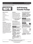
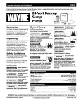
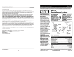
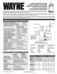
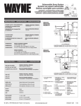
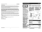
SEP4, SEP5,
SEP6 and SEP8
Operating Instructions & Parts Manual
Please read and save these instructions. Read carefully before attempting to assemble, install, operate or
maintain the product described. Protect yourself and others by observing all safety information. Failure to
comply with instructions could result in personal injury and/or property damage! Retain instructions for future
reference.
Sewer Ejector
Pump
Description
The submersible pump is designed
for home applications. The unit is
equipped with a 3-prong grounding
type power cord. Motor is oil-filled and
sealed for cooler running and designed
to operate under water. This pump is
not suitable for aquatic life, ponds or
fountains.
Unpacking
Inspect this unit before it is used.
Occasionally, products are damaged
during shipment. If the pump or
components are damaged, return
the unit to the place of purchase for
replacement. Failure to do so could
result in serious injury or death.
Important Safety
Instructions
READ AND FOLLOW ALL INSTRUCTIONS
Safety Guidelines
This manual contains information
that is very important to know and
understand. This information is
provided for SAFETY and to PREVENT
EQUIPMENT PROBLEMS. To help
recognize this information, observe the
following symbols:
Danger indicates an
imminently
hazardous situation which, if not avoided,
WILL result in death or serious injury.
Warning indicates a
potentially
hazardous situation which, if not avoided,
COULD result in death or serious injury.
Caution indicates a
potentially
hazardous situation which, if not avoided,
MAY result in minor or moderate injury.
Notice indicates
important
information, that if not followed, MAY
cause damage to equipment.
General Safety
Information
CALIFORNIA PROPOSITION 65
This product or
its power cord may
contain chemicals known to the State
of California to cause cancer and birth
defects or other reproductive harm.
Wash hands after handling.
GENERAL SAFETY INFORMATION
Do not
use to
pump flammable or explosive
fluids such as gasoline, fuel
oil, kerosene, etc. Do not
use in a flammable and/or explosive
atmosphere. Personal injury and/or
property damage could result.
This pump is
not designed
to handle salt water, brine, laundry
discharge or any other application
which may contain caustic chemicals
and/or foreign materials. Pump damage
could occur if used in these applications
and will void warranty.
All wiring must be
performed by a
qualified electrician.
If
the
basement has water or
moisture on the floor, do not
walk on wet area until all
power is turned off. If the shut-off box
is in the basement, call an electrician.
Remove pump and either repair or replace.
Failure to follow this warning could result
in fatal electrical shock.
Specifications
Power supply requirements
SEP4 . . . . . . . . . . . . . . . . . . . . . . . . 120V, 60 hz
SEP5, SEP6, and SEP8 . . . . . . . . . . 240V, 60 hz
Motor . . . . . . . . . . . . . . . . . . . . . . . . Single phase, oil filled
Horsepower/Current
SEP4 . . . . . . . . . . . . . . . . . . . . . . . . 1/2 HP, 12A @ 115VAC
SEP5 . . . . . . . . . . . . . . . . . . . . . . . . 3/4 HP, 7A @ 230VAC
SEP6 . . . . . . . . . . . . . . . . . . . . . . . . 1 HP, 8.5A @ 230VAC
SEP8 . . . . . . . . . . . . . . . . . . . . . . . . 2 HP, 12A @ 230VAC
Liquid temperature range . . . . . . . 40°F to 120°F
Circuit requirements . . . . . . . . . . . . 15 amps (min)
Dimensions. . . . . . . . . . . . . . . . . . . . . . 11 1/2 in. high x 9 3/4 in. base
Construction
Motor housing . . . . . . . . . . .
Volute . . . . . . . . . . . . . . . . . .
Impeller . . . . . . . . . . . . . . . . .
Shaft . . . . . . . . . . . . . . . . . . .
Seals . . . . . . . . . . . . . . . . . . . .
Discharge . . . . . . . . . . . . . . .
Cast Iron
Cast Iron
Cast Iron
Low carbon steel
Buna N
3 in. NPT
2 in. NPT (Adapter included)
REMINDER: Keep your dated proof of purchase for warranty purposes!
Attach it to this manual or file it for safekeeping.
© 2009 Wayne Water Systems
For parts, product & service information
visit www.waynepumps.com
332200-001 2/09
Operating Instructions and Parts Manual
General Information
Sewage Pump Systems:
Simplex System
A simplex system consists of one pump,
its control switch, and one basin. It is
used in applications where less than
six toilets (units) are discharged into
a basin. The simplex unit is generally
operated with a contactor to turn
the pump ON and OFF. The contactor
is activated by a single pole float
switch. The float switch is a wide-angle
differential switch that rises with the
liquid level and turns the pump ON.
As the liquid level decreases, the float
lowers and turns the pump OFF. The
switch differential is 120º.
Sewage Pump Systems:
Duplex System
A duplex system is used in applications
where more than six toilets (units) are
discharged into a basin. However, each
pump should be sized to handle the entire
flow in case one pump fails. The duplex
unit is controlled by a NEMA 1 control
panel that has an automatic alternator,
run lights, hand-off-auto switches, and
an alarm bell. The duplex control panel
is supplied with three float switches. The
floats are to be positioned so that the
lower float turns the pumps OFF. The
second float alternates turning first one
pump ON and then the other pump ON.
The third float will turn BOTH pumps ON
in case one pump cannot handle the flow.
The third float will also sound the alarm
(which remains on until the system is reset).
Functionally, the liquid in the basin rises
and trips the first float, but the pumps do
not turn ON. As the liquid level rises, it
trips the second float, activating one of the
pumps. Once the liquid level recedes and
no longer trips the second float, the pump
will turn OFF. If the second float is tripped
again, the other pump will turn ON.
If for some reason the liquid level
increases past the second float and trips
the third float, both pumps turn ON and
trips the alarm.
Under normal circumstances, the first
pump will handle the flow after the
second float is tripped. In those cases,
the liquid level will recede until it drops
the lower float. This action turns the
pump OFF. The next time that the liquid
level rises, the other pump turns ON. This
alternates the pumps; this prevents lockup and extends the lifer of both pumps.
Available Controls
For 115 volt only, a wide angle float
switch can be supplied with a plug-thru
series plug.
For 230 volt Simplex units, a NEMA 1
Simplex Controller with a hand-off-auto
switch and run light can be supplied.
This is supplied with a wide-angle
switch for automatic operation.
For 230 volt Duplex units, a NEMA 1
control panel can be supplied with
a hand-off-auto switches, run lights,
pump alternator, and an alarm bell.
This is supplied with a three float switch
system for automatic operation.
Installation
Always
disconnect
the power source before
attempting to install, service,
relocate or maintain the pump.
Never touch sump pump, pump motor,
water or discharge piping when pump is
connected to electrical power. Never handle
a pump or pump motor with wet hands or
when standing on wet or damp surface or
in water. Fatal electrical shock could occur.
Some models of this product include
a grounded plug for quick installation
anywhere a grounded outlet is
accessible. Some models must be
incorporated into the building’s
electrical system. Models without plugs
must be connected to a grounded
circuit. The circuit should be equipped
with a ground fault interrupter device.
All models without plug-in power cords
systems must be installed by a qualified
electrician. All models with a plug-in
power cords system should still have a
qualified electrician inspect the outlet
being used to ensure proper wiring.
Grounding
Blade
Grounded
Outlet
TEST
RESET
Power
Cord
Switch
Cord
Figure 3
The control switch is a wide-angle
system which prevents short cycling of
the pump motor and the consequential
problems that short cycling can cause.
The switch can be mounted on the
discharge pipe (just above the pump
discharge flange). See illustrations for
switch mounting arrangements.
Figure 1 - Simplex System
Figure 2 - Duplex System
www.waynepumps.com
2
Operating Instructions and Parts Manual
Installation
(Continued)
INSTALLATION BASICS:
1. NEVER lift this product by the
electrical cords.
2. Install pump in a sewage pit
that fulfills the minimum size
requirements (24 in. minimum).
Construct sump pit of tile, concrete,
steel or plastic. Do not install a pit
smaller than recommended.
3. The unit should be located and
rest on a solid, level foundation.
Do not place pump directly on clay,
earth, gravel or sandy surface. These
surfaces contain small stones, gravel,
sand, etc. that may clog or damage
the pump and cause pump failure.
Flood risk. If
flexible discharge
hose is used, make sure pump is secured
in sewage pit to prevent movement.
Failure to secure pump could allow pump
movement and switch interference and
prevent pump from starting or stopping.
4. Thread the discharge pipe or pipe
nipple into the discharge flange
connection.
5. A check valve MUST be used in a
solids-handling system. Mount the
check valve in a horizontal position
or at a 45º angle with the valve pivot
on top. In a vertical position, solids
tend to lodge on the valve flapper
and can prevent it from opening.
Main waste line to
sewer or septic tank
2 in. Discharge
pipe
6. Drill a 1/8 in. hole in the discharge
pipe 1 to 2 inches above the flange.
This will prevent air locking and loss
of prime at startup. A gate valve
should be installed in the system
after the check valve. This gate valve
should be a full port valve which
will pass 2 in. solids or as required by
state and local codes. The gate valve
permits removal of the pump and/
or the check valve for servicing (and
will minimize back-flow mess).
7. (OPTIONAL) Install a union between
the check valve and the pump so the
pump can be removed with the least
amount of disturbance of the piping.
8. Connect 2 in. rigid pipe to check
valve.
Support pump
and piping when
assembling and after installation.
Failure to do so could cause piping to
break, pump to fail, etc. which could
result in property damage and/or
personal injury.
9. Protect electrical cord from sharp
objects, hot surfaces, oil and
chemicals. Avoid kinking the cord and
replace damaged cords immediately.
IMPORTANT: Make sure there is
adequate room for tether switch to
swing freely during operation.
10. A pit cover must be installed to
prevent debris from clogging or
damaging the pump. All piping and
Upper level drainage
power cords will be brought through
the appropriate openings in the
basin cover. Do not modify existing
openings in any way.
All sewage basins
must be vented
to prevent a build-up of methane gas.
Consult your local codes for proper
venting. DO NOT install venting in
locations classified as hazardous in
accordance with the National Electrical
Code NFPA 70.
Operation
Always
disconnect
the power source before
attempting to install, service,
relocate or maintain the
pump. Never touch sewage pump, pump
motor, water or discharge piping when
pump is connected to electrical power.
Never handle a pump or pump motor
with wet hands or when standing on
wet or damp surface or in water. Fatal
electrical shock could occur.
1. Verify pump and switch operate
within the basin.
Risk of electrical
shock! This pump
is supplied with a grounding conductor
and grounding type attachment plug.
Use a grounded receptacle to reduce the
risk of fatal electrical shock.
Never cut off the round grounding
prong. Cutting the cord or plug will
void the warranty and make the pump
inoperable.
Vent pipe
Cleanout
2 in. gate valve
Dryer
2 in. Check
valve
Three prong
grounded
outlet
equipped
with a
ground fault
interruptor
Washer
Laundry tubs
Lavatory
Shower
45°
Elbow
Union
Pump
Float Switch
Flange
Floor drain
Washer drain
Figure 4 - Typical Installation
www.waynepumps.com
3
Operating Instructions and Parts Manual
Operation (Continued)
Maintenance
2. With the cover removed, add water
to the basin and observe the float
control switch operation.
Always disconnect
the electrical
supply before attempting to install,
service, relocate or perform any
maintenance. If the power source is out
of sight, lock and tag in the open (off)
position to prevent unexpected power
application. Failure to do so could result
in fatal electrical shock. Only qualified
electricians should repair this unit.
Improper repair could result in fatal
electrical shock.
3. Also, test alarm switch if installed.
4. Secure and seal basin cover.
Do not run your pump in a dry sump.
Do not attempt to
oil the motor. A
special oil has been put in the motor
housing at the factory. Use of any other
oil could damage the pump and WILL
void the warranty.
1. Let the pump cool for a minimum of
two hours before servicing because
the pump contains hot oil under
pressure and the motor is hot.
2. Disassembly of the motor prior to
expiration of warranty will void the
warranty. If repairs are required, see
troubleshooting chart.
3. Inlet should be kept clean and free
of all foreign objects and inspect
annually. A clogged inlet will
damage pump.
4. Pump should be checked monthly
for proper operation.
This pump contains
dielectric oil for
cooling. This oil can be harmful to
the environment. Check the state
environmental laws before disposing
this oil.
Pump #1
Discharge
Pump #2
Discharge
On Level
High Water Level
Alarm
Level
Low Water Level
Off Level
Figure 6 - Duplex System
Figure 5 - Simplex System
www.waynepumps.com
4
Operating Instructions and Parts Manual
Troubleshooting Chart
Symptom
Possible Cause(s)
Corrective Action
Pump will not start or run
1. Blown fuse, tripped breaker
2. Low line voltage
3. Defective motor
4. Defective float switch
5. Stuck/ jammed impeller
Pump starts and stops too
often
1. Back-flow of water from
piping
1. Install or replace check valve
2. Faulty float switch
2. Replace float switch
Pump will not shut off or
thermal protector turns off
1. Defective float switch
2. Obstacle in piping
3. Float obstructed
4. Low line voltage
5. Too many appliances on
circuit
1. Replace float switch
2. Remove pump and clean pump and piping
3. Make sure float move freely up and down
4. If voltage is under 108 volts, check wiring size
5. Install pump on dedicated circuit. IMPORTANT: Do not
use extension cord to power pump.
Pump operates but delivers
little or no water
1. Plugged impeller
2. Check valve installed
backwards
3. Pump air locked
1. Clean out impeller
2. Reverse position of check valve
6. Float obstructed
1. If blown, replace with proper sized fuse or reset breaker
2. If voltage is under 108 volts, check wiring size
3. Replace pump
4. Replace float switch
5. If impeller will not turn, remove housing and remove
blockage
6. Make sure float(s) move freely up and down
3. Check the 1/8 in. hole in discharge line between
pump and check valve; it should be 1 in. to 2 in. above
discharge flange and before the check valve
www.waynepumps.com
5
Operating Instructions and Parts Manual
For Replacement Parts or Technical Assistance,
Call 1-800-237-0987
Please provide following information:
- Model number
- Serial number (if any)
- Part description and number as shown in parts list
1
Address any correspondence to:
Wayne Water Systems
101 Production Drive
Harrison, OH 45030 U.S.A.
2
3
4
5
6
22
7
8
21
20
19
9
18
17
10
16
15
14
13 12
Ref.
No.
1
2
3
4
5
6
7
8
9
10
11
12
13
14
15
16
17
Description
Pipe plug 1/4 in. NPT
Lifting eye
Motor
Reducer bushing 3 in. NPT 2 in. NPT
1/2 - 13 UNC x 2 1/4 Hex head
Discharge flange 3 in.
3 in. Discharge gasket
Washer
1/2 - 13 UNC Hex nut
Volute
Volute wear ring
Impeller
Volute gasket
Shaft seal kit
Seal plate
Cover gasket
Capacitor
3/4 HP to 2 HP
1/2 HP only
Ref.
No.
18
19
20
21
22
Part Number Qty
16314
1
23124
1
SEE CHART
1
17436-001
16636
23100
23102
16635
16637
56603
23112
SEE CHART
16735
56884-002
56604
16855
1
2
1
1
4
2
1
1
1
1
1
1
1
23126
23126-002
1
1
23
24
11
Description
Motor housing
3/8 - 16 UNC x 1 1/4 Socket head
1/2 -13 UNC x 2 1/4 Hex head
Screw, 10 - 24 x 1/2
Power supply cord
1/2 HP
3/4 HP - 2 HP
Locking cable tie (not shown)
Dielectric oil - 1 gallon
(not shown)
Part Number Qty
41048-001
1
16798
3
16636
4
67050-001
2
31036-001
31036-002
17182-003
1
1
3
56435
1
MOTOR / IMPELLER CHART
www.waynepumps.com
6
HP
Motor Part Number
1/2
3/4
1
2
3710-004
3710-005
3710-006
3710-008
Impeller Part
Number
84341
84342
84343
84345
Operating Instructions and Parts Manual
Notes
www.waynepumps.com
7
Operating Instructions and Parts Manual
Limited Warranty
For one (1) year from the date of purchase, Wayne Water Systems will repair or replace, at its option, for the original purchaser
any part or parts of its Sump Pumps or Water Pumps (“Product”) found upon examination by Wayne Water Systems to be
defective in materials or workmanship. Please call Wayne Water Systems (1-800-237-0987) for instructions or see your dealer.
Be prepared to provide the model number and serial number when exercising this warranty. All transportation charges on
Products or parts submitted for repair or replacement must be paid by purchaser.
This Limited Warranty does not cover Products which have been damaged as a result of accident, abuse, misuse, neglect,
improper installation, improper maintenance, or failure to operate in accordance with Wayne Water System’s written
instructions.
THERE IS NO OTHER EXPRESS WARRANTY. IMPLIED WARRANTIES, INCLUDING THOSE OF MERCHANTABILITY AND FITNESS
FOR A PARTICULAR PURPOSE, ARE LIMITED TO TWO YEARS FROM THE DATE OF PURCHASE. THIS IS THE EXCLUSIVE
REMEDY AND ANY LIABILITY FOR ANY AND ALL INDIRECT OR CONSEQUENTIAL DAMAGES OR EXPENSES WHATSOEVER
IS EXCLUDED.
Some states do not allow limitations on how long an implied warranty lasts, or do not allow the exclusions or limitations of
incidental or consequential damages, so the above limitations might not apply to you. This limited warranty gives you specific
legal rights, and you may also have other legal rights which vary from state to state.
In no event, whether as a result of breach of contract warranty, tort (including negligence) or otherwise, shall Wayne Water
Systems or its suppliers be liable for any special, consequential, incidental or penal damages including, but not limited to
loss of profit or revenues, loss of use of the products or any associated equipment, damage to associated equipment, cost of
capital, cost of substitute products, facilities, services or replacement power, downtime costs, or claims of buyer’s customers for
such damages.
You MUST retain your purchase receipt along with this form. In the event you need to exercise a warranty claim, you MUST
send a copy of the purchase receipt along with the material or correspondence. Please call Wayne Water Systems (1-800-2370987) for return authorization and instructions.
DO NOT MAIL THIS FORM TO WAYNE WATER SYSTEMS. Use this form only to maintain your records.
MODEL NO. ____________________
SERIAL NO. ____________________
INSTALLATION DATE ____________________
ATTACH YOUR RECEIPT HERE
www.waynepumps.com
8