1
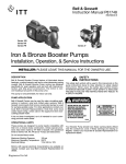
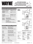
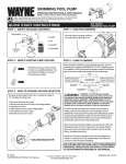
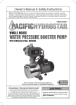
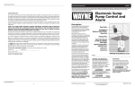
PC1 and PC2 Series Operating Instructions & Parts Manual Please read and save these instructions. Read carefully before attempting to assemble, install, operate or maintain the product described. Protect yourself and others by observing all safety information. Failure to comply with instructions could result in personal injury and/or property damage! Retain instructions for future reference. Self-Priming Transfer Pumps Table of Contents Unpacking General Safety Information Description . . . . . . . . . . . . . . . . . . . . . . 1 Inspect this unit before it is used. Occasionally, products are damaged during shipment. If the pump or components are damaged, return the unit to the place of purchase for replacement. Failure to do so could result in serious injury or death. CALIFORNIA PROPOSITION 65 Unpacking . . . . . . . . . . . . . . . . . . . . . . 1 Safety Guidelines . . . . . . . . . . . . . . . . . 1 General Safety Information . . . . . . . . 1 Installation . . . . . . . . . . . . . . . . . . . . . . 2 Operation . . . . . . . . . . . . . . . . . . . . . . . 2 Maintenance . . . . . . . . . . . . . . . . . . . . 3 READ & FOLLOW ALL INSTRUCTIONS Troubleshooting Chart . . . . . . . . . . . . .4 SAVE THESE INSTRUCTIONS DO NOT DISCARD Replacement Part Information . . . . . 6-7 Warranty . . . . . . . . . . . . . . . . . . . . . . . . 8 Description These self-priming transfer pumps are designed to easily transfer water from one point to another. Model PC1, 12 Volt Transfer Pump is convenient when normal power is not readily available. Typical applications include removing water from pool covers, clogged drains, stock tanks, water basins, boats, cisterns, etc. Model PC2, 115 Volt Transfer Pump is great for household usage. Typical applications include removing water from waterbeds, clogged sinks, basements, etc. Note: Do NOT use PC2 in pool areas. The motors on both models PC1 and PC2 are nonsubmersible. Safety Guidelines This manual contains information that is very important to know and understand. This information is provided for SAFETY and to PREVENT EQUIPMENT PROBLEMS. To help recognize this information, observe the following symbols. Danger indicates an imminently hazardous situation which, if not avoided, WILL result in death or serious injury. Warning indicates a potentially hazardous situation which, if not avoided, COULD result in death or serious injury. Caution indicates a potentially hazardous situation which, if not avoided, MAY result in minor or moderate injury. This product or its power cord may contain chemicals known to the State of California to cause cancer and birth defects or other reproductive harm. Wash hands after handling. GENERAL SAFETY Do not submerge motor or allow motor to be exposed to water. Personal injury and/or death could result. Keep pump and power cords away from liquids. Model PC1 becomes very hot during operation. Do not pump gasoline or other explosive liquids. Do not operate pump where flammable or explosive fumes or gases are present as a fire or explosion could result. Pump should only be used to pump clear water. Do not run pump dry. 1. Read all instructions before operation. MANUAL 2. Protect electrical cord from sharp objects, hot surfaces, oil and chemicals. Avoid kinking the cord and replace damaged cords immediately. This pump has been evaluated for use with water only. Notice indicates important information, that if not followed, may cause damage to equipment. NOTE: Information that requires special attention. REMINDER: Keep your dated proof of purchase for warranty purposes! Attach it to this manual or file it for safekeeping. © 2009 Wayne Water Systems For parts, product & service information visit www.waynepumps.com 321207-001 08/12 Operating Instructions and Parts Manual Installation Models PC1 and PC2 include a six foot long suction hose, a water suction attachment, and a replacement parts kit which includes: impeller, gasket, shaft seal, and two motor brushes (PC2 only, brushes are not designed to be replaced on PC1). Always disconnect power source before attempting to install, service, or maintain the pump. Never handle a pump with wet hands or when standing on wet or damp surface or in water. Fatal electrical shock could occur. 1. A ground fault circuit interrupter (GFCI) is required for Model PC2. Risk of electrical shock! This pump is supplied with a grounding conductor and grounding type attachment plug. A grounded receptacle in conformance with current NEC and local codes must be used (See Figure 1). Do not use model PC2, 115 V Transfer Pump in swimming pool areas. 2. Model PC1 operates on 12V DC only. Model PC2 operates on 115V only. Voltage and current of power supply must match the requirements of the pump. Model PC1 has color-coded battery clamps for 12V operation. Model PC1 requires 14 amps at 12 VDC. 3. Never use an extension cord to power this unit. Risk of fatal electrical shock. Never cut off the round grounding prong. Cutting the cord or plug will void the warranty and make the pump inoperable. 4. Use a strainer when pumping from a creek, pond, or source where foreign objects may be sucked into the pump. The strainer should prevent solids from entering the inlet line. 5. A regular garden hose may be used as a discharge line. 6. The inlet or suction hose should not be longer than 15 feet; and the vertical distance between the pump and the water level should not be any higher than 10 feet. The maximum discharge height is 30 feet. 7. At times, an overload due to overheating, low voltage, jammed impeller, etc. may shut the pump off. Unplug or turn off the pump and wait at least ten minutes. The pump will cool and automatically reset. (Model PC2 only) 8. Motor should never be operated for more than 2 hours continuously. Critical heating can occur and might severely damage the pump and void warranty. Operation 1. Add 1 tablespoon of vegetable oil to both inlet and outlet to prime. Attach included 6 foot suction hose to inlet of pump. Attach garden hose to outlet of pump. There must be a gasket in place to insure that these connections are airtight, otherwise the pump will not prime. 2. Connect water suction attachment to the open end of inlet hose and place below water surface. (Water suction attachment is optional for both PC1 and PC2 models.) The water suction attachment is designed to fit the male end of a garden hose. Place the water suction attachment as near as possible to the middle of the water that is to be pumped. 3. Examine the inlet and outlet hoses to insure there are no blockages, kinks or bends. Place switch in “OFF” position before connecting or disconnecting battery terminal clamps. www.waynepumps.com 2 IMPORTANT BATTERY INFORMATION Be certain that the area around the batteries is well ventilated. Before servicing the batteries, blow away gasses by waving a piece of cardboard near the batteries. Dangerous hydrogen gas can be released from batteries while charging. Sparks can ignite the gas in an enclosed space. Wear safety goggles when connecting batteries. Battery connections should be made in a well-ventilated area. Working in the vicinity of lead acid batteries can be dangerous. Before making connections or servicing the batteries, read and follow instructions in all applicable instruction manuals. To reduce the risk of battery explosion, follow the instructions in this manual and those published by the battery manufacturer, as well as those of any other equipment used in the surrounding area. An assistant should be present or close enough to come to your aid in the event of an emergency. Have a reliable source of fresh water and soap nearby in case battery acid contacts clothing, skin or eyes. Wear eye and clothing protection when working around lead acid batteries. Avoid touching your eyes when working around lead acid batteries. If battery acid contacts your eye(s), flush with cold running water for 20 minutes and seek immediate medical attention. If acid contacts your skin or clothing, wash immediately with soap and water. Never smoke or allow a spark or flame in the vicinity of the battery. Avoid dropping metal tools on the battery posts because they may spark or short-circuit the system or battery, causing an explosion. PC1 and PC2 Series Operation (Continued) 12 VOLT WIRING DIAGRAM 4. Connect pump to power source, with pump in a dry location. Model PC1: Motor must be connected to a fully charged automotive tractor or marine type battery to operate. Grounding Plug TEST OUTLET BLACK CLAMP TO NEGATIVE TERMINAL INLET RED CLAMP TO POSITIVE TERMINAL + POS RESET NEG 12 VOLT DC BATTERY Figure 1 Connect the red clamp to the positive (+) type battery terminal. Connect the black clamp to the negative (-) type battery terminal. See 12V wiring diagram below (Figure 2). Model PC2: Plug into a 115 Volt AC 3-prong ground-type GFCI receptacle. Maintenance Always disconnect power source before attempting to install, service, or maintain the pump. IMPELLER REPLACEMENT These parts are designed to handle most clear, nonflammable liquids with slight amounts of abrasives. When impeller vanes become worn from use, or damaged due to pumping abrasive liquids or trash, pump performance will be reduced or prevented altogether. 1. Remove the four cover plate screws holding motor housing and pump housing together. Cover plate is now free and can be removed. 2. Inspect gasket and impeller for wear and damage. If there is any evidence of wear or damage, replace the part(s). 12 VOLT DC PUMP Figure 2 4. Reassemble gasket, cover plate, and cover plate screws. SHAFT SEAL REPLACEMENT Motor shafts are sealed with factory pre-lubricated lip-type seals which are good for the life of the pump. If the seal leaks, it is usually because the pump has handled abrasive liquids. If the motor shaft is scored (deep grooves), the complete pump must be replaced. 1. Remove and inspect impeller parts as specified in the impeller replacement instructions. Replace worn parts. 2. Remove two pump body mounting screws and slide pump body from motor. Pry out seal retaining ring and push worn shaft seal from inside of pump body. MOTOR BRUSH REPLACEMENT PC1 Model is equipped with lifetime brushes. Brush replacement is not necessary. Brushes for the PC2 pump should be inspected after 75 hours of operation and replace if worn. They must be replaced every 100 hours of operation. Service one brush at a time. 1) Disconnect pump from power supply. 2) Remove brush caps with screwdriver. 3) Remove old brush assembly. 4) Insert new brush assembly. 5) Replace brush caps. 3. Lubricate new seal with lightweight oil, push it into pump body with lip facing away from motor, and push in seal retaining ring. 4. Reassemble pump body onto motor with mounting screws. Follow steps 3 and 4 in Impeller Replacement. 3. Lubricate new impeller with white grease or lightweight oil and reinstall by aligning flat on impeller hub with flat on motor shaft. www.waynepumps.com 3 Operating Instructions and Parts Manual Troubleshooting Chart Symptom Pump will not start or run Pump will not prime or retain prime after operating Flow rate is too low Shaft seal leaks Possible Cause(s) Corrective Action 1. Blown fuse 1. If blown, replace with proper sized fuse or reset breaker 2. Low line voltage 2. Voltage of power supply must match the voltage of the pump 3. Worn brushes 3. Replace brushes (PC2 Only) 4. Impeller blocked 4. Remove blockage 5. Motor has overheated (Model PC2 only) 5. Disconnect from power supply and allow to cool (Minimum 10 minutes) 1. Air leak in suction line 1. Repair suction line by tightening inlet connection or replace 2. Impeller blocked 2. Remove blockage 3. Worn seal 3. Replace seal 4. Suction lift too high 4. Lower pump 5. Hose kinked or looped 5. Straighten hose 6. Fittings not tight 6. Tighten fittings 7. Suction hose out of water 7. Submerge suction hose end 8. Clogged inlet 8. Clean inlet 1. Inlet hose plugged or kinked 1. Clean or replace 2. Low line voltage 2. Voltage of power supply must match the voltage of the pump 1. Worn seal 1. Replace seal 2. Shaft grooved 2. Replace pump 3. Pump head loose on motor 3. Insure proper assembly and no obstruction, tighten bolts www.waynepumps.com 4 PC1 and PC2 Series Notes www.waynepumps.com 5 Operating Instructions and Parts Manual For Replacement Parts or Technical Assistance, Call 1-800-237-0987 Please provide following information: - Model number - Serial number (if any) - Part description and number as shown in parts list BATTERY TERMINAL CLAMPS Address any correspondence to: Wayne Water Systems 101 Production Drive Harrison, OH 45030 U.S.A. 12 VOLT POWER CORD POWER SWITCH ON/OFF BRUSH ASSEMBLY (PC2 Only) BRUSH CAP GROUNDING PLUG ROTATION IMPELLER SHAFT COVER PLATE RETAINING RING SHAFT SEAL WATER SUCTION ATTACHMENT GASKET Figure 3 – Replacement Parts Illustration for Self-Priming Transfer Pumps www.waynepumps.com 6 PC1 and PC2 Series Replacement Parts List for Self-Priming Transfer Pumps PC1 KITS Description Impeller & Seal Brush Kit Water Suction Attachment PC2 KITS Description Brush Impeller & Seal Brush Kit Water Suction Attachment Part No. 66062-002 -------66064-002 Part No. 66058-002 66060-002 66064-002 www.waynepumps.com 7 Operating Instructions and Parts Manual Limited Warranty For one year from the date of purchase, Wayne Water Systems (“Wayne”) will repair or replace, at its option, for the original purchaser any part or parts of its Sump Pumps or Water Pumps (“Product”) found upon examination by Wayne to be defective in materials or workmanship. Please call Wayne (800-237-0987) for instructions or see your dealer. Be prepared to provide the model and serial number when exercising this warranty. All transporta tion charges on Products or parts submitted for repair or replacement must be paid by purchaser. This Limited Warranty does not cover Products which have been damaged as a result of accident, abuse, misuse, neglect, improper installation, improper maintenance, or failure to operate in accordance with Wayne’s written instructions. THERE IS NO OTHER EXPRESS WARRANTY. IMPLIED WARRANTIES, INCLUDING THOSE OF MERCHANT ABILITY AND FITNESS FOR A PARTICULAR PURPOSE, ARE LIMITED TO ONE YEAR FROM THE DATE OF PURCHASE. THIS IS THE EXCLUSIVE REMEDY AND ANY LIABILITY FOR ANY AND ALL INDIRECT OR CONSE QUENTIAL DAMAGES OR EXPENSES WHATSOEVER IS EXCLUDED. Some states do not allow limitations on how long an implied warranty lasts, or do not allow the exclusions or limitations of incidental or consequential damages, so the above limitations might not apply to you. This limited warranty gives you specific legal rights, and you may also have other legal rights which vary from state to state. In no event, whether as a result of breach of contract warranty, tort (including negligence) or otherwise, shall Wayne or its suppliers be liable for any special, consequential, incidental or penal damages including, but not limited to loss of profit or revenues, loss of use of the products or any associated equipment, damage to associated equipment, cost of capital, cost of substitute products, facilities, services or replacement power, downtime costs, or claims of buyer’s customers for such damages. You MUST retain your purchase receipt along with this form. In the event you need to exercise a warranty claim, you MUST send a copy of the purchase receipt along with the material or correspondence. Please call Wayne (800-237-0987) for return authorization and instructions. DO NOT MAIL THIS FORM TO WAYNE. Use this form only to maintain your records. MODEL NO._________________ SERIAL NO.____________________________ INSTALLATION DATE_______________ ATTACH YOUR RECEIPT HERE www.waynepumps.com 8