1
Series 93
User’s Manual
1/16 DIN Microprocessor-Based
Auto-tuning Control
User Levels:
• New User . . . . . . . . . . . . . . . . . . . . . . . . . . .go to page 1.1
• Experienced User . . . . . . . . . . . . . . . . . . . . .go to page 2.1
• Expert user . . . . . . . . . . . . . . . . . . . . . . . . . .go to page 2.1
Installers:
• Installation . . . . . . . . . . . . . . . . . . . . . . . . . .go to page 2.1
• Wiring . . . . . . . . . . . . . . . . . . . . . . . . . . . . . .go to page 2.3
97
TOTAL
CUSTOMER
SATISFACTION
3 Year Warranty
ISO 9001
Registered Company
Winona, Minnesota USA
Watlow Controls
1241 Bundy Blvd., P.O. Box 5580, Winona, Minnesota USA 55987-5580
Phone: (507) 454-5300, Fax: (507) 452-4507 http://www.watlow.com
0600-0001-0000 Rev C
February 1999
Made in the U.S.A.
$10
Supersedes 0600-0001-0000 Rev B
Recycled Paper At Least 10% Postconsumer Waste
NOTE:
Details of a “Note”
appear here in the
narrow margin on
the left side of each
page.
çCAUTION:
Details of a
“Caution” appear
here in the narrow
margin on the left
side of each page.
Safety Information
We use note, caution and warning symbols throughout this book to draw your
attention to important operational and safety information.
A bold text “NOTE” marks a short message in the margin to alert you to an
important detail.
A bold text “CAUTION” safety alert appears with information that is important for protecting your equipment and performance. Be especially careful to
read and follow all cautions that apply to your application.
A bold text “WARNING” safety alert appears with information that is important for protecting you, others and equipment from damage. Pay very close
attention to all warnings that apply to your application.
ÓWARNING:
Details of a
“Warning” appear
here in the narrow
margin on the left
side of each page.
The safety alert symbol, ç, (an exclamation point in a triangle) precedes a
general CAUTION or WARNING statement.
The electrical hazard symbol, Ó, (a lightning bolt in a triangle) precedes an
electric shock hazard CAUTION or WARNING safety statement.
Technical Assistance
If you encounter a problem with your Watlow controller, review all of your configuration information for each step of the setup, to verify that your selections
are consistent with your applications. If the problem persists after checking
the above, you can get technical assistance from your local Watlow representative, or by dialing (507) 454-5300.
An applications engineer will discuss your application with you.
Please have the following information available when calling:
• Complete model number
• All configuration information
• User’s Manual
• Diagnostic Menu readings
Your Feedback
Your comments or suggestions on this manual are welcome, please send them
to: Technical Writer, Watlow Controls, 1241 Bundy Blvd., P.O. Box 5580,
Winona, MN 55987-5580, Phone: (507) 454-5300, Fax: (507) 452-4507. The
Series 93 User’s Manual is copyrighted by Watlow Winona, Inc., © February
1999, with all rights reserved. (1638)
How to Use This Manual
Watlow Series 93
TC Table of Contents
Chapter 1: Overview ......................................................... 1.1
General Description ................................................ 1.1
Chapter 2: Install And Wire The Series 93 .................... 2.1
Panel Cutout ............................................................2.1
Dimensions ..............................................................2.1
Installation Procedure ..............................................2.1
Wiring the Series 93 ................................................2.3
Power Wiring............................................................2.3
Sensor Installation Guidelines .................................2.4
Input Wiring .............................................................2.4
Output 1 Wiring ...................................................... 2.6
Output 2 Wiring ...................................................... 2.8
System Wiring Example .......................................... 2.9
Chapter 3: How To Use The Keys And Displays ............ 3.1
Keys, Displays and Indicator Lights ........................ 3.1
Chapter 4: How To Set Up The Series 93 ...................... 4.1
Setting the Input Type DIP Switch .......................... 4.1
Entering Setup Menu .............................................. 4.2
Setup Parameters ................................................... 4.3
Setup Menu Table ................................................... 4.5
Operation Parameters ............................................. 4.6
Operation Menu Table ............................................. 4.7
Chapter 5: How To Tune And Operate ........................... 5.1
Autotuning .............................................................. 5.1
Manual Tuning ........................................................ 5.2
Manual and Automatic Operation ............................ 5.3
Using Alarms .......................................................... 5.4
Error Code Messages ............................................. 5.5
Error Code Actions ...................................................5.6
Appendix ........................................................................ A.1
Noise and Installation Guidelines .............................A.1
Noise Sources .........................................................A.1
Decreasing Noise Sensitivity ...................................A.1
Eliminating Noise .................................................... A.2
Entering the Calibration Menu .................................A.3
Restoring Factory Calibration ................................. A.4
Calibration Menu .................................................... A.4
Calibration Procedures ........................................... A.5
Glossary ................................................................. A.9
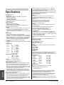
Specifications ....................................................... A.12
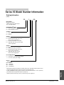
Model Number Information .................................. A.13
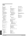
Index .................................................................... A.14
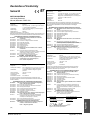
Declaration of Conformity.......................................A.15
Quick Reference ................................................... A.17
Watlow Series 93
Figures and Tables
Figures ...................................................... Page
Series 93 Input and Output Overview ..............................1.1
Series 93 Multiple Panel Cutout Dimensions .................2.1a
Series 93 Dimensions ....................................................2.1b
Mounting, Case Side View ............................................. 2.2a
Mounting Collar ..............................................................2.2b
Case Rear View and IP65 (NEMA 4X) Seal Example ..... 2.2c
Power Wiring .................................................................. 2.3
Thermocouple Sensor Input Wiring .............................. 2.4a
2- or 3-wire RTD Sensor Input Wiring .......................... 2.4b
0-5VÎ (dc) Process Sensor Input Wiring ..................... 2.5a
4-20mA Process Sensor Input Wiring ...........................2.5b
Output 1 Mechanical Relay Wiring ................................ 2.6a
Output 1 Solid-state Relay w/o Suppression Wiring ..... 2.6b
Switched DC Output 1 Wiring ....................................... 2.7a
4-20mA Process Wiring ............................................... 2.7b
Output 2 Mechanical Relay Wiring ................................ 2.8a
Output 2 Solid-state Relay w/o Suppression Wiring .....2.8b
Switched DC Output 2 Wiring ....................................... 2.8c
System Wiring Example .................................................. 2.9
Wiring Notes...................................................................2.10
Series 93 Keys and Displays ........................................... 3.1
DIP Switch Location and Orientation ............................ 4.1a
Input DIP Switches .........................................................4.1b
Entering the Setup Menu .............................................. 4.2a
The Setup Menu ........................................................... 4.2b
The Operation Menu ....................................................... 4.6
Autotuning at a 200°F Set Point ..................................... 5.1
Clearing an Alarm ........................................................... 5.4
Error Code Message ....................................................... 5.5
Entering the Calibration Menu ........................................ A.3
Calibration Menu ............................................................ A.4
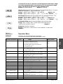
Tables ...................................................... Page
Input Ranges ................................................................. 4.5a
Setup Menu Prompts and Descriptions ......................... 4.5b
Operation Menu Prompts and Descriptions..................... 4.7
Quick Reference Sheet .........................................A.17-A.18
Table of Contents ■ i
Meet the Series 93 Team
TOTAL
CUSTOMER
SATISFACTION
3 Year Warranty
We stand behind our product and are committed to your total satisfaction.
Pictured below are some of the people at Watlow who have worked hard to
bring you one of the finest industrial temperature controllers available today.
Included in the photo are members of the development team, and representatives from our core manufacturing and customer service areas.
Front: Linda Florin, production; Nicole Smith, production; Trish Johnson,
production; Sarah Toraason, human resources.
Second Row: Steve Lubahn, marketing; Craig Dennis, marketing; Arlene
Fox, production; Shawn Cady, production; Kim Page, production; Roger
Ruehmann, applications engineer; Keith Ness, engineer.
Standing: Pam Obieglo, customer planner; Mark Wagner, engineer; Matt
Cyert, production; Dan Johnson, agency coordinator; Mary Koisti, production; Joe Seifert, shipping; Penny Roraff, production; Lisa Voelker, engineering technician; Cindy Panek, production; Dean McCluskey, engineer;
John Gabbert, technical editor; Tom Butler, test engineer; Sally Kotschevar,
purchasing.
ii ■ Table of Contents
Watlow Series 93
Overview of the Series 93
Overview
1
;; ;;
;;
;;
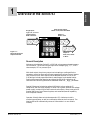
Single Input Type J, K, T, N or S
Thermocouple,
RTD or Process
Dual Control OutputPID or on-off, User Selectable
Output 1 Heat or Cool
93
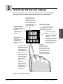
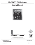
Figure 1.1 Series 93 Input and
Output Overview.
Output 2 Heat, Cool, Alarm
or None
General Description
Welcome to the Watlow Series 93, a 1/16 DIN microprocessor-based temperature controller. The 93 has a single input which accepts type J, K, T, N or S
thermocouple, RTD or process input.
With dual output, the primary output can be heating or cooling while the
secondary output can be a control output opposite the primary output (heat or
cool), alarm or none. Both outputs can be selected as either PID or on-off.
PID settings include proportional band, reset/integral, and rate/derivative.
Setting the proportional band to zero makes the Series 93 a simple on-off
controller with switching differential selectable under the [`HSC] parameter.
Special 93 features include the optional NEMA 4X rating, optional CE
compliance, dual four-digit displays in either red or green, optional low-voltage
power supply, autotuning for both heat and cool outputs, ramp to set point for
gradual warm-up of your thermal system, and automatic/manual capability
with bumpless transfer.
Operator-friendly features include automatic LED indicators to aid in
monitoring and setup, as well as a calibration offset at the front panel. The
Watlow Series 93 automatically stores all information in a non-volatile
memory.
Watlow Series 93
Overview ■ 1.1
Notes
Overview
1.2 ■ Overview
Watlow Series 93
2
Install and Wire the Series 93
NOTE:
Install and Wire
For rapid mounting,
use Greenlee 1/16
DIN punch, die, draw
stud, part number
5073941.7.
NOTE:
Measurements
between panel
cutouts are the minimum recommended.
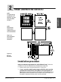
Figure 2.1a Series 93 Multiple
Panel Cutout
Dimensions.
Figure 2.1bSeries 93
Dimensions.
Installation procedure
Bold print denotes requirement for IP65 (NEMA 4X) seal. Follow this
procedure to mount the Watlow Series 93 temperature controller:
1. Make a panel cutout using the dimensions in Figure 2.1a.
2. If your controller model number begins with 93B, make sure the
rounded side of the external case gasket is facing the panel surface. Check to see that the gasket is not twisted, and is seated within the
case bezel flush with the panel. Place the case in the cutout. Make sure
the gasket is between the panel cutout and the case bezel.
Watlow Series 93
Install and Wire ■ 2.1
0 to 0.483 mm space
(0 to 0.019 in.)
Panel
Ridges
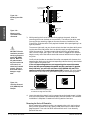
Figure 2.2a -
Bezel
Tabs
Mounting Case Side
View.
Mounting Collar
External Gasket
Install and Wire
Teeth
Figure 2.2b Mounting Collar
Cross Section with
offset teeth.
ç
CAUTION: Follow the
installation procedure
exactly to guarantee a
proper IP65 (NEMA
4X) seal. Make sure
the gasket between
the panel and the rim
of the case is not
twisted and is seated
properly. Failure to
do so could result in
damage to equipment.
3. While pressing the front of the case firmly against the panel, slide the
mounting collar over the back of the controller. The tabs on the collar must
line up with the mounting ridges on the case for secure installation. See
Figure 2.2a. Slide the collar firmly against the back of the panel getting it as
tight as possible.
To ensure a tight seal, use your thumb to lock the tabs into place while pressing the case from side to side. Don’t be afraid to apply enough pressure to
install the controller. The tabs on each side of the collar have teeth which
latch into the ridges. See Figure 2.2b. Each tooth is staggered at a different
height, so only one of the tabs on each side are ever locked into the ridges at
any time.
Confirm that the tabs on one side of the collar correspond with those on the
opposite side. Make sure the two corresponding tabs are the only ones locked
in the ridges at the same time.
If the corresponding tabs are not supporting the case at the same
time, and the space between the panel and the case bezel is greater
than .019 inch, you will will not have a IP65 (NEMA 4X) seal. This
applies to units with models designated 93B. However, all units should
be mounted in this fashion to guarantee integrity of the mounting system.
Figure 2.2c Case Rear View and
IP65 (NEMA 4X) Seal
Example.
IP65 (NEMA 4X) Seal Example.
Make sure that the two corresponding tabs
are locked in the ridges at the same time.
4. Insert the controller chassis into its case and press the bezel to seat it. Make
sure the inside gasket is also seated properly and not twisted. The hardware
installation is complete. Proceed to the wiring section from here.
Removing the Series 93 Controller
When removing the mounting collar, we suggest using a thin tool such as a
putty knife or screwdriver to pry gently under each of the six tabs to disengage the teeth. Then rock the collar back and forth until it can be easily
pulled off the case.
2.2 ■ Install and Wire
Watlow Series 93
Wiring the Series 93
WARNING: To avoid
electric shock, use
National Electric
Code (NEC) safety
practices when
wiring and connecting this unit to a
power source and to
electrical sensors or
peripheral devices.
Failure to do so could
result in injury or
death.
The Series 93 wiring is illustrated by model number option.
Check the unit sticker on the controller and compare your model
number to those shown here and also the model number breakdown in the Appendix of this manual.
All outputs are referenced to a de-energized state. The final
wiring figure is a typical system example.
When you apply power without sensor inputs on the terminal
strip, the Series 93 displays [----] in the upper display, and
[```0] in the lower display, except for 0-5VÎ (dc) or 4-20mA
process input units. Press the ˆInfinity key twice, and [ER`7]
is displayed for one second. This error indicates an open sensor
or an analog-to-digital error. All wiring and fusing must conform to the National Electric Code and to any locally applicable
codes as well.
NOTE:
Taking the unit out of
the case is not a normal operating condition and should only
be done by a qualified maintenance
installation technician. Power to the
case should be disconnected before
removing or
installing the controller into its case.
Power Wiring
High Voltage
100 to 240Å (ac), nominal (85 to 264 actual) 93_ _-1_ _ 0 - 00_ _
Low Voltage
12 to 24V‡ (ac/dc) 93_ _- 1_ _ 1 - 00_ _
∫
WARNING: The case
terminals may still
carry live voltage
when the unit is
removed.
∫
WARNING:
Irreversible damage
will occur if high
voltage is applied to
the low voltage unit.
Watlow Series 93
Figure 2.3 – Power Wiring.
Install and Wire ■ 2.3
Install and Wire
∫
∫ç
Install and Wire
WARNING: To avoid electric shock and damage to
property and equipment,
use National Electric
Code (NEC) safety practices when wiring and
connecting this unit to a
power source and to
electrical sensors or
peripheral devices.
Failure to do so could
result in injury or death.
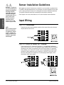
Sensor Installation Guidelines
We suggest you mount the sensor at a location in your process or system where
it reads an average temperature. Put the sensor as near as possible to the material or space you want to control. Air flow past this sensor should be moderate.
The sensor should be thermally insulated from the sensor mounting.
See Chapter 4 for more information on DIP switch location and orientation.
Input Wiring
Figure 2.4a – Thermocouple
NOTE:
When an external device
with a non-isolated circuit common is connected to the 4-20mA or dc
output, you must use an
isolated or ungrounded
thermocouple.
Extension wire for thermocouples must be of the same alloy as the thermocouple itself to limit errors.
Figure 2.4b – RTD (2- or 3-Wire) 100Ω Platinum
There could be a + 2°F input error for every 1Ω of lead length resistance
when using a 2-wire RTD. That resistance, when added to the RTD element
resistance, will result in erroneous input to the instrument. To overcome
this problem, use a 3-wire RTD sensor, which compensates for lead length
resistance. When extension wire is used for a 3-wire RTD, all wires must
have the same electrical resistance (i.e. same gauge, same length, multistranded or solid, same metal).
2.4 ■ Install and Wire
Watlow Series 93
NOTE:
Successful installation requires four
steps:
Figure 2.5a – 0-5VÎ (dc) Process
Input impedance: 10kΩ
• Choose the controller’s hardware
configuration and
model number
(Appendix);
• Install and wire the
controller (Chapter
Two);
• Configure the controller (Chapters
Three, Four and Five).
Install and Wire
• Choose a sensor
(Chapter Two and
Appendix);
Figure 2.5b – 4-20mA Process
Input impedance: 5Ω
ç
WARNING: To avoid
damage to property
and equipment,
and/or injury or loss
of life, use National
Electric Code (NEC)
standard wiring practices to install and
operate the Series 93.
Failure to do so could
result in such damage, and/or injury or
death.
Figure 2.5c – 4-20mA Process: 2-Wire Transmitters
NOTE:
When an external
device with a nonisolated circuit common is connected to
the 4-20mA or dc output, you must use an
isolated or ungrounded thermocouple.
ç
CAUTION: Process
input does not have
sensor break protection. Outputs can
remain full on.
Watlow Series 93
Install and Wire ■ 2.5
NOTE:
Successful installation
requires four steps:
• Choose the controller’s
hardware configuration
and model number
(Appendix);
• Choose a sensor
(Chapter Two and
Appendix);
Install and Wire
• Install and wire the
controller (Chapter Two);
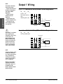
Output 1 Wiring
Figure 2.6a – Mechanical Relay Without Contact Suppression
93_ _- 1 D _ _- 00 _ _
Form C, 5A
Minimum load current:
100mA @ 5VÎ (dc)
• Configure the controller (Chapters Three,
Four and Five).
ç
WARNING: To avoid damage to property and
equipment, and/or injury
or loss of life, use
National Electric Code
(NEC) standard wiring
practices to install and
operate the Series 93.
Failure to do so could
result in such damage,
and/or injury or death.
8
NC
9
COM
Fuse
L1
10 NO
External
Load
Customer-supplied
Quencharc
L2
Figure 2.6b – Solid-state Relay Without Contact Suppression
93_ _- 1 K _ _- 00 _ _
0.5A (ac loads only)
Customer-supplied
Quencharc
L2
External
Load
8
10
Fuse
L1
NOTE:
Switching inductive loads
(relay coils, solenoids,
etc.) with the mechanical
relay, switched dc or
solid-state relay output
options requires use of
an R.C. suppressor.
Watlow carries the R.C.
suppressor Quencharc
brand name, which is a
trademark of ITW
Paktron. Watlow Part No.
0804-0147-0000.
2.6 ■ Install and Wire
Watlow Series 93
Successful installation requires four
steps:
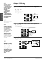
Figure 2.7a – Switched DC
93_ _- 1 C _ _- 00 _ _
• Choose the controller’s hardware
configuration and
model number
(Appendix);
• Choose a sensor
(Chapter Two and
Appendix);
• Install and wire
the controller
(Chapter Two);
• Configure the
controller (Chapters
Three, Four and
Five).
NOTE:
9
+
10
-
External
Load
Install and Wire
NOTE:
Figure 2.7b – 4-20mA Process
93_ _- 1 F_ _- 00 _ _
Maximum load impedance: 800Ω
9
+
10
-
External
Load
When an external
device with a nonisolated circuit common is connected to
the 4-20mA or dc
output, you must use
an isolated or ungrounded thermocouple.
Watlow Series 93
Install and Wire ■ 2.7
NOTE:
Successful installation
requires four steps:
• Choose the controller’s
hardware configuration
and model number
(Appendix);
• Choose a sensor
(Chapter Two and
Appendix);
Install and Wire
• Install and wire the
controller (Chapter Two);
Output 2 Wiring
Figure 2.8a – Mechanical Relay Without Contact Suppression
93_ _- 1 _ D _ - 00_ _
Form C, 5A
Minimum load current:
100mA @ 5VÎ (dc)
Fuse
6 COM
NC 1
L1
7 NO
• Configure the controller (Chapters Three,
Four and Five).
External
Load
L2
NOTE:
Customer-supplied
Quencharc
Output is in open state in
Alarm Condition.
Figure 2.8b – Solid-state Relay Without Contact Suppression
NOTE:
93_ _- 1_ K _- 00_ _
Switching inductive loads
(relay coils, solenoids,
etc.) with the mechanical
relay, switched dc or
solid-state relay output
options requires use of an
R.C. suppressor.
0.5A (ac loads only)
Watlow carries the R.C.
suppressor Quencharc
brand name, which is a
trademark of ITW Paktron.
Watlow Part No. 08040147-0000.
1
L1
Fuse
7
External
Load
L2
Customer-supplied
Quencharc
Figure 2.8c – Switched DC
93_ _- 1_ C _ - 00_ _
ç
7 to 10V
2.8 ■ Install and Wire
94Ω
unregulated
7
WARNING: To avoid damage to property and equipment, and/or injury or loss
of life, use National
Electric Code (NEC) standard wiring practices to
install and operate the
Series 93. Failure to do so
could result in such damage, and/or injury or
death.
(dc)
V+
6 +
-
External
Load
6
V—
7
Internal Circuitry
Watlow Series 93
WARNING: To avoid
damage to property
and equipment,
and/or injury or loss
of life, use National
Electric Code (NEC)
standard wiring
practices to install
and operate the
Series 93. Failure to
do so could result in
such damage, and/or
injury or death.
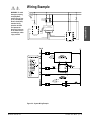
Wiring Example
L1
120VÅ (ac)
L2
Earth Ground
High Limit
Mechanical
Controller
Fuse
11
Coil
12
2
1
1 (-)
DIN-a-mite
2 (+) DA1C-1624-C000
3 (+)
9 (+)
5 (-)
4
3
11
Heater
12
10 (-)
93BB-1CA0-00RR
Rear View
Limit Sensor
3+
9
Process Sensor
5-
10
94BB-1DA0-00RR
Limit Controller
Figure 2.9 - System Wiring Example.
Watlow Series 93
Install and Wire ■ 2.9
Install and Wire
ç∫
∫ç
Install and Wire
WARNING: To avoid electric shock and damage to
property and equipment,
use National Electric
Code (NEC) safety practices when wiring and
connecting this unit to a
power source and to electrical sensors or peripheral devices. Failure to do
so could result in injury
or death.
Wiring Notes
Sketch in your application on this page or a copy of it. See the
wiring example in this chapter.
ç
WARNING: Install high or
low temperature limit
control protection in systems where an over temperature fault condition
could present a fire hazard or other hazard.
Failure to install temperature limit control protection where a potential
hazard exists could result
in damage to equipment,
property and injury to personnel.
∫
WARNING: All wiring and
fusing must conform to
the National Electric Code
NFPA70. Contact your
local board for additional
information. Failure to
observe NEC safety
guidelines could result in
injury to personnel or
damage to property.
Figure 2.10 - Wiring Notes.
2.10 ■ Install and Wire
Watlow Series 93
3
How to Use the Key and Displays
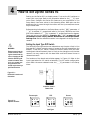
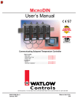
After 60 seconds with no key presses, the controller reverts to the default display —
the process value in the upper display and the set point in the lower display.
Advance Key: Press to
step through the
Operations, Setup and
Calibration Menus.
In the Auto mode, new
data is self-entering in five
seconds.
Up-arrow and Downarrow Keys: Increases or
decreases the value of the
displayed parameter.
• Press lightly to increase
or decrease the value by
one.
• Press and hold down to
increase or decrease the
displayed value at a rapid
rate. New data will selfenter in five seconds, or
can be entered by
pressing the Advance
Key.
• Press both
simultaneously for three
seconds to enter the
Setup Menu. The [`LOC]
parameter appears.
• Continue pressing both
keys to enter the
Calibration Menu.
Output 1 Indicator Light: Lit
when Output 1 is energized.
93
Output 2 Indicator Light: Lit
when Output 2 is active. This
output can be configured as
a control or alarm output.
% Percent Power Indicator
Light
• Lit: the controller is in Manual
operation. Press the ˆInfinity
key twice to enter Automatic
operation.
• Blinking: press the ˆInfinity
key to toggle between Auto and
Manual. Returns to its previous
state and stops blinking if the
ˆInfinity key is not pressed
within five seconds.
Infinity Key
• Press once to clear any
latched alarms. It also
disables the deviation alarm
output if silencing is enabled.
• Press again within five
seconds to change from Auto
to Manual or vice versa. While
in Manual mode, percent
power is in the lower display.
Figure 3.1 - Series 93 Keys and Displays.
Watlow Series 93
Keys and Displays ■ 3.1
Keys and Displays
Lower Display: Indicates
the set point, output value,
parameters for data in the
upper display, or error and
alarm codes.
• To set to blank: set
[`dSP] to [`Pro] in the
Setup Menu.
Upper Display: Indicates
the process value, actual
temperature, operating
parameter values or an open
sensor. When powering up,
the Process display will be
blank for five seconds.
• To set to blank: set [`dSP]
to [`SEt] in the Setup
Menu.
Notes
Keys and Displays
3.2 ■ Keys and Displays
Watlow Series 93
4
How to Set Up the Series 93
Setting up the Series 93 is a simple process. First set the DIP switches to
match your input type. Refer to the orientation below for the [``In] Input
value. Next, configure the Series 93's features to your application in the
Setup Menu, then enter values in the Operating Menu. Both tasks use the
‰Advance key to move through the menus and the Up-arrow/Down-arrow
keys to select data.
Before entering information in the Setup Menu, set the [`dFL] parameter. If
[``SI] is selected, °C, proportional band in % of span, derivative and integral are the defaults. If [``US] is selected, °F, proportional band in degrees,
reset and rate are the defaults. Changing the [`dFL] prompt will set
parameters to their factory default. Document all current parameter
settings first. See the calibration section in the Appendix to change this parameter.
WARNING:
Remove power from the
controller before removing the chassis from the
case or changing the DIP
switches. Removing the
controller from the chassis is not a normal operating condition and
should only be done by a
qualified technician.
Setting the Input Type DIP Switch
The Series 93 input type can be user selectable at any time via a Dual In-line
Package (DIP) switch inside the control, located on the left (viewed from the
bottom). To set the DIP switch, remove the control chassis from the case.
Holding each side of the bezel, press in firmly on the side grips until the tabs
release. You may need to rock the bezel back and forth several times to
release the chassis.
The locations of the board and switches appear in Figure 4.1. Refer to the
input types below for DIP switch orientation. The DIP switch configuration
must match the sensor selected under the [``In] parameter in the Setup
Menu.
Figure 4.1a DIP Switch Location and
Orientation.
Controller Chassis Bottom View
Thermocouple
Figure 4.1b Input DIP Switches.
O 1
N
2
RTD
O 1
N
Process
2
O 1
N
2
Input Types
Watlow Series 93
Setup ■ 4.1
Setup
∫
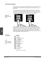
Entering the Setup Menu
The Operation Menu will appear as the default menu of the Series 93. The Setup
Menu displays the parameters that configure the Series 93's features to your
application.
Enter the Setup Menu by pressing the ¿Up-arrow and ¯Down-arrow keys simultaneously for 3 seconds. The lower display shows the [`LOC] Lock parameter, and the upper display shows its current level. All keys are inactive until you
release both keys. You can reach the Lock parameter from anywhere.
93
93
Figure 4.2a Entering the Setup
Menu.
Setup
Use the ‰Advance key to move through the menus and the ¿Up-arrow and
¯Down-arrow keys to select data. You will not see all parameters in this menu,
depending on the controller's configuration and model number. After stepping
through the menu it returns to the set point parameter under the Operation
Menu. If no keys are pressed for approximately 60 seconds, the controller returns
to the default display, Process over Set Point.
Figure 4.2b The Setup Menu.
‰
NOTE:
While in the Setup
Menu, all outputs are
off.
Setup Menu
[`LOC] Lock
[``In] Input
[`dEC] Decimal*
[`C_F] Celsius - Fahrenheit*
[``rL] Range Low
[``rH] Range High
[`Ot1] Output 1
[`HSC] Hysteresis Control
[`Ot2] Output 2
[`HSA] Hysteresis Alarm*
[`LAT] Latching*
[`SIL] Silencing*
[`rtd] RTD*
[`rP`] Ramping
[`rT`] Rate*
[`P`L] Power Limiting*
[`dSP] Display
* Parameter may not always appear.
4.2 ■ Setup
Watlow Series 93
Setup Parameters
Shaded parameters may not
appear, depending on the
controller’s configuration
and model number.
[`LOC}
NOTE:
Set the [`LOC] parameter
value as the final step in
programming the Series 93
controller to prevent locking
yourself out of the Operation
and Setup Menu during initial programming.
çCAUTION:
A process input does not
have sensor break protection
or bumpless transfer.
At the top of the Setup Menu the Series 93 displays the user level of operation
in the upper display and the [`LOC] parameter in the lower display.
Press the ‰Advance key and the value of the next parameter appears in the
upper display, and the parameter appears in the lower display.
Lock: Selects the level of operator lock-out as defined below.
Range: 0 to 4
Default: 0
[```0]: All operating parameters may be viewed or changed. Manual operation is permitted. When in manual operation, percent power is adjustable.
Bumpless transfer to manual mode will occur on sensor break.
[```1] The set point, process value and alarm settings are the only visible
parameters, set point is adjustable in this level. Manual operation and autotune are permitted. When in manual operation, percent power is adjustable.
Bumpless transfer to manual mode will occur on sensor break.
[```2] The set point, process value and alarm settings are the only visible
parameters, set point is adjustable in this level. Manual operation is permitted. When in manual operation, percent power is adjustable. Bumpless
transfer to manual mode will occur on sensor break.
çCAUTION:
[```3] The set point and process value are the only visible parameters, set
point is adjustable in this level. Manual operation is not permitted.
Bumpless transfer is defeated and outputs are disabled on sensor break.
Changing [``In] sets all
parameters to factory
defaults. Document all settings before changing this
parameter.
[```4] The set point and process value are the only visible parameters, set
point is not adjustable in this level of lock-out. Manual operation is not permitted. Bumpless transfer is defeated and outputs are disabled on sensor
break.
{``In}
Input: Selects the sensor input type. The internal DIP switch must also
match the {`In} parameter. See DIP switch orientation, and see input type
temperature ranges in the following chart.
Range: [```J], [```H] (K), [```t], [```n], [```S], [`rtd], [`r†d],
[`0-5], [`420]
Default: J
{`dEC}
Decimal: Selects the location of the decimal point for all process-related data.
This parameter only appears if the [``In] parameter is set to 0-5 or 420.
Make sure the internal DIP switch matches the [``In] parameter.
Range: 0, 0.0, 0.00
Default: 0
{`C-F}
{``rL}
Watlow Series 93
Celsius — Fahrenheit: Selects the units of temperature measurement for
the control. This parameter only appears if the [``In] parameter is set to a
thermocouple or RTD input. The default is dependent on the [`dFL] parameter located in the Calibration Menu. Refer to the Appendix.
Range: [```C] or [```F]
If [`dFL] is set to [``SI]: Default: [```C]
If [`dFL] is set to [``US]: Default: [```F]
Range Low: Selects the low limit of the set point. Also used to scale the low
end of the process input. 0.0VÎ (dc) and 4mA represent [``rL] Range Low
for a process input. The process input is linearly scaled between [``rL] and
[``rH]. See the model number and specification in the Appendix for range
values, or refer to the following table.
Range: Sensor range low to [``rh] Range High
Default: Low limit of sensor type for a thermocouple or RTD. -500 for a
process input.
4.3 ■ Setup
Setup
NOTE:
{``rh}
Range High: Selects the high limit of the operating range. Also used to scale the
high end of the process input. 5.0VÎ (dc) and 20mA represent Range High [``rh] for
a process input. The process input is linearly scaled between [``rL] and [``rH]. See
the model number and specification information in the Appendix for your range values, or refer to the following table.
Range: Sensor range high to [``rL]
Default: High limit of sensor type for a thermocouple or RTD. 9999 for process input.
{`Ot1}
Output 1: Selects the action for the primary output in response to the difference
between set point and process variable. Select [``ht] (heat) for reverse acting or
select [``CL] (cool) for direct acting.
Range: [``ht], [``CL]
Default: [``ht]
{`HSC}
Hysteresis-Control: Selects the switching hysteresis for Output 1 and 2 when you
select 0 (on-off) under the [`Pb1] parameter and [`Ot2] is set to [`Con].
Range: 1 to 55, 0.1 to 5.5, 0.01 to 0.55°C/1 to 99, 0.1 to 9.9, 0.01 to 0.99°F
Default: 2, 0.2, 0.02°C/3, 0.3, 0.03°F
{`Ot2}
Output 2: Selects the output action for the secondary output.
Range: [`Con] Control mode opposite Output 1 (heat or cool)
[`PrA]
[``Pr]
[`dEA]
[``dE]
[``no]
Process alarm with alarm message displayed
Process alarm with no alarm message displayed
Deviation alarm with alarm message displayed
Deviation alarm with no alarm message displayed
None
Default: [`Con]
Setup
{`HSA}
Hysteresis - Alarm: Selects the switching hysteresis for Output 2 when [`Ot2] is
an alarm. Appears only if [`Ot2] is not set to [`Con] or [``no]. See the Operation
Menu for [`Pb1].
Range: 1 to 5555, 0.1 to 555.5, 0.01 to 55.5°C/1 to 9999, 0.1 to 999.9, 0.01 to 99.99°F
Default: 2, 0.2, 0.02°C/3, 0.3, 0.03°F
{`LAt}
Latching: Selects whether the alarm is latching or non-latching. Latching alarms
must be cleared by pressing the ˆInfinity key before the alarm output will reset.
Selecting non-latching will automatically reset the alarm output when the condition
clears. Appears only if [`Ot2] is not set to [`Con] or [``no].
Range: [`LAt] or [`nLA]
Default: [`nLA]
{`SIL}
Silencing: Selects alarm silencing (inhibit) for the alarm. Appears only when [`Ot2]
is set to [`dEA] or [``dE]. For more information see Chapter 5.
Range: [``On] or [`OFF]
Default: [`OFF]
{`rtd}
RTD: Selects the RTD calibration curve for RTD inputs. Will not appear unless
[``In] is set to [`rtd] or [`r†d]. [`JIS] is 0.003916Ω/Ω°C, [`Din] is
0.003850Ω/Ω°C.
Range: [`din] or [`JIS]
Default: [`din]
{`rP`}
Ramping: Choose [`Str], and the set point ramps at the selected rate in °/hr. from
the process (actual) temperature to the set point, when power is applied to the controller (start up). It will not ramp with a set point change. [`On] is the same as
[`Str], but ramps with a set point change. It ramps from the previous set point to a
new one at the selected ramp rate. Select [`OFF] for no ramping action. When ramping, the lower display alternately flashes [``rP]. The set point displayed is the
desired end set point. The ramping set point is not shown. Entering the Setup Menu
or manual operation disables the outputs and ramp. Once you exit either one, the
Series 93 controls to the last entered set point.
Range: [`Str], [``On], [`OFF]
Default: [`OFF]
{``rt}
Rate: Selects the ramping rate in degrees per hour. Will not appear if [``rP] is set
to [`OFF].
Range: 0 to 9999
Default: 100°/hr.
4.4 ■ Setup
Watlow Series 93
[`P`L]
Power Limiting: The power limiting function in % power for heat only. Power
Limiting will function if [`pb1] is set to [```0].
Range: Dependent on output type. 0 to100
Default: 100
{`dSP}
Display: Selects which displays are active or viewable. Five seconds after selected, the appropriate display goes blank. Press ‰Advance, ¿Up-arrow or ¯Downarrow to override this feature and cause the current value to be displayed for 5
seconds.
Range: [`nor] Normal displays
Default: [`nor]
[`SEt] Set Point - lower display only
[`Pro] Process - upper display only
Table 4.5a Input Ranges.
NOTE:
Document your Setup
Menu parameters.
Do not mark any values
here; make photocopies
instead.
Table 4.5b Setup Menu Prompts and
Descriptions.
Value
Sensor Range Low
Sensor Range High
[```J]
[```H]
[```t]
[```n]
[```S]
[`rtd] (1°)
[`r†d] (0.1°)
[`420]
0°C/32°F
-200°C/-328°F
-200°C/-328°F
0°C/32°F
0°C/32°F
-200°C/-328°F
-128.8°C/-199.9°F
4mA/-999 units
750°C/1382°F
1250°C/2282°F
350°C/662°F
1250°C/2282°F
1450°C/2642°F
700°C/1292°F
537.7°C/999.9°F
20mA/9999 units
[`0-5]
0VÎ (dc)/-999 units
5VÎ (dc)/9999 units
Setup Menu
Range
Factory Default
Appears If:
[`LOC]
0 to 4
0
[``In]
[```J]
DIP switch selectable.
[`dEC]
[```J], [```H], [```t], [```n], [```S],
[`rtd], [`r†d], [`0-5], [`420]
0, 0.0, 0.00
0
[``In] is set to [`0-5] or [`420]
[`C_F]
[```C] or [```F]
Dependent on [`dFL]
[``In] is set to [```J], [```H],
[```t],[```n],[```S], [`rtd], or
[`r†d]
[``rL]
[``rL] to [``rh]
Input dependent
[``rh]
``rh] to [``rL]
Input dependent
[`Ot1]
[``ht] or [``CL]
[``ht]
[`HSC]
1 to 55, 0.1 to 5.5, 0.01 to 0.55°C
1 to 99, 0.1 to 9.9, 0.01 to 0.99°F
2, 0.2, 0.02°C
3, 0.3, 0.03°F
[`Ot2]
[`Con] Control
[`PrA] Process alarm
[``Pr] Process with no alarm message
[`dEA] Deviation alarm
[``dE] Deviation with no alarm message
[``no] None
[`Con]
[`HSA]
1 to 5555, 0.1 to 555.5, 0.01 to 55.55°C
1 to 9999, 0.1 to 999.9, 0.01 to 99.99°F
2, 0.2, 0.02°C
3, 0.3, 0.03°F
[`Ot2] is not set to [`Con] or [``no]
[`LAt]
[`LAt] or [`nLA]
[`nLA]
[`Ot2] is not set to [`Con] or [``no]
[`SIL]
[``On] or [`OFF]
[`OFF]
[`Ot2] is set to [`dEA] or [``dE]
[`rtd]
[`JIS] or [`din]
[`din]
[``In] is set to [`rtd] or [`r†d]
[`rP`]
[`Str] Ramping on power up
[``On] Ramping to set point at all times
[`OFF] None
[`OFF]
[`rt`]
0 to 9999
100°/hr
[``rP] is not set to [`OFF]
[`P`L]
0 to 100
100
[`Ot1] or [`Ot2] is set to [``ht]
[`dsP]
[`nor] normal
[`SEt] Set Point (lower only)
[`Pro] Process (upper only)
[`nor]
Watlow Series 93
Setup ■ 4.5
Setup
Parameter
Input Type
Figure 4.6 The Operation Menu.
Operation Menu
‰
NOTE:
The upper display
will always return to
the process value
after 1 minute without key strokes.
NOTE:
Shaded parameters
may not appear,
depending on the
controller’s configuration and model
number.
[``SP}
Setup
{`Pb1}
{`Pb2}
Operation Menu
[``93] Control Set Point
[`Pb1] Proportional Band 1
[`rE1] Reset 1*
[`It1] Integral 1*
[`rA1] Rate 1*
[`dE1] Derivative 1*
[`Ct1] Cycle Time 1*
[`ALO] Alarm Low*
[`AHI] Alarm High*
[`Pb2] Proportional Band 2*
[`rE2] Reset 2*
[`It2] Integral 2*
[`rA2] Rate 2*
[`dE2] Derivative 2*
[`Ct2] Cycle Time 2*
[`CAL] Calibration Offset
[`AUt] Autotune
* Parameter may not always appear.
Operation Parameters
Set Point: Sets the operating set point for Output 1. Represents the process value
the system tries to achieve for Output 1. "SP" does not appear on the lower display.
The control set point value is displayed and can be incremented or decremented
without pressing the ‰Advance key. The lower display may be blank if [`dSP] is set
to [`Pro]. In a ramping mode, the lower display alternately flashes the desired end
set point and [``rP].
Proportional Band 1 and 2: A proportional band, expressed in degrees or % of
span, within which a proportioning function is active for Output 1 or 2. When
[`Pb1] is set to 0, the unit functions as an on-off control on Output 1 and 2.
[`Pb2] will not appear if [`Pb1] is set to 0 or [`Ot2] is not set to [`Con]. The
switching differential is determined by the [`HSC] parameter.
Range if [`dFL] is set to [``US]: [`Pb1]: 0 to 555°C/0 to 999°F/0 to 999 Units; 0.0
to 5.5°C/0.0 to 9.9°F/0.0 to 9.9 units, [`Pb2]: The same as [`Pb1] except lower
limit is 1 or 0.1. Defaults: [`Pb1] is set to 2.5°C/25°F
[`Pb2] is set to 25
Range if [`dFL] is set to [``SI]: 0 to 999.9% of span
Defaults: [`Pb1] is set to 3.0% [`Pb2] is set to 3.0%
{`rE1}
{`It1}
{`rE2}
{`It2}
Reset /Integral 1 and 2: An integral control action for Output 1 or 2 that automatically eliminates offset, or "droop," between set point and actual process temperature. [`rE1]/[`It1]: Will not appear if [`Pb1] is set to 0. [`rE2]/[`It2]:
Appears if [`Pb1] is not set to 0 and [`Ot2] is set to [`Con]. Either reset [``rE]
or integral [``It] will appear depending on how the [`dFL] parameter is set in
the Calibration Menu. See the Appendix.
Range if [`dFL] is set to [``US]: 0 to 9.99 repeats/minute Default: 0.00
Range if [`dFL] is set to [``SI]: 00.1 to 9.99 minutes per repeat Default: 0.00
{`rA1}
{`dE1}
{`rA2}
{`dE2}
Rate/Derivative 1 and 2: The rate (derivative) function for Output 1 or Output
2.
Eliminates overshoot on startup, or after the set point changes. [`rA1]/[`dE1]:
Will not appear if [`Pb1] is set to 0. [`rA2]/[`dE2]: Appears if [`Pb1] is not set
to 0 and [`Ot2] is set to [`Con]. Either rate [``rA] or derivative [``dE] appears
depending on how [`dFL] is set in the Calibration Menu.
Range if [`dFL] is set to [``US] or [``SI]: 0 to 9.99 minutes
Default: 0.0
{`Ct1}
{`Ct2}
Cycle Time 1 and 2: Time for a controller to complete one time-proportioned cycle
for Output 1 or Output 2; expressed in seconds. [`Ct1]: Will not appear if [`Pb1]
is set to 0, or Output 1 is 4-20mA. [`Ct2]: Will not appear if [`Pb1] is set to 0 or
[`Ot2] is not set to [`Con].
4.6 ■ Setup
Watlow Series 93
If a mechanical relay or contactor is switching power to the load, a longer
cycle time may be desirable to minimize wear on the mechanical components. Typical life of a mechanical relay is 100,000 cycles.
Range: 0.1 to 999.9 seconds
Default: 5.0 seconds
{`ALO}
Alarm Low: Represents the low process alarm or low deviation alarm. This parameter will not appear if [`Ot2] is set to no or [`Con].
Range if [`Ot2] is set to [`dEA] or [``dE]: -999 to 0
Default: -999
Range if [`Ot2] is set to [`PrA] or [``Pr]: [``rL] to [`AHI] Default: [``rL]
{`AHI}
Alarm High: Represents the high process alarm or high deviation alarm. This
parameter will not appear if [`Ot2] is set to [``no] or [`Con].
Range if [`Ot2] is set to [`dEA] or [``dE]: 0 to 999
Default: 999
Range if [`Ot2] is set to [`PrA] or [``Pr]: [`ALO] to [``rH] Default: [``rH]
{`CAL}
Calibration Offset: Adds or subtracts degrees from the input signal.
Range: -100°C to 100°C/-180°F to 180°F/-180 units to 180 units; or
-10.0°C to 10.0°C/-18.0°F to 18.0°F
Default: 0
{`AUt}
Autotune: Initiates an autotune.
Range: 0 is set to off, 1 is set to slow, 2 is set to medium, 3 is set to fast
Default: 0
Operation Parameters
[`Pb1]
Operation Menu
Document your Series 93 Operation Parameters.
Do not mark any values here; make photocopies instead.
Value
Range
If [`dFL] is set to [``US]:
0 to 555°C/0 to 999°F/0 to 999 Units
0 to 55.5°C/0 to 99.9°F/0 to 99.9 Units
0 is control. [`HSC] is set to switch differential
If [`dFL] is set to [``SI]:
0.0 to 999.9% of span
Factory Default
2.5°C
25°F
Setup
Table 4.7 Operation Menu
Prompts and
Descriptions.
3%
[`rE1]
0.00 to 9.99 repeats/minute
0.00 = No Reset. Won't appear if [`Pb1] is set to 0
or [`dFL] is set to [``SI].
0.00 repeats/minute
[`It1]
0.0 to 99.9 minutes/repeat. 0.00 = No Integral.
Won't appear if [`Pb1] is set to 0 or [`dFL] is set to [``US].
00.0 minutes/repeat
[`rA1]
0.00 to 9.99 minutes
0.00 = No Rate. Will not appear if [`Pb1] is set to 0
or [`dFL] is set to [``SI].
0.00 minutes
[`dE1]
0.00 to 9.99 minutes. 0.00 = No Derivative.
Won't appear if [`Pb1] is set to 0 or [`dFL] is set to [``US].
0.00 minutes
[`Ct1]
0.1 to 999.9
Won't appear if [`Pb1] is set to 0, or [`420].
5.0 seconds
[`Pb2]
Same as [`Pb1]. [`Pb2] lower limit = 1, 0.1, 0.01
[`rE2]
Same range as [`rE1].
[`It2]
Same range as [`It1].
[`rA2]
Same range as [`rA1].
[`dE2]
Same range as [`dE1].
[`Ct2]
Same range as [`Ct1].
[`ALO] Deviation [``dE]
Process [``Pr]
-999 to 0
[``rL] to [`AHI]
Will not appear if [`Ot2] is set to [``no] or [`Con].
-999
[``rL]
[`AHI] Deviation [``dE]
Process [``Pr]
0 to 999
[`ALO] to [``rH]
Will not appear if [`Ot2] is set to [``no] or [`Con].
999
[``rH]
[`CAL]
±100°C/±180°F/±180 Units
0
[`AUt]
0 to 3
0
Watlow Series 93
Setup ■ 4.7
Notes
Setup
4.8 ■ Setup
Watlow Series 93
5
How to Tune and Operate the Series 93
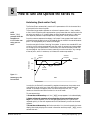
Autotuning (Heat and/or Cool)
The Series 93 can automatically tune the PID parameters to fit the characteristics
of your particular thermal system.
Set the [`HSC]
parameter under the
Setup Menu to
2°C/3°F before autotuning your controller.
The autotuning procedure operates on a thermal response value — slow, medium,
or fast. Use the slow thermal response when your process does not need to reach the
set point too rapidly, or if it usually does not often exceed the set point. A fast thermal response produces a rapid temperature change over a short period of time.
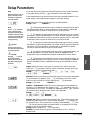
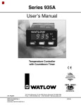
Once the autotune sequence has begun, the Output 1 heat proportional band is set
to 0 and the control goes into an on-off mode of control at 90% of the established set
point. The displayed set point remains unchanged.
Once the controller finishes "learning" the system, it returns to a standard PID control with the PID values automatically set as a result of autotuning. Autotune does
not change cycle time parameters. The controller can also be manually tuned. See
the next page for instructions on how to manually tune the controller. Any change
of the set point, while in autotune, re-initiates the autotune procedure.
Autotune
Begins
Autotune
Complete
Set Point
°Temperature
200
180
Process
100
90% of
Set Point
Tuning and Operating
NOTE:
Figure 5.1 Autotuning at a Set
Point of 200°F.
Time
In order for the Series 93 to successfully complete the autotune, the process must
cross 90% of the set point four times within 80 minutes after the autotune has
started. If this does not happen within the 80-minute time limit, the [``Pb]
remains at 0 and the controller functions in an on-off mode.
To start autotuning:
1. Press the ‰Advance key until the [`AUt] prompt appears in the data display.
2. Select a thermal response value using the ¿Up-arrow/¯Down-arrow
keys: 1 for a slow response, 2 for an average response and 3 for a system that
responds quickly. A thermal response value of 2 satisfactorily tunes most thermal
systems.
3. Press the ‰Advance key. While the controller is in the tuning mode, the lower
display alternately displays the normal information and the prompt [`AUt], at onesecond intervals.
Watlow Series 93
Tuning and Operating ■ 5.1
4. When tuning is complete, the displays return to their previous state and
[`AUt] reverts to 0. The Series 93 installs appropriate PID tuning parameters
and saves them in the non-volatile memory. If a mechanical relay or contactor is switching power to the load, a longer cycle time may be desirable
to minimize wear on the mechanical components. Typical life of a mechanical relay is 100,000 cycles.
To abort autotuning either reset the [`AUt] parameter to 0, press the
ˆInfinity key twice, or cycle power off and on. In all cases, aborting autotune
restores all values to those previous to autotuning.
Manual Tuning
Tune heating outputs at a
set point above ambient
temperature.
For optimum controller performance, tune the Series 93 to your thermal system. The tuning settings here are for a broad spectrum of applications; your
system may have somewhat different requirements. NOTE: This is a slow
procedure, taking from minutes to hours to obtain optimum value.
Tune cooling outputs at a
set point below ambient
temperature.
1. Apply power to the Series 93 and enter a set point. Set Operation parameters as follows: [``Pb] to [```1], [``rE] / [``It] to [`)00], [``rA] /
[``dE] to [`)00], [``Ct] to [``%0], [`CAL] to [```0], [`AUt] to [```0].
NOTE:
2. Proportional Band Adjustment: Gradually increase [``Pb] until the
upper display temperature stabilizes to a constant value. The process temperature will not be right on set point because the initial reset value is 0.00
repeats per minute. (When [``Pb] is set to 0; [``rE] / [``It] and [``rA] /
[``dE] are inoperative, and the Series 93 functions as a simple on-off controller.) The [`HSC] parameter determines the switching differential value.
3. Reset/Integral Adjustment: Gradually increase [``rE], or decrease
[``It] until the upper display temperature begins to oscillate or "hunt."
Then slowly decrease [``rE] or increase [``It] until the upper display stabilizes again near the set point.
Tuning and Operating
4. Cycle Time Adjustment: Set [``Ct] as required. Faster cycle times
sometimes achieve the best system control. However, if a mechanical contactor or solenoid is switching power to the load, a longer cycle time may be desirable to minimize wear on the mechanical components. Experiment until
the cycle time is consistent with the quality of control you want. [``Ct] will
not appear on units with a process output.
5. Rate/Derivative Adjustment: Increase [``rA] / [``dE] to 1.00 minute.
Then raise the set point by 11° to 17°C, or 20° to 30°F. Observe the system's
approach to the set point. If the load temperature overshoots the set point, increase [``rA] / [``dE] to 2.00 minutes.
Raise the set point by 11 to 17°C, or 20 to 30°F and watch the approach to the
new set point. If you increase [``rA] / [``dE] too much, the approach to the
set point is very sluggish. Repeat as necessary until the system rises to the
new set point without overshooting or approaching the set point too slowly.
6. Calibration Offset Adjustment: You may want your system to control to
a temperature other than the value coming from the input sensor. If so,
measure the difference between that temperature (perhaps at another point
in the system) and the process value showing in the upper display. Then
enter the calibration offset value you want. Calibration offset adds or subtracts degrees from the value of the input signal.
5.2 ■ Tuning and Operating
Watlow Series 93
Manual and Automatic Operation
To change from auto to manual operation, press the ˆInfinity key twice.
Manual operation provides open loop control of the outputs from a range of -100%
(full cooling) to 100% (full heating) power. The Series 93 allows a negative output
value only when [`Ot2] is set to [`Con]. Automatic operation provides closedloop on-off or PID control. When the operator transfers from a closed-loop to an
open loop, the Series 93 retains the power level from the closed-loop control,
referred to as bumpless transfer. When the Series 93 returns to closed-loop control, it restores the previous set point temperature.
The percent indicator light indicates auto or manual operation. When the percent
indicator light is on, the control is in manual operation and displays the percent
power value in the lower display. When the percent indicator light is off, it is in
automatic operation. Press the ˆInfinity key to flash the percent indicator light.
Press the ˆInfinity key again to complete the manual/automatic change.
When a sensor opens, the Series 93 switches from automatic to manual operation
if [`LOC] is set to 0, 1 or 2.
NOTE:
•If [`LOC] is set to 3 or 4, the Series 93 switches into manual operation at 0%
power (outputs disabled).
When transferring from auto to manual operation, the controller output(s)
remains stable ("bumpless," smooth transition). When transferring from manual
to automatic operation, the controller output(s) may change significantly. In
manual operation, the output value appears in the lower display; in automatic
operation, the set point appears.
Tuning and Operating
A process input does
not have sensor break
protection or bumpless transfer. Outputs
selected as [``ht]
(reverse acting) will
be full on if a sensor
break occurs.
•If [`LOC] is set to 0, 1 or 2 and the bumpless transfer conditions are met, the
Series 93 switches to manual operation at the last automatic power level. The
bumpless transfer conditions are: the process has stabilized within a ± 5%
power level for at least two minutes prior to sensor break provided the power
level is less than 75%.
Watlow Series 93
Tuning and Operating ■ 5.3
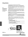
Using Alarms
The Series 93 has two alarm types, process and deviation.
NOTE:
When the alarm output is
de-energized, the N.O.
contact is open in the
alarm condition. The N.C.
contact is closed in the
alarm condition.
A process alarm sets an absolute temperature. When the process exceeds
that absolute temperature limit an alarm occurs. The process alarm set
points may be independently set high and low. Under the Setup Menu, select
the type of alarm output with the [`Ot2] parameter. [`PrA] sets a process
alarm with an alarm message displayed. [``Pr] sets a process alarm with no
alarm message displayed.
A deviation alarm alerts the operator when the process strays too far from
the set point. The operator can enter independent high and low alarm settings. The reference for the deviation alarm is the set point. Any change in
set point causes a corresponding shift in the deviation alarm. [`dEA] sets a
deviation alarm with an alarm message displayed. [``dE] sets a deviation
alarm with no alarm message displayed
Example: If your set point is 100°F, and a deviation alarm is set at +7°F as
the high limit, and -5°F as the low limit, the high alarm trips at 107°F, and
the low alarm at 95°F. If you change the set point to 130°F, the alarms follow
the set point and trip at 137°F and 125°F.
Latching: Both process and deviation alarms can be latching or non-latching. When the alarm condition is removed a non-latching alarm automatically clears the alarm output. You must manually clear a latching alarm
before it will disappear.
Flashing [``LO] or [``HI] in the lower display indicates an alarm when
[`Ot2] is set to [`PrA] or [`dEA]. The lower display alternately shows
information from the current parameter and the [``LO] or [``HI] alarm
message at one-second intervals. The alarm output is de-energized and the
Output 2 indicator light is lit.
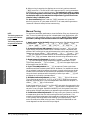
Tuning and Operating
To clear an alarm…
• First correct the alarm condition, then…
• If the alarm is latching…
Clear it manually; press the ˆInfinity key once as soon as the process temperature is inside the [`HSA] parameter alarm limit.
• If the alarm is non-latching…
The alarm clears itself automatically as soon as the process temperature is
inside the [`HSA] parameter alarm limit.
Auto-tuning at a Se
93
Autotune
Begins
Temperature
200
Figure 5.4 Clearing an Alarm.
5.4 ■ Tuning and Operating
180
Pro
90% of
Press once Clear a latched
and corrected
alarm.
Watlow Series 93
Alarm Silencing is available with the deviation alarm and has two uses:
When [`SIL] is selected as "on," the operator must manually disable the alarm
by pressing the ˆInfinity key once on initial power up (in either the latching or
non-latching mode). Alarm silencing disables the alarm output relay. However,
the Output 2 indicator light (also the lower display when [`Ot2] is set to [`dEA])
shows an alarm condition until the process value is within the “safe” region of the
deviation alarm band. Once the process value crosses into the “safe” region, both
a latching or a non-latching alarm is ready. Any future deviation outside this safe
band triggers an alarm.
Error Code Messages
NOTE:
An alarm display will
be masked by an
error condition or
when the controller is
in the Calibration or
Setup Menus.
Four dashes [----] in the upper display indicate a Series 93 error. The error
code is visible in the lower display.
93
Figure 5.5 Error Code Message.
ç
CAUTION:
Electrical noise or a
noise event, vibration
or excess environmental moisture or
temperature may
cause Series 93
errors to occur. If the
cause of an error is
not otherwise apparent, check for these.
Watlow Series 93
[`Er4] - Configuration error
The controller’s microprocessor is faulty; call the factory.
[`Er5] - Nonvolatile checksum error
The nonvolatile memory checksum discovered a checksum error. Unless a
momentary power interruption occurred while the controller was storing
data, the nonvolatile memory is bad. Call the factory.
[`Er6] - Analog-to-digital underflow error
The analog-to-digital circuit is underrange. An open or reversed polarity sensor is the most likely cause. Check the sensor; if the connection is good and
functions properly, call the factory. The analog-to-digital underrange voltage
is too low to convert an analog-to-digital signal. Make sure the [``In] parameter (Setup Menu) matches your sensor and the DIP switches are set
accordingly.
[`Er7] - Analog-to-digital overflow error
The analog-to-digital circuit is overrange. An open or reversed polarity sensor
is the most likely cause. Check the sensor; if the connection is good, and the
sensor functions properly, call the factory. The analog-to-digital overrange
voltage is too high to convert an analog-to-digital signal. Make sure the
[``In] parameter (Setup Menu) matches your sensor and the DIP switches
are set accordingly.
Tuning and Operating ■ 5.5
Tuning and Operating
[`Er2] - Sensor underrange error (applies only to RTD units)
The sensor input generated a value lower than the allowable signal range, or
the analog-to-digital circuitry malfunctioned. Enter a valid input. Make sure
the [``In] parameter (Setup Menu) and the DIP switch settings both match
your sensor.
Error Code Actions
• [`Er2], [`Er6], [`Er7] result in these conditions:
• If [`LOC] Lock is set to 0, 1 or 2:
…and the controller was in automatic operation when the error occurred, it
goes into manual (% power) operation. If the output power is less than 75%
power, and a <5% change in power occurred within the last two minutes, the
Series 93 switches into manual operation at the last automatic power level
(bumpless transfer). If the controller was in manual operation, it remains
there. Press the ˆInfinity key twice to see the error code. The alarm output
(if present) is in its alarm state (indicator lit). The upper display reads [---]. The lower display indicates the error code if the ˆInfinity Key is pressed
twice.
If the controller was operating with stable output values when the error occurred, it continues to operate at those levels on a % power basis. If output
values were not stable, the control outputs go to 0% power (off).
• If [`LOC] Lock is set to 3 or 4:
The controller remains in automatic operation and the outputs turn off. The
ˆInfinity and ‰Advance keys are inactive. The ¿Up-arrow/¯Down-arrow
keys may be pressed simultaneously to enter the Setup Menu. The alarm output (if present) is in its alarm state (indicator light lit). The upper display
reads [----]. The lower display indicates the error code if the ˆInfinity key
is pressed.
• To clear a corrected error…
• Press the ‰Advance key or turn the controller off and on.
Tuning and Operating
• [`Er4] and [`Er5] result in these conditions:
• The controller is in automatic operation with both outputs off.
• The alarm output, if present, are in their alarm state (de-energized with
the indicator lit).
• The upper display indicates the process value.
• The lower display indicates the error code.
• All keys are inactive.
• All Setup Menu parameters return to default values.
• The above conditions occur regardless of the value of [`LOC], or the
presence of the Setup or Calibration Menus.
• To clear a corrected error…
• Turn the controller off and on.
5.6 ■ Tuning and Operating
Watlow Series 93
A
Appendix
Noise and Installation Guidelines
For wiring guidelines, refer to the IEEE Standard No. 518-1982, available
from IEEE, Inc. 345 East 47th Street, New York, NY 10017.
Noise Sources
• Switches and relay contacts operating inductive loads such as motors,
coils, solenoids, and relays, etc.
• Thyristors or other semiconductor devices which are not zero crossoverfired (randomly-fired or phase angle-fired devices).
• All welding machinery and heavy current carrying conductors.
• Fluorescent and neon lights.
Decreasing Noise Sensitivity
• Physical separation and wire routing must be given careful consideration
in planning the system layout. For example, ac power supply lines should
be bundled together and physically kept separate from input signal lines
(sensor lines). A 305-mm (12-inch) minimum separation is usually effective. Keep all switched output signal lines (high power level) separate from
input signal lines (sensor lines). Cross other wiring at 90° angles whenever crossing lines is unavoidable.
• Shielded cables should be used for all low power signal lines to protect
them from magnetic and electrostatic coupling of noise. Some simple
pointers are:
◊ Whenever possible, run low-level signal lines unbroken from signal
source to the controller circuit.
◊ Connect the shield to the controller circuit common at the controller end
only. Never leave the shield unconnected at both ends. Never connect
both shield ends to a common or ground.
◊ Maintain shield continuity at daisy chain connection points by reconnecting the broken shield.
◊ Assume no electrostatic shielding when using the shield as a signal
return. If you must do this, use triaxial cable (electrostatically shielded
coaxial cable).
Watlow Series 93
Appendix ■ A.1
Appendix
• Look at the system layout; identify and locate electrical noise sources such
as solenoids, relay contacts, motors, etc. Route the wire bundles and cables
as far away as possible from these noise sources. Don't mount relays or
switching devices close to a microprocessor controller. Don't have phase
angle-fired devices in the same electrical enclosure or on the same power
line with the controller.
• Use twisted pair wire any time controller circuit signals must travel more
than two feet, or when you bundle them in parallel with other wires.
• Select the size or gauge of wire by calculating the maximum circuit current
and choosing the gauge meeting that requirement. Using greatly larger
wire sizes than required generally increases the likelihood of electrostatic
(capacitance) coupling of noise.
• Eliminate ground loops in the entire controller system. You can spot the
obvious loops by studying the "as-built" wiring diagram. There are also
not-so-obvious ground loops resulting from connecting internal circuit commons in the manufacturer's equipment.
• Do not daisy chain ac power (or return) lines, or output signal (or return)
lines to multiple controller circuits. Use a direct line from the power source
to each input requiring ac power. Avoid paralleling L1 (power lead) and L2
(return lead) to load power solenoids, contactors, and controller circuits. If
an application uses L1 (power lead) to switch a load, L2 (return lead) has
the same switched signal and could couple unwanted noise into a controller circuit.
• Tie all ground terminals together with one lead (usually green wire) tied to
ground at one point. Don't connect the ground to the controller case if the
controller is in a grounded enclosure (preventing ground loops).
• Do not confuse chassis grounds (safety ground) with controller circuit commons or with ac supply L2 (return or neutral line). Each return system
wiring must be separate. Absolutely never use chassis ground (safety) as a
conductor to return circuit current.
Eliminating Noise
• Use "snubbers" (QUENCHARC™ P/N: 0804-0147-0000) to filter out noise
generated by relays, relay contacts, solenoids, motors, etc. A snubber is a
simple filter device using a 0.1µf, 600 volt, non-polarized capacitor in
series with a 100Ω, 1/2 watt resistor. The device can be used on ac or dc
circuits to effectively dampen noise at its source. Refer to output wiring in
Chapter Two for proper Quencharc installation.
• The ultimate protection is an "uninterruptable" power supply. This "senses" the ac power line; when the line fluctuates, a battery-powered 60Hz
inverted circuit takes over, supplying power within one-half to one cycle of
the ac line.
Appendix
A.2 ■ Appendix
Watlow Series 93
Calibration
Before attempting to calibrate, make sure you read through
the procedures carefully and have the proper equipment
called for in each procedure. Make sure the DIP switches
are in the proper position for the input type. See Chapter
Four.
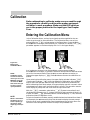
Entering the Calibration Menu
In the Calibration Menu, various input signals must be supplied for the controller to go through its auto calibration. The Calibration Menu can only be
entered from the [`LOC] Lock parameter in the Setup Menu. Press the ¿Uparrow/¯Down-arrow keys simultaneously for 3 seconds (± 1 second). The [`CAL]
parameter appears in the lower display with "no" in the upper display.
93
93
Figure A.3 Entering the
Calibration Menu.
NOTE:
While in the Calibration Menu, the controller output(s) go
off and the alarm
output (if present) is
on.
Watlow Series 93
Upon entering the calibration menu, the upper display window indicates [`CAL].
It continues to indicate [`CAL] (with the exception of calibration of the 4-20mA
output) while the operator walks through the entire calibration parameter list.
While calibrating the 4-20mA output, the upper display contains a numeric value
to be slewed up or down until the output value is correct. The controller uses the
lower display to prompt the user as to what the input should be.
With the [`dFL] parameter, select either [``SI] (System International) and
the displayed parameters are °C, integral, derivative and proportional band in %
of span. Or select [``US] parameters which include displaying °F, rate, reset and
proportional band in degrees or units.
Once the information has been properly established and maintained for at least 5
to 10 seconds, the ‰Advance key may then be used to display the next prompt.
After the final input is established, press the ‰Advance key twice to return the
controller to the configuration menu at the top of the parameter list.
Appendix ■ A.3
Appendix
NOTE:
Calibration values
will not be retained
unless you are in the
MANUAL mode. Do
not enter the MANUAL mode until you
are at the correct
input parameters.
Any inadvertent change in the displayed data, when pressing the ¿Uparrow/¯Down-arrow keys, is ignored. Calibration values won't be retained unless
you are in the manual mode. Press the ¿Up-arrow or ¯Down-arrow key to
change the upper display to [`YES] Press ‰Advance to enter the calibration sequence.
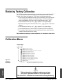
Restoring Factory Calibration
The [`rSt] parameter restores the factory calibration values to the Series 93. If
you calibrate your controller incorrectly, you have the option to default to the
original values. Once you leave the [`CAL] menu, the values are entered.
1. Press the ¿Up-arrow/¯Down-arrow keys simultaneously for three seconds.
The LOC parameter appears in the lower display. Continue holding the
¿Up-arrow/¯Down-arrow keys until the lower display reads [`CAL].
2. Press the ¿Up-arrow key until [`YES] appears in the upper display.
3. ‰Advance through the Calibration Menu until [`rSt] appears in the lower
display.
4. Press the ¿Up-arrow key until [`YES] appears in the upper display.
5. Press the ‰Advance key and the Series 93 advances to test the displays.
6. To conclude, wait 60 seconds or press the ‰Advance key to reach the next
prompt or to exit from the CAL menu.
This procedure is used only to restore calibration, it is not meant to clear values.
Calibration Menu
Calibration Menu
[``NO] [`YES]
[`CAL] [`CAL]
‰
Figure A.4 Calibration
Parameters.
‰
‰
[`)00] Input 0.00mV for low input.
[`5)0] Input 50.00mV for high input.
[``tC] Connect a Type "J" ambient compensator with inputs shorted.
[`440] Set the low resistance to 44.01Ω.
[`255] Set the high resitance to 255.42Ω.
[`)00] Set the voltage source to 0.000 volts.
[`%00] Set the voltage source to 5.000 volts.
[`$00] Set the current source to 4.00mA
[`2)0] Set the current source to 20.00mA
[`4A0] Enter 4-20mA output calibration value for 4mA
[`2A0] Enter 4-20mA output calibration value for 20mA
[`rSt] Restores factory calibration values.
[`dSP] Test display.
[`dFL] Select SI (integral, derivative, proportional band in % of span, °C)
or US (rate, reset, proportional band in degrees or units, °F)
ç
Appendix
Before attempting to calibrate, make sure you have
the proper equipment called for in each procedure.
The Series 93 is calibrated and tested before leaving the factory.
A.4 ■ Appendix
Watlow Series 93
Thermocouple Field Calibration Procedure
Equipment Required
NOTE:
Before calibrating an
installed controller,
make sure all data
and parameters are
documented. See
the Setup and
Operation Tables in
Chapter Four.
• Type "J" Reference Compensator with reference junction at 0°C/32°F, or Type "J"
Thermocouple Calibrator set at 0°C/32°F.
• Precision millivolt source, 0-50mV min. range, 0.01mV resolution
Setup And Calibration
1. Connect the ac line voltage L1 and L2 to the proper terminals.
2. Connect the millivolt source to Terminal 5 Negative and Terminal 3 Positive on the
Series 93 terminal strip. Use regular 20 - 24 gauge wire. Make sure the DIP switch is
set for thermocouple input. See Chapter Four.
3. Apply power to the controller and allow it to warm up for 15 minutes. After warm-up
put the controller in the Calibration Menu. See Figure A.3. Select [`YES].
4. Press the ˆInfinity key twice to enter the manual mode. The controller is calibrating
when % indicator light is on. Make sure the controller is in manual mode only when
you are in the correct parameters.
5. At the 0.00 prompt, enter 0.00mV from the millivolt source to the controller. Allow at
least 10 seconds to stabilize. Press the ‰Advance key.
6. At the 50.0 prompt, enter 50.00mV from the millivolt source to the Series 93. Allow at
least 10 seconds to stabilize. Press the ‰Advance key.
7. At the [``tC] prompt, disconnect the millivolt source, and connect the reference compensator or thermocouple calibrator to Terminal 5 Negative, and Terminal 3 Positive
on the Series 93 terminal strip. If using a compensator, turn on and short the input
wires. If using the "J" calibrator, set it to simulate 0°C/32°F. Allow 10 seconds for the
controller to stabilize. The controller will leave the [`CAL] mode if one minute passes
between key activations. To conclude the thermocouple calibration, press the ˆInfinity
key twice, then press the ‰Advance key to reach the next prompt or to exit from the
[`CAL] menu.
RTD Field Calibration Procedure
Equipment Required
• 1KΩ precision decade resistance box with 0.01Ω resolution.
NOTE:
When the % indicator light is on, the
controller is automatically calibrating.
Your sequence is
VERY important.
Always move to the
next parameter
before changing the
calibration equipment.
Setup And Calibration
1. Connect the ac line voltage L1 and L2 to the proper terminals.
2. Connect the decade resistance box to Terminal 2, 3 and 5 on the terminal strip. Use
regular 20 - 24 gauge wire of the same length and type. Make sure the DIP switch is
set for RTD input, see Chapter Four.
3. Apply power to the controller and allow it to warm up for 15 minutes. After warm-up
put the controller in the [`CAL] menu. See Figure A.3. Select [`YES]. Press the
‰Advance key until the 440 prompt is displayed.
4. Press the ˆInfinity key twice to enter the manual mode. The controller is calibrating
when the % indicator light is on. Make sure the controller is in manual mode only when
you are in the correct parameters.
Appendix
6. At the 255 prompt, set the decade resistance box to 255.42. Allow at least 10 seconds to
stabilize. Press the ˆInfinity key twice to exit the manual mode. The controller will
leave the [`CAL] mode if one minute passes between key activations. To conclude the
RTD calibration, press the ˆInfinity key twice, then press the ‰Advance key to reach
the next prompt or to exit from the [`CAL] menu.
Watlow Series 93
Appendix ■ A.5
Appendix
5. At the 440 prompt, set the decade resistance box to 44.01. Allow at least 10 seconds to
stabilize. Press the ‰Advance key.
0-5 Volt Input Field Calibration Procedure
Equipment Required
• Precision dc voltage source 0-5 volt minimum range with 0.001 volt resolution.
Setup and Calibration
1. Connect the ac line voltage L1 and L2 to the proper terminals on the Series 93.
NOTE:
Before calibrating an
installed controller,
make sure all data
and parameters are
documented. See
the Setup and
Operation Tables in
Chapter Four .
2. Connect the voltage/current source to Terminal 3 (+) and 5 (-) on the Series 93 terminal
strip. Use regular 20 - 24 gauge wire. Make sure the DIP switch is set for process input,
see Chapter Four.
3. Apply power to the controller and allow it to warm up for 15 minutes. After warm-up
put the controller in the [`CAL] menu. See Figure A.3. Select [`YES]. Press the
‰Advance key until 0.00 is displayed.
4. Press the ˆInfinity key twice to enter the manual mode. The controller is calibrating
when the % indicator light is on. Make sure the controller is in the manual mode only
when you are in the correct parameters.
5. At the 0.00 parameter, set the voltage source to 0.000 volts. Allow at least 10 seconds to
stabilize. Press the ‰Advance key.
6. At the 5.00 parameter, set the voltage source to 5.000VÎ (dc). Allow at least 10 seconds
to stabilize. The controller leaves the [`CAL] mode if 1 minute passes between key activations. Press the ˆInfinity key twice to exit the manual mode. To conclude the 0-5 volt
calibration, press the ˆInfinity key twice, then press the ‰Advance key to reach the
next prompt or to exit from the [`CAL] menu.
4-20mA Input Field Calibration Procedure
Equipment Required:
• Precision current source 0-20mA minimum range with 0.01mA resolution.
Setup and Calibration
NOTE:
When the % indicator light is on, the
controller is automatically calibrating.
Your sequence is
VERY important.
Always move to the
next parameter
before changing the
calibration equipment.
1. Connect the ac line voltage L1 and L2 to the proper terminals on the Series 93.
2. Connect the current source to Terminal 2 (-) and 5 (+) on the Series 93 terminal strip.
Use regular 20 - 24 gauge wire. Make sure the DIP switch is set for process input, see
Chapter Four.
3. Apply power to the controller and allow it to warm up for 15 minutes. After warm-up
put the controller in the [`CAL] menu. See Figure A.3. Select YES. Press the
‰Advance key until 4 is displayed.
4. Press the ˆInfinity key twice to enter the manual mode. The controller is calibrating
when the % indicator light is on. Make sure the controller is in the manual mode only
when you are in the correct parameters.
5. At the 4.00 parameter, set the current source to 4.00mA. Allow at least 10 seconds to
stabilize. Press the ‰Advance key.
Appendix
6. At the 20.0 parameter, set the current source to 20.00mA. Allow at least 10 seconds to
stabilize. The controller leaves the [`CAL] mode if 1 minute passes between key activations. Press the ˆInfinity key twice to exit the manual mode. To conclude, press the
ˆInfinity key twice, then press the ‰Advance key to reach the next prompt or to exit
from the [`CAL] menu.
A.6 ■ Appendix
Watlow Series 93
4-20mA Output Field Calibration Procedure
Equipment Required:
• 300Ω, 1/2 watt 10% resistor.
• 4 - 1/2 digit Digital Multimeter.
NOTE:
Before calibrating an
installed controller,
make sure all data
and parameters are
documented. See
the Setup and
Operation Tables in
Chapter Four.
Setup And Calibration
1. Connect the ac line voltage L1 and L2 to the proper terminals of the Series 93. See
Chapter Two. Set the multimeter to measure current.
2. Connect the multimeter in series with the 300Ω resistor to Terminal 9 Positive and 10
Negative on the Series 93 terminal strip. Use regular 20 - 24 gauge wire.
3. Apply power to the controller and allow it to warm up for 15 minutes. After warm-up
put the controller in the [`CAL] menu. See Figure A.3. Select YES. Press the
‰Advance key until the 4A0 prompt is displayed.
4. Press the ˆInfinity key twice to enter the manual mode. The controller is calibrating
when the % indicator light is on.
NOTE:
When the % indicator light is on, the
controller is automatically calibrating.
Your sequence is
VERY important.
Always move to the
next parameter
before changing the
calibration equipment.
5. At the [`4A0] prompt, the multimeter should read approximately 4mA. Allow at least
10 seconds to stabilize.
6. Use the ¿Up-arrow/¯Down-arrow keys (reverse acting) to adjust the reading on the
multimeter for 3.85mA ± 0.10mA. Press the ‰Advance key.
7. At the [`2A0] prompt, the multimeter should read approximately 20mA. Allow at least
10 seconds to stabilize. The controller will leave the [`CAL] mode if one minute passes
between key activations, except for 4-20mA units.
8. Use the ¿Up/¯Down keys (reverse acting) to adjust the reading on the multimeter for
20.15mA ±0.10mA.
9. To conclude the 4-20mA output calibration, press the ˆInfinity key twice, then press
the ‰Advance key to reach the next prompt or to exit from the [`CAL] menu.
Appendix
Appendix
Watlow Series 93
Appendix ■ A.7
Notes
Appendix
A.8 ■ Appendix
Watlow Series 93
Glossary
compensate for the effective temperature at the cold
junction.
A
compensation, ambient The ability of an instrument to
adjust for changes in the temperature of the environment and correct the readings. Sensors are most accurate when maintained at a constant ambient temperature. When temperature changes, output drifts.
alarm, deviation Warns that a process has exceeded
or fallen below a certain range around the set point.
Alarms can be referenced at a fixed number of degrees,
plus or minus, from set point.
alarm hysteresis A change in the process variable
required to re-energize the alarm output.
alarm silence A feature that disables the alarm relay
output.
anti-reset A control feature that inhibits automatic reset
action outside the proportional band. Also called antireset windup.
control action The response of the control output relative to the error between the process variable and the
set point. For reverse action (usually heating), as the
process decreases below the set point, the output
increases. For direct action (usually cooling), as the
process increases above the set point, the output
increases.
cycle time The time required for a controller to complete one on-off-on cycle. It is usually expressed in seconds.
D-E
anti-reset windup The feature of a PID temperature
controller that prevents the integral (automatic reset) circuit from functioning when the temperature is outside
the proportional band. This standard feature helps stabilize a system. Also called anti-reset.
default parameters The programmed instructions that
are permanently stored in the microprocessor software.
automatic prompts Data entry points where a microprocessor-based controller asks the operator to enter a
control value.
derivative control (D) The last term in the PID control
algorithm. Action that anticipates the rate of change of
the process, and compensates to minimize overshoot
and undershoot. Derivative control is an instantaneous
change of the control output in the same direction as the
proportional error. This is caused by a change in the
process variable (PV) that decreases over the time of
the derivative (TD). The TD is in units of seconds.
B
bumpless transfer A smooth transition from auto
(closed loop) to manual (open loop) operation. The control output(s) does not change during the transfer.
C
calibration offset An adjustment to eliminate the difference between the indicated value and the actual
process value.
derivative The rate of change in a process variable.
Also known as rate. See PID.
Deutsche Industrial Norm (DIN) A set of technical,
scientific and dimensional standards developed in
Germany. Many DIN standards have worldwide recognition.
deviation alarm See alarm, deviation.
DIN See Deutsche Industrial Norm.
CE A manufacturer’s mark that demonstrates compliance with European Union (EU) laws governing products sold in Europe.
direct action An output control action in which an
increase in the process variable causes an increase in
the output. Cooling applications usually use direct
action.
CE-compliant Compliant with the essential requirements of European directives pertaining to safety and/or
electromagnetic compatibility.
display capability In an instrument with digital display,
the entire possible span of a particular parameter or
value.
closed loop A control system that uses a sensor to
measure a process variable and makes decisions based
on that input.
droop In proportional controllers, the difference
between set point and actual value after the system stabilizes.
cold junction See junction, cold.
duty cycle The percentage of a cycle time in which the
output is on.
cold junction compensation Electronic means to
Watlow Series 93
Appendix ■ A.9
Appendix
alarm A signal that indicates that the process has
exceeded or fallen below the set or limit point. For
example, an alarm may indicate that a process is too hot
or too cold.
F-G
Form A A single-pole, single-throw relay that uses only
the normally open (NO) and common contacts. These
contacts close when the relay coil is energized. They
open when power is removed from the coil.
Form C A single-pole, double-throw relay that uses the
normally open (NO), normally closed (NC) and common
contacts.
H
hysteresis A change in the process variable required to
re-energize the control or alarm output. Sometimes
called switching differential.
I
integral Control action that automatically eliminates offset, or droop, between set point and actual process temperature. See reset, automatic.
integral control (I) A form of temperature control. The I
of PID. See integral.
isolation Electrical separation of sensor from high voltage circuitry. Allows use of grounded or ungrounded
sensing element.
J-K
JIS See Joint Industrial Standards.
Joint Industrial Standards (JIS) A Japanese agency
that establishes and maintains standards for equipment
and components. Also known as JISC (Japanese
Industrial Standards Committee), its function is similar to
Germany’s Deutsche Industrial Norm (DIN).
junction The point where two dissimilar metal conductors join to form a thermocouple.
junction, cold Connection point between thermocouple
metals and the electronic instrument. See reference
junction.
junction, reference The junction in a thermocouple circuit held at a stable, known temperature (cold junction).
Standard reference temperature is 32°F (0°C).
L
Appendix
limit or limit control A highly reliable, discrete safety
device (redundant to the primary controller) that monitors
and limits the temperature of the process, or a point in
the process. When temperature exceeds or falls below
the limit set point, the limit controller interrupts power
A.10 ■ Appendix
through the load circuit. A limit control can protect equipment and people when it is correctly installed with its
own power supply, power lines, switch and sensor.
M
manual mode A selectable mode that has no automatic
control aspects. The operator sets output levels.
N
NEMA 4X A NEMA specification for determining resistance to moisture infiltration and corrosion resistance.
This rating certifies the controller as washable and corrosion resistant.
O
offset (process) The difference in temperature
between the set point and the actual process temperature. Offset is the error in the process variable that is typical of proportional-only control. See also droop.
on/off A method of control that turns the output full on
until set point is reached, and then off until the process
error exceeds the hysteresis.
open loop A control system with no sensory feedback.
output Control signal action in response to the difference between set point and process variable.
overshoot The amount by which a process variable
exceeds the set point before it stabilizes.
P-Q
P control Proportioning control.
parallel circuit A circuit configuration in which the same
voltage is applied to all components, with current divided
among the components according to their respective
resistances or impedances.
parameter A variable that is given a constant value for
a specific application or process.
PD control Proportioning control with derivative (rate)
action.
percent power control Open loop control with output
power set at a particular level.
percent power limit Restriction of output power to a
predetermined level.
PI control Proportioning control with integral (automatic
reset) action.
Watlow Series 93
PID Proportional, integral, derivative. A control mode
with three functions: proportional action dampens the
system response, integral corrects for droop, and derivative prevents overshoot and undershoot.
increase in the process variable causes a decrease in
the output. Heating applications usually use reverse
action.
RTD See resistance temperature detector.
process variable The parameter that is controlled or
measured. Typical examples are temperature, relative
humidity, pressure, flow, fluid level, events, etc. The high
process variable is the highest value of the process
range, expressed in engineering units. The low process
variable is the lowest value of the process range.
S
programmed display data Displayed information that
gives the operator the intended process information,
such as intended set point, intended alarm limit, etc.,
corresponding to temperature.
switching sensitivity In on/off control, the temperature
change necessary to change the output from full on to
full off. See hysteresis.
prompt A symbol or message displayed by the controller that requests input from the user.
T-Y
proportional band (PB) A range in which the proportioning function of the control is active. Expressed in
units, degrees or percent of span. See PID.
proportional control A control using only the P (proportional) value of PID control.
R
rate Anticipatory action that is based on the rate of temperature change, and compensates to minimize overshoot and undershoot. See derivative.
reference junction See junction.
reset Control action that automatically eliminates offset,
or droop, between set point and actual process temperature. Also see integral.
reset, automatic The integral function of a PI or PID
temperature controller that adjusts the process temperature to the set point after the system stabilizes. The
inverse of integral.
reset windup inhibit See anti-reset.
resistance temperature detector (RTD) A sensor that
uses the resistance temperature characteristic to measure temperature. There are two basic types of RTDs:
the wire RTD, which is usually made of platinum, and
the thermistor, which is made of a semiconductor material. The wire RTD is a positive temperature coefficient
sensor only, while the thermistor can have either a negative or positive temperature coefficient.
thermal system A regulated environment that consists
of a heat source, heat transfer medium or load, sensing
device and a control instrument.
thermocouple (t/c) A temperature sensing device
made by joining two dissimilar metals. This junction produces an electrical voltage in proportion to the difference
in temperature between the hot junction (sensing junction) and the leadwire connection to the instrument (cold
junction).
thermocouple break protection The ability of a control
to detect a break in the thermocouple circuit and take a
predetermined action.
three-mode control Proportioning control with integral
(reset) and derivative (rate). Also see PID.
time proportioning control A method of controlling
power by varying the on/off duty cycle of an output. This
variance is proportional to the difference between the set
point and the actual process temperature.
triac A solid state device that switches alternating current.
Z
zero cross Action that provides output switching only at
or near the zero-voltage crossing points of the ac sine
wave. See burst fire.
zero switching See zero cross.
Appendix
proportional Output effort proportional to the error from
set point. For example, if the proportional band is 20°
and the process is 10° below set point, the heat proportioned effort is 50 percent. The lower the PB value, the
higher the gain.
set point The desired value programmed into a controller. For example, the temperature at which a system
is to be maintained.
reverse action An output control action in which an
Watlow Series 93
Appendix ■ A.11
• Solid-state relay3, Form A, 0.5A @ 24V~ (ac) min., 264V~ (ac)
max., opto-isolated burst fire switched, without contact suppression. Off-state output impedance is 31MΩ.
• Alarm output can be latching or non-latching, and process or deviation with separate high and low values. Alarm silencing (inhibit)
on power up (for deviation alarms only).
Output Configurations
Specifications (1639)
• Output 1
Control Mode
User-selectable as: on-off: P, PI, PD, PID, heat or cool action
• Microprocessor-based, user-selectable control modes
• Adjustable switching differential: 1 to 55°C (1 to 99°F)
• Single input, dual output
• Proportional band: 0 (off) or 0 to 555°C (1 to 999°F) or 0.0 to
• 2.5Hz Input Sampling Rate
999.9 units
• 1Hz Display Update Rate
Integral: 0 (off) or 0.1 to 99.9 minutes per repeat
• Ramp to set point: 0 to 9999 degrees or units per hour
Reset: 0 (off) or 0.01 to 9.99 repeats per minute
• Heat and cool autotune
Rate/derivative: 0 (off) or 0.01 to 9.99 minutes
Operator Interface
Cycle time: 0.1 to 999.9 seconds
• Sealed membrane front panel
• Output 2
• Dual, four-digit red or green displays
User selectable as: Control with action opposite that of Output 1
• ‰Advance, ¿Up-arrow, ¯Down-arrow, and ˆInfinity keys
(heating or cooling)
• User-selectable screen display
• Process or deviation alarm with flashing alarm message
Accuracy
• Process or deviation alarm without alarm message
• Calibration accuracy and sensor conformity: ±0.1% of span, ±1°C • Alarm with separate high and low set points
@ 25°C ± 3°C (77°F ± 5°F) ambient and rated line voltage
• Hysteresis: 1 to 9999° or units switching differential
• Accuracy span: 540°C (1000°F) minimum
Line Voltage/Power
• Temperature stability: ±0.2°C/°C (±0.2°F/°F) rise in ambient maxi- • 100-240V~ (ac), -15%, +10%4; (85-264V~ [ac]) 50/60Hz, ±5%
mum
• 12-24Vı (ac/dc), +10%, -15%; (10-26Vı [ac/dc]) 50/60Hz, ±5%
Sensors/Inputs
• Fused internally(factory replaceable only) Slo-Blo® type (time-lag):
• Thermocouple, grounded or ungrounded sensors
1A, 250V for high voltage versions
• RTD 2- or 3-wire, platinum, 100Ω @ 0°C calibration to DIN curve
2A, 250V for low voltage versions
(0.00385Ω/Ω/°C) or JIS curve (0.003916Ω/Ω/°C); user-selectable • Maximum power consumption: 12VA (100 to 240V~), 7VA (12 to
• Process, 4-20mA @ 5Ω, or 0-5VÎ (dc) @ 10kΩ input impedance
24Vı)
• Sensor break protection de-energizes control output to protect
• Data retention upon power failure via non-volatile memory
system or selectable bumpless transfer to manual operation
Operating Environment4
• °C or °F or process units display, user-selectable
• 0 to 65°C (32 to 149°F).
Input Range
• 0 to 90% RH, non-condensing
Specified temperature ranges represent the controller’s operation- Storage Temperature
al span.
• -40° to 85°C (-40° to 185°F)
• Thermocouple
Terminals
Type J
0
to 750°C
• #6 compression universal head screw terminals, accepts 20-14
(32
to 1382°F)
gauge wire
Type K
-200
to 1250°C
Controller Weight
(-328 to 2282°F)
• 0.2 kg (0.4 lb)
Type N
0
to 1250°C
Shipping Weight
(32
to 2282°F)
• 0.34 kg (0.75 lb)
Type S
0
to 1450°C
Dimensions
(32
to 2642°F)
• Compact 1⁄16 DIN size and IP652 (NEMA 4X), front panel make
Type T
-200
to 350°C
the Series 93 easy to apply and maintain in a wide variety of
(-328 to 662°F)
applications. The unique mounting bezel, gasket and collar make
• RTD Resolution (DIN or JIS)
installation a snap.
1°
-200
to 700°C
Overall Height: 55 mm
(2.1 inches)
(-328 to 1292°F)
Width:
55 mm
(2.1 inches)
0.1°
-128.8 to 537.7°C
Depth:
120 mm
(4.7 inches)
(-199.9 to 999.9°F)
Bezel Height:
55 mm
(2.1 inches)
• Process
Width:
55 mm
(2.1 inches)
4-20mA @ 5Ω, or -999 to 9999 units
Depth:
15 mm
(0.6 inches)
0-5V (dc) @ 10kΩ, or -999 to 9999 units
Chassis Height: 45 mm
(1.8 inches)
Output 1 (Heating or Cooling)
Width:
45 mm
(1.8 inches)
1
• Electromechanical relay , Form C, 5A @ 120/240V~ (ac) maxiDepth:
105 mm
(4.1 inches)
mum, without contact suppression, rated resistive load, 5A @
Agency Approvals
30VÎ (dc)3. Minimum contact current, 100mA @ 5VÎ (dc).
• UL508®, c-UL, CE, IP65 (NEMA 4X), File #E102269
• Switched dc signal provides a non-isolated minimum turn on volt- • CE:
age of 3VÎ (dc) into a minimum 500Ω load; maximum on voltage
89/336/EEC (EN 50082-2, EN 50081-2)
not greater than 12VÎ (dc) into an infinite load.
73/23/EEC (EN61010-1)
• 4-20mA reverse or direct acting, non-isolated 0 to 800Ω load.
3
• Solid-state relay , Form A, 0.5A @ 24V~ (ac) min., 264V~ (ac)
1 Electromechanical relays warranted for 100,000 closures only.
max., opto-isolated burst fire switched, without contact suppresSolid-state switching devices recommended for applications
sion. Off-state output impedance is 31MΩ.
requiring fast cycle times or extended service life.
Output 2 (Heat, Cool or Alarm)
2 To effect IP65 (NEMA 4X) rating requires a minimum mounting
1
• Electromechanical relay , Form C, 5A @ 120/240V~ (ac) maxipanel thickness of 1.5 mm (0.06 inch) and surface finish not
mum, without contact suppression, rated resistive load, 5A @
rougher than 0.000812 mm (0.000032 inch).
30VÎ (dc)3. Minimum contact current, 100mA @ 5VÎ (dc).
3 Switching inductive loads (relay coils, etc.) requires using an RC
• Switched dc signal provides a non-isolated minimum turn on voltsuppressor.
age of 3VÎ (dc) into a minimum 500Ω load; maximum on voltage 4 Operating environment is 0 to 60°C for live voltage exceeding 240V.
not greater than 12VÎ (dc) into an infinite load.
Specifications
Appendix
A.12 ■ Appendix
Watlow Series 93
Series 93 Model Number Information
Ordering Information
(1068)
93 _ _ - 1 _ _ _ - 0 0_ _
Part Number
Microprocessor-based
1/16 DIN, Single Input, Dual Output,
Two-, Four-Digit Displays
IP65/NEMA 4X2 Option
A = Without IP65/NEMA 4X Rating
B = With IP65/NEMA 4X Rating
CE Option
A = Without CE
B = With CE
Output 1
C = Switched dc output, non-isolated
D = Electromechanical relay, Form C, 5A,
without contact suppression1, 3
F = Process, 4-20mA (dc), non-isolated
K = Solid-state relay, Form A, 0.5A, without
contact suppression3
Output 2
A = None
C = Switched dc output, non-isolated
D = Electromechanical relay, Form C, 5A,
without contact suppression1, 3
K = Solid-state relay, Form A, 0.5A,
without contact suppression3
Line Voltage/Power
0 = 100 to 240V~ (ac) nominal (high voltage)
1 = 12 to 24Vı (ac/dc) (low voltage)
Display
1
Electromechanical relays warranted for 100,000 closures only. Solid-state switching devices recommended for applications requiring fast cycle times or extended service life.
2
To effect IP65/NEMA 4X rating requires a minimum mounting panel thickness of 1.5 mm (0.06 inch)
and surface finish not rougher than 812µ mm (0.32µ inch).
3
Switching inductive loads (relay coils, etc.) requires using an RC suppressor.
Watlow Series 93
Appendix
Upper/Lower
RR = Red/Red
RG = Red/Green
GR = Green/Red
GG = Green/Green
Appendix ■ A.13
Index
A
‰Advance key 3.1
Alarm High 4.7
Alarm Low 4.7
alarm silencing 5.5
alarms 5.4
automatic operation 5.3
autotuning 5.1
Autotune 4.7
J-K
Keys 3.1
B-C
calibration A.3
Calibration Menu A.4
Calibration Offset 4.7
Celsius-Fahrenheit 4.3
clearing an alarm 5.4
Cycle Time 4.6
M
manual operation 5.3
manual tuning 5.2
mechanical relay, 5 Amp
Output 1 Wiring 2.6
Output 2 Wiring 2.8
Model Number A.13
mounting collar 2.2
mounting case 2.2
D
default parameters
Operation 4.6-4.7
Setup 4.3-4.5
Derivative 4.6
Deviation alarm 5.4
dimensions
faceplate 2.1
panel cutout 2.1
side view 2.1
DIP Switches 4.1
Display 3.1, 4.5
¯Down-arrow key 3.1
E
entering the Setup Menu 4.2
error codes 5.5-5.6
F
field calibration A.5-A.7
G
general description 1.1
Glossary A.9
H
high voltage wiring 2.3
Hysteresis 4.4
Appendix
I
indicator lights 3.1
ˆInfinity key 3.1
Input
wiring 2.4
DIP Switch 4.1
ranges 4.5
RTD 4.4
thermocouple 2.4
type 4.3
Integral 4.6
A.14 ■ Appendix
L
ladder wiring diagram 2.9
Latching 4.4, 5.4
Lock Parameter 4.3
low voltage wiring 2.3
Lower Display 3.1
N
Noise
eliminating A.2
sources A.1
decreasing sensitivity A.1
returns back cover
RTD Calibration A.5
RTD Sensor Wiring 2.4
S
sensor installation 2.4
Set Point 4.6
Setup Menu 4.1, 4.2
Setup Parameters 4.3
Silencing 4.4
Specifications A.12
T
thermocouple calibration A.5
thermocouple sensor wiring 2.4
tuning 5.1-5.3
U-Z
¿Up-arrow key 3.1
Upper Display 3.1
warranty back cover
wiring 2.3
wiring example 2.9
O
Operation Menu 4.6-4.7
Operation Parameters 4.6
Output 1 4.4
Output 2 4.4
Output Wiring
5A Mechanical Relay 2.6, 2.8
4-20mA 2.7
switched dc 2.7, 2.8
solid-state relay 2.6, 2.8
overview of the Series 93 1.1
P
%Percent Power Indicator Light 3.1
Power Limiting 4.5
power wiring 2.3
process alarm 5.4
process input 2.5
Proportional Band 4.6
Q
Quick Reference Sheet A.17-A.18
R
Ramping 4.4
Range High 4.4
Range Low 4.3
Rate 4.6
removing controller 2.2
Reset 4.6
restoring calibration A.4
Watlow Series 93
Declaration of Conformity
97
WATLOW CONTROLS
1241 Bundy Boulevard
Winona, Minnesota 55987 USA
Declares that the following product:
English
Designation:
Series 93
Model Number(s):
93(A or B) (A or B) - 1 (C D F or K) (A C D or K) (0 or
1) - (Any four letters or numbers)
Classification:
Control, Installation Category II, Polution Degree II
Rated Voltage:
100 to 240V or 24
Rated Frequency:
50/60 Hz
Rated Power Consumption: 6VA maximum
Meets the essential requirements of the following European Union Directive(s) using
the relevant section(s) of the normalized standards and related documents shown:
89/336/EEC Electromagnetic Compatibility Directive
EN 50082-2:
1995 EMC Generic immunity standard, Part 2: Industrial
environment
1995 Limits for harmonic current
1995 Limitations of voltage fluctuatuions and flicker
1995 Electrostatic discharge
1995 Electrical fast transients
1996 Radiated immunity
1996 Conducted immunity
1995 Cellular phone
1994 EMC Generic emission standard, Part 2: Industrial
environment
1991 Limits and methods of measurement of radio
disturbance characteristics of industrial, scientific and medical
radio-frequency equipment (Group 1, Class A)
1995 Limits for harmonic current emissions
1995 Limitations of voltage fluctuations and flicker
EN 61000-3-2:
EN 61000-3-3:
EN 61000-4-2:
EN 61000-4-4:
EN 61000-4-3:
EN 61000-4-6:
ENV 50204:
EN 50081-2:
EN 55011:
EN 61000-3-2:
EN 61000-3-3:
73/23/EEC Low-Voltage Directive
EN 61010-1:
1993 Safety requirements for electrical equipment for
measurement, control, and laboratory use,
Part 1: General requirements
Déclare que le produit suivant :
Français
Désignation :
Série 93
Numéro(s) de modèle(s) :
93(A ou B)(A ou B)-1(C, D, F ou K) (A, C, D ou K) (0
ou 1) - (quatre lettres ou chiffres quelconques)
Classification :
Commande, installation catégorie II, degré de
pollution II
Tension nominale :
100 à 240 V ou 24
Fréquence nominale :
50/60 Hz
Consommation
d’alimentation nominale :
6 VA maximum
Conforme aux exigences de la (ou des) directive(s) suivante(s) de l’Union
Européenne figurant aux sections correspondantes des normes et documents
associés ci-dessous :
89/336/EEC Directive de compatibilité électromagnétique
EN 50082-2 :
EN 61000-3-2 :
EN 61000-3-3 :
EN 61000-4-2 :
EN 61000-4-4 :
EN 61000-4-3:
EN 61000-4-6:
ENV 50204 :
EN 50081-2 :
EN 55011 :
EN 61000-3-2 :
EN 61000-3-3 :
1995 Norme générique d’insensibilité électromagnétique,
Partie 2 : Environnement industriel
1995 Limites de courant harmonique
1995 Limites de fluctuation et de vacillement de la tension
1995 Décharge électrostatique
1995 Courants électriques transitoires rapides
1996 Insensibilité à l’énergie rayonnée
1996 Insensibilité à l’énergie par conduction
1995 Téléphone cellulaire
1994 Norme générique sur les émissions électromagnétiques,
Partie 2 : Environnement industriel
1991 Limites et méthodes de mesure des caractéristiques
d’interférences du matériel radiofréquence industriel,
scientifique et médical (Groupe 1, Classe A)
1995 Limites d’émission d’harmoniques
1995 Limitations d’écarts de tension et de papillotement
73/23/EEC Directive liée aux basses tensions
EN 61010-1 :
1993 Exigences de sécurité pour le matériel électrique de
mesure, de commande et de laboratoire,
Partie 1 : Exigences générales
Erklärt, daß das folgende Produkt:
Deutsch
Beschreibung:
Serie 93
Modellnummer(n):
9 3 (A oder B) (A oder B) - 1 (C D F oder K) (A C D oder
K) (0 oder 1) - (4 beliebige Buchstaben oder Ziffern)
Klassifikation:
Regelsystem, Installationskategorie II, Emissionsgrad II
Nennspannung:
100 bis 240 V oder 24 bis 28 V
Nennfrequenz:
50/60 Hz
Nominaler
Stromverbrauch:
Max. 6 VA
Erfüllt die wichtigsten Normen der folgenden Anweisung(en) der Europäischen
Union unter Verwendung des wichtigsten Abschnitts bzw. der wichtigsten Abschnitte
der normalisierten Spezifikationen und der untenstehenden einschlägigen
Dokumente:
89/336/EEC Elektromagnetische Übereinstimmungsanweisung
EN 50082-2:
EN 61000-3-2:
EN 61000-3-3:
EN 61000-4-2:
EN 61000-4-4:
EN 61000-4-3:
EN 61000-4-6:
ENV 50204:
EN 50081-2:
EN 55011:
EN 61000-3-2:
EN 61000-3-3:
1995 EMC-Rahmennorm für Störsicherheit, Teil 2: Industrielle
Umwelt
1995 Grenzen der Oberwellenstromemission
1995 Grenzen der Spannungsschwankungen und Flimmern
1995 Elektrostatische Entladung
1995 Elektrische schnelle Stöße
1996 Strahlungsimmunität
1996 Störimmunität
1995 Mobiltelefon
1994 EMC-Rahmennorm für Emissionen, Teil 2: Industrielle
Umwelt
1991 Beschränkungen und Methoden der Messung von
Funkstörungsmerkmalen industrieller, wissenschaftlicher und
medizinischer Hochfrequenzgeräte (Gruppe 1, Klasse A)
1995 Grenzen der Oberwellenstromemissionen
1995 Grenzen der Spannungsschwankungen und Flimmern
73/23/EEC Niederspannungsrichtlinie zu entsprechen
EN 61010-1:
1993 Sicherheitsrichtlinien für Elektrogeräte zur Messung, zur
Steuerung und im Labor,
Teil 1: Allgemeine Richtlinien
Declara que el producto siguiente:
Español
Designación:
Serie 93
Números de modelo:
9 3 (A o B) (A o B) - 1 (C D F o K) (A C D o K) (0 ó 1) (Cualquier combinación de cuatro números y letras)
Clasificación:
Control, categoría de instalación II, grado de
contaminación ambiental II
Tensión nominal:
100 a 240 V o 24
Frecuencia nominal:
50/60 Hz
Consumo nominal
de energía:
6 VA máximo
Cumple con los requisitos esenciales de las siguientes directivas de la Unión
Europea, usando las secciones pertinentes de las reglas normalizadas y los
documentos relacionados que se muestran:
89/336/EEC Directiva de Compatibilidad Electromagnética
EN 50082-2:
EN 61000-3-2
EN 61000-3-3
EN 61000-4-2:
EN 61000-4-4:
EN 61000-4-3:
EN 61000-4-6:
ENV 50204:
EN 50081-2:
EN 55011:
EN 61000-3-2:
EN 61000-3-3:
1995 Norma de inmunidad genérica del EMC, Parte 2:
Ambiente industrial
1995 Límites para corriente armónica
1995 Limitaciones de oscilaciones y fluctuaciones de voltaje
1995 Descarga electrostática
1995 Perturbaciones transitorias eléctricas rápidas
1996 Inmunidad radiada
1996 Inmunidad conducida
1995 Teléfono portátil
1994 Norma de emisión genérica del EMC, Parte 2: Ambiente
industrial
1991 Límites y métodos para medición de características de
perturbaciones de radio correspondientes a equipos de
radiofrecuencia industriales, científicos y médicos (Grupo 1,
Clase A)
1995 Límites para emisiones de corriente armónica
1995 Limitaciones de fluctuaciones del voltaje
73/23/EEC Directiva de Baja Tensión
EN 61010-1:
1993 Requerimientos de seguridad para equipos eléctricos de
medición, control y uso en laboratorios,
Parte 1: Requerimientos generales
Erwin D. Lowell
Name of Authorized Representative
General Manager
Title of Authorized Representative
Winona, Minnesota, USA
Place of Issue
November, 1997
Date of Issue
________________________________________
Signature of Authorized Representative
(1505)
Watlow Series 93
Appendix ■ A.15
Appendix
Series 93
Notes
Appendix
A.16 ■ Appendix
Watlow Series 93
Series 93 Quick Reference
Keys and Displays
Alarms
A process alarm sets an absolute temperature. When the process
exceeds that absolute temperature limit, an alarm occurs. The
process alarm set points may be independently set high and low.
Under the Setup Menu, select the type of alarm output with the
[`Ot2] parameter. [`PrA] sets a process alarm with alarm message displayed. [``Pr] sets a process alarm with no alarm message displayed.
A deviation alarm alerts the operator when the process strays
too far from the set point. The operator can enter independent high
and low alarm settings. The reference for the deviation alarm is
the set point. Any change in set point causes a corresponding shift
in the deviation alarm. [`dEA] sets a deviation alarm with alarm
message displayed. [``dE] sets a deviation alarm with no alarm
message displayed.
Example: If your set point is 100°F, and a deviation alarm is set to
+7°F as the high limit, and -5°F as the low limit, the high alarm
trips at 107°F, and the low alarm at 95°F. If you change the set
point to 130°F, the alarms follow the set point and trip at 137°F
and 125°F.
To clear an alarm:
• First correct the alarm condition, then…
• If the alarm is latching:
Clear it manually; press the ˆInfinity key once as soon as the
process temperature is inside the [`HSA] parameter alarm
limit.
• If the alarm is non-latching:
The alarm clears itself automatically as soon as the process
temperature is inside the [`HSA] parameter.
Press once
to clear a
latched and
corrected
alarm.
Flashing [`LO`] or [`HI`] in the lower display indicates an alarm
when [`Ot2] is set to [`PrA] or [`dEA]. The lower display
alternately shows information from the current parameter and
the [`LO`] or [`HI`] alarm message at one-second intervals.
The alarm output is de-energized and the Output 2 indicator
light is lit.
Alarm Silencing is available with the deviation alarm and has
two uses:
When [`SIL] is set to "on," the operator must manually disable
the alarm by pressing the ˆInfinity key once on initial power up
(in either the latching or non-latching mode). Alarm silencing disables the alarm output relay. However, the Output 2 indicator light
(also the lower display when [`Ot2] is set to [`dEA]) shows an
alarm condition until the process value is within the “safe” region
of the deviation alarm band. Once the process value crosses into
the “safe” region, both a latching or a non-latching alarm is ready.
Any future deviation outside this safe band triggers an alarm.
Latching: Both process and deviation alarms can be latching or
non-latching. When the alarm condition is removed a non-latching alarm automatically clears the alarm output. You must
manually clear a latching alarm before it will disappear.
Four dashes [----] in the upper display
indicate a Series 93 error. The error code is
visible in the lower display.
[`Er2] - Sensor underrange error
(applies only to RTD units)
The sensor input generated a value lower
than the allowable signal range, or the analog-to-digital circuitry malfunctioned. Enter
a valid input. Make sure the [``In] parameter (Setup Menu) and
the DIP switch settings both match your sensor.
[`Er4] - Configuration error
The controller’s microprocessor is faulty; call the factory.
[`Er5] - Nonvolatile checksum error
The nonvolatile memory checksum discovered a checksum error.
Unless a momentary power interruption occurred while the controller was storing data, the nonvolatile memory is faulty. Call the
factory.
Watlow Series 93
[`Er6] - Analog-to-digital underflow error
The analog-to-digital circuit is underrange. An open or reversed
polarity sensor is the most likely cause. Check the sensor; if the
connection is good and functions properly, call the factory. The analog-to-digital underrange voltage is too low to convert an analog-todigital signal. Make sure the In parameter matches your sensor
and the DIP switches are set accordingly.
[`Er7] - Analog-to-digital overflow error
The analog-to-digital circuit is overrange. An open or reversed
polarity sensor is the most likely cause. Check the sensor; if the
connection is good, and the sensor functions properly, call the factory. The analog-to-digital overrange voltage is too high to convert an
analog-to-digital signal. Make sure the [``In] parameter (Setup
Menu) matches your sensor and the DIP switches are set accordingly.
Appendix ■ A.17
Appendix
Errors
Parameter
Setup Menu
Value
Range
Factory Default
Appears If:
0
[```J]
DIP switch-selectable.
[`dEC]
0-4
[```J], [```H], [```t], [```n],
[```S][`rtd], [`r†d], [`0-5], [`420]
0, 0.0, 0.00
[`C_F]
[```C] or [```F]
Dependent on [`dFL]
[``rL]
[``rL] to [``rh]
Input dependent.
[`LOC]
[``In]
93
0
93
[``In] is set to [`0-5]
or [`420]
[``In] is set to [```J],
[```H], [```t], [```n],
[```S], [`rtd], or [`r†d]
Enter the Setup Menu by
pressing the ¿Up-arrow and
¯Down-arrow keys simultaneously for three seconds. The
lower display shows the
[`LOC] Lock parameter, and
the upper display shows its
current level. All keys are
inactive until you release both
keys. You can reach the Lock
parameter from anywhere.
Use the ‰Advance key to
move through the menus and
the ¿Up-arrow and ¯Downarrow keys to select data. You
will not see all parameters in
this menu, depending on the
controller's configuration and
model number.
[``rh]
[``rh] to [``rL]
Input dependent.
[`Ot1]
[`HSC]
[``ht]
2, 0.2, 0.02°C
3, 0.3, 0.03°F
[`Con]
[`LAt]
[``ht] or [``CL]
1 to 55, 0.1 to 5.5, 0.01 to 0.55°C
1 to 99, 0.1 to 9.9, 0.01 to 0.99°F
[`Con] Control
[`PrA] Process Alarm
[``Pr] Process with no alarm message
[`dEA] Deviation alarm
[``dE] Deviation with no alarm message
[``no] None
1 to 5555, 0.1 to 555.5, 0.01 to 55.55°C
1 to 9999, 0.1 to 999.9, 0.01 to 99.99oF
[`LAt] or [`nLA]
2, 0.2, 0.02°C
3, 0.3, 0.03°F
[`nLA]
[`SIL]
[``On] or [`OFF]
[`OFF]
[`rtd]
[`JIS] or [`din]
[`din]
[`rP`]
[`Str] is set to Ramping on power up
[``on] is set to Ramping to set point always
[`OFF] is set to None
[`OFF]
[`rt`]
0 to 9999
100°/hr
[`P`L]
[`dsP]
0 to 100
[`nor] normal
[`SEt] Set Point (lower only)
[`Pro] Process (upper only)
100
[`nor]
[`Ot2]
[`HSA]
[`Ot2] is not set to [`Con]
or [``no]
[`Ot2] is not set to [`Con]
or [``no]
[`Ot2] is set to [`dEA] or
[``dE]
[``In] is set to [`rtd] or
[`r†d]
[``rP] is not set to [`OFF]
Operation Menu
Parameter
[`Pb1]
Note:
Do not enter any values here;
make photocopies instead.
Range
Factory Default
If [`dFL] is set to [``US]:
0 to 555°C/0 to 999°F/0 to 999 Units
0 to 55.5°C/0 to 99.9°F/0 to 99.9 Units
0 is set to on-off control. [`HSC] is set to switch differential
If [`dFL] is set to [``SI]:
0.0 to 999.9% of span
25°F
2.5°F
3%
[`rE1]
0.00 to 9.99 repeats/minute
0.00 = No Reset. Won't appear if [`Pb1] is set to 0
or [`dFL] is set to [``SI].
0.00 repeats/minute
[`It1]
0.0 to 99.9 minutes/rpt. 0.00 = No Integral.
Won't appear if [`Pb1] is set to 0 or [`dFL] is set to [``US].
00.0 minutes/repeat
[`rA1]
0.00 to 9.99 minutes
0.00 = No Rate. Will not appear if [`Pb1] is set to 0
or [`dFL] is set to [``SI].
0.00 minutes
[`dE1]
0.00 to 9.99 minutes. 0.00 = No Derivative.
Won't appear if [`Pb1] is set to 0 or [`dFL] is set to [``US].
0.00 minutes
[`Ct1]
0.1 to 999.9
Won't appear if [`Pb1] = 0, or [`420].
5.0 seconds
[`Pb2]
Same as [`Pb1]. [`Pb2] lower limit = 1, 0.1, 0.01
[`rE2]
Same range as [`rE1].
[`It2]
Same range as [`It1].
[`rA2]
Same range as [`rA1].
[`dE2]
Same range as [`dE1].
[`Ct2]
Same range as [`Ct1].
[`ALO]
Deviation [``dE]
Process [``Pr]
Appendix
[`AHI]
Deviation [``dE]
Process [``Pr]
A.18 ■ Appendix
Value
-999 to 0
[``rL] to [`AHI]
Will not appear if [`Ot2] is set to [``no] or [`Con].
-999
[``rL]
0 to 999
[`ALO] to [``rH]
Will not appear if [`Ot2] is set to [``no] or [`Con].
999
[``rH]
[`CAL]
±100°C/±180°F/±180 Units
0
[`AUt]
0 to 3
0
Watlow Series 93
Watlow Controls
Watlow Controls is a division of Watlow Electric Mfg. Co., St. Louis, Missouri, a
manufacturer of industrial electric heating products, since 1922. Watlow begins
with a full set of specifications and completes an industrial product that is manufactured totally in-house, in the U.S.A. Watlow products include electric heaters,
sensors, controls and switching devices. The Winona operation has been designing solid-state electronic control devices since 1962, and has earned the reputation as an excellent supplier to original equipment manufacturers. These OEMs
depend upon Watlow Controls to provide compatibly engineered controls that
they can incorporate into their products with confidence. Watlow Controls resides
in a 100,000-square-foot marketing, engineering and manufacturing facility in
Winona, Minnesota.
How to Reach Us
TOTAL
CUSTOMER
SATISFACTION
Contact
3 Year Warranty
Your Authorized Watlow Distributor is:
Quality and
Mission
Statement:
Watlow Controls will be
the world’s best
supplier of industrial
temperature control
products, services, and
systems by exceeding
our customers’,
employees’, and
shareholders’
expectations.
• or Phone: 507/454-5300.
• Fax: 507/452-4507.
• For technical support, ask for an Applications Engineer.
• To place an order, ask for Customer Service.
• To discuss a custom option, ask for a Series 93 Product Manager.
Warranty
The Watlow Series 93 is warranted to be free of defects in material and workmanship for 36 months after delivery to the first purchaser for use, providing
that the units have not been misapplied. Since Watlow has no control over their
use, and sometimes misuse, we cannot guarantee against failure. Watlow’s
obligations hereunder, at Watlow’s option, are limited to replacement, repair or
refund of purchase price, and parts which upon examination prove to be defective within the warranty period specified. This warranty does not apply to damage resulting from transportation, alteration, misuse, or abuse.
Returns
• Call or fax Customer Service for a Return Material Authorization (RMA)
number before returning a controller.
• Put the RMA number on the shipping label, and also on a description of the
problem.
• 20% of net price restocking charge applies to all standard units returned to
stock.
Watlow Series 93 User’s Manual
Watlow Controls, 1241 Bundy Blvd., P.O. Box 5580, Winona, MN 55987-5580, Phone: 507/454-5300, Fax: 507/452-4507