1
MICRODIN
User’s Manual
97
TOTAL
CUSTOMER
SATISFACTION
3 Year Warranty
ISO 9001
Registered Company
Winona, Minnesota USA
Communicating Subpanel Temperature Controller
User Levels:
• New User ....................................................... go to page 1.1
• Experienced User .......................................... go to page 2.1
• Expert User .................................................... go to page 2.1
Installers:
• Set-up ............................................................ go to page 2.1
• Wiring & Installation ........................................go to page 3.1
Controls
1241 Bundy Blvd., P.O. Box 5580, Winona, MN USA 55987-5580, Phone: (507) 454-5300, Fax: (507) 452-4507
W0UD-XUMN Rev A
January 1997
Made in the U.S.A.
$10
A
Addendum
MicroDIN User’s Manual & Quick Start Guide
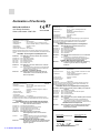
CE Compliance
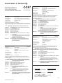
Purpose
To meet Mark CE requirements, this addendum provides supplemental information to the
MicroDIN User’s Manual (W0UD-XUMN Rev A), and the
MicroDIN Quick Start Guide (W0UD-XQRN Rev A).
Power Supply Rating
MicroDIN CE Mark compliance requires an IEC 742 rated power supply. This applies to
the following power supply references:
User’s Manual: p. 3.2, 3.7 (fig. 3.7e), 3.10 (fig. 3.10), 3.11 (fig. 3.11) and A.14
Quick Start Guide: p. 13 (fig. 3.4e), 16, 17 and 22
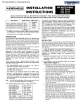
Figure 3.7e—
Power Wiring
1 2 3 4 5 6 7 8 9 10
NOTE: An IEC
742 rated power
supply is
required for CE
compliance.
24V‡ (ac/dc)
- +
-
1 2 3 4 5 6 7 8 9 10
+
-
External
Load
Fuse
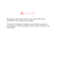
Figures 3.7b
and 13b—
Control Output,
Open Collector
with External
Power Supply
dc
+
dc
C
O
M
External DC Output Fusing
Also, a customer supplied 1A fuse is required for external dc output connection to meet CE
compliance. This applies to the following external dc output references:
User’s Manual: p. 3.7 (fig. 3.7b)
Quick Start Guide: p. 13 (fig. 13b)
- Power
Supply
+ 60V max.
External DC Output Derating
For MicroDIN CE Mark compliance, external load switching (maximum) for an open
collector is derated from 60V @ 1A to 42V @ 1A. This applies to the following output rating
references:
User’s Manual: p. 3.7 (fig. 3.7b) and A.14
Quick Start Guide: p. 13 (fig. 13b) and 22
(1044)
W0UD-XADN Rev A
April 1997
Wa tl ow Mi c roDIN CE Addendum 1
CE Addendum
1A max.
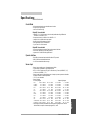
Declaration of Conformity
WATLOW CONTROLS
1241 Bundy Boulevard
Winona, Minnesota 55987 USA
97
Series MicroDIN
Declares that the following product:
English
Designation:
Series MicroDIN
Model Number(s):
UD 1 A -1CES - (Any four numbers or letters)
Classification:
Control, Installation Category II, Polution Degree II
Rated Voltage:
24 to 28V‡ (ac/dc)
Rated Frequency:
50/60 Hz
Rated Power Consumption: 5VA maximum
Meets the essential requirements of the following European Union Directive(s)
using the relevant section(s) of the normalized standards and related documents
shown:
89/336/EEC Electromagnetic Compatibility Directive
EN 50082-2:
1995 EMC Generic immunity standard, Part 2: Industrial
environment
EN 61000-4-2: 1995 Electrostatic discharge
EN 61000-4-4: 1995 Electical fast transients
ENV 50140:
1994 Radiated immunity
ENV 50141:
1994 Conducted immunity
ENV 50204:
1995 Cellular phone
EN 50081-2:
1994 EMC Generic emission standard, Part 2: Industrial
environment
EN 55011:
1991 Limits and methods of measurement of radio disturbance
characteristics of industrial, scientific and medical radiofrequency equipment (Class A)
73/23/EEC Low-Voltage Directive
EN 61010-1:
1993 Safety requirements for electrical equipment for
measurement, control, and laboratory use, Part 1:
General requirements
Déclare que le produit suivant :
Français
Désignation :
Série MicroDIN
Numéro(s) de modèle(s) : UD 1 A - 1CES - (quatre chiffres ou lettres
quelconques)
Classification :
Commande, installation catégorie II, degré de
pollution II
Tension nominale :
24 à 28 V ‡ (c.a./c.c.)
Fréquence nominale :
50/60 Hz
Consommation
d’alimentation nominale :
5 VA maximum
Conforme aux exigences de la (ou des) directive(s) suivante(s) de l’Union
Européenne figurant aux sections correspondantes des normes et documents
associés ci-dessous :
89/336/EEC Directive de compatibilité électromagnétique
1995 Norme générique d’insensibilité électromagnétique,
Partie 2 : Environnement industriel
EN 61000-4-2 : 1995 Décharge électrostatique
EN 61000-4-4 : 1995 Courants électriques transitoires rapides
ENV 50140 :
1994 Insensibilité à l’énergie rayonnée
ENV 50141 :
1994 Insensibilité à l’énergie par conduction
ENV 50204 :
1995 Téléphone cellulaire
EN 50081-2 : 1994 Norme générique sur les émissions
électromagnétiques, Partie 2 : Environnement
industriel
EN 55011 :
1991 Limites et méthodes de mesure des caractéristiques
d’interférences du matériel radiofréquence industriel,
scientifique et médical (Classe A)
Erklärt, daß das folgende Produkt:
Deutsch
Beschreibung:
Serie MicroDIN
Modellnummer(n):
UD 1 A - 1 CES - (4 beliebige Zahlen oder
Buchstaben)
Klassifikation:
Regelsystem, Installationskategorie II,
Emissionsgrad II
Nennspannung:
24 bis 28 V‡ (ac/dc)
Nennfrequenz:
50/60 Hz
Nominaler Stromverbrauch: Max. 5 VA
Erfüllt die wichtigsten Normen der folgenden Anweisung(en) der Europäischen
Union unter Verwendung des wichtigsten Abschnitts bzw. der wichtigsten
Abschnitte der normalisierten Spezifikationen und der untenstehenden
einschlägigen Dokumente:
89/336/EEC EWG Elektromagnetische Verträglichkeit
EN 50082-2:
1995 EMC-Rahmennorm für Störsicherheit, Teil 2:
Industrielle Umwelt
EN 61000-4-2: 1995 Elektrostatische Entladung
EN 61000-4-4: 1995 Elektrische schnelle Stöße
ENV 50140:
1994 Strahlungsimmunität
ENV 50141:
1994 Leitungsimmunität
ENV 50204:
1995 Mobiltelefon
EN 50081-2:
1994 EMC-Rahmennorm für Emissionen, Teil 2: Industrielle
Umwelt
EN 55011:
1991 Beschränkungen und Methoden der Messung von
Funkstörungsmerkmalen industrieller, wissenschaftlicher
und medizinischer Hochfrequenzgeräte (Klasse A)
72/23/EEC EWG Niederspannungsrichtlinie
EN 61010-1:
Declara que el producto siguiente:
Español
Designación:
Serie MicroDIN
Números de modelo:
UD 1 A - 1CES - (Cualquier combinación de cuatro
números y letras)
Clasificación:
Control, categoría de instalación II, grado de
contaminación ambiental II
Tensión nominal:
24 a 28V ‡ (Vca/Vcc)
Frecuencia nominal:
50/60 Hz
Consumo nominal
de energía:
5 VA máximo
Cumple con los requisitos esenciales de las siguientes directivas de la Unión
Europea, usando las secciones pertinentes de las reglas normalizadas y los
documentos relacionados que se muestran:
89/336/EEC Directiva de compatibilidad electromagnética
EN 50082-2: 1995 Norma de inmunidad genérica del EMC, parte 2: Ambiente
industrial
EN 61000-4-2: 1995 Descarga electrostática
EN 61000-4-4: 1995 Perturbaciones transitorias eléctricas rápidas
ENV 50140:
1994 Inmunidad radiada
ENV 50141:
1994 Inmunidad conducida
ENV 50204:
1995 Teléfono portátil
EN 50081-2:
1994 Norma de emisión genérica del EMC, parte 2: Ambiente
industrial
EN 55011:
1991 Límites y métodos de medición de características de
perturbaciones de radio correspondientes a equipos de
radiofrecuencia industriales, científicos y médicos (Clase A)
73/23/EEC Directiva de baja tensión
EN 50082-2 :
73/23/EEC Directive liée aux basses tensions
EN 61010-1 :
1993 Exigences de sécurité pour le matériel électrique
de mesure, de commande et de laboratoire, Partie 1 :
Exigences générales
1993 Sicherheitsrichtlinien für Elektrogeräte zur Messung,
zur Steuerung und im Labor, Teil 1: Allgemeine
Richtlinien
EN 61010-1:
1993 Requerimientos de seguridad para equipos eléctricos
de medición, control y uso en laboratorios, Parte 1:
Requerimientos generales
Erwin D. Lowell
Name of Authorized Representative
Winona, Minnesota, USA
Place of Issue
General Manager
Title of Authorized Representative
February 1, 1997
Date of Issue
________________________________________
Signature of Authorized Representative
(1043)
W0UD-XCEM-0000 Rev A01
Meet the MicroDIN Team
TOTAL
CUSTOMER
SATISFACTION
3 Year Warranty
We stand behind our product and are committed to your total satisfaction.
Pictured below are some of the people at Watlow who have worked hard to
bring you one of the finest industrial temperature controllers available today.
Included in the photo are members of the development team, production team,
and representatives from our core manufacturing and customer service areas.
Front Row: Rob Hermann, board assembly; Gene Lauer, product manager; Keith Ness, engineering team leader;
Steve Lubahn, group leader; Doug Wolfe, technician; Mark Hoven, engineer. 2nd Row, Sitting behind Front Row:
Sally Kotschevar, purchasing; Lisa Voelker, technician; Carolyn Konkel, wave inspection; Mollee Smith, PACE line;
John Pham, product development engineer; Randy Haack, application engineer. Standing: Barb Lowenhagen; Dave
Zill, board assembly; Erin Benson, technician; Kathy Holzworth, production test; John Gabbert, technical documentation; Tonya Adank, surface mount; Stan Breitlow, engineering; Shirley Brown, final assembly; Jason Beyer, application engineer; Rose Johnson, final assembly; Jamil Al-Titi, R & D; Brian Dulek, wave; Jim Brickner, Winona management; Steve Griffiths, manufacturing engineer; Mary White, customer service planner; Dan Johnson, agency coordinator; Les Stellpflug, R & D.
About Watlow Controls
Watlow Controls is a division of Watlow Electric Mfg. Co., St. Louis, Missouri,
a manufacturer of industrial electric heating products, since 1922. Watlow
begins with a full set of specifications and completes an industrial product that
is manufactured totally in-house, in the U.S.A. Watlow products include electric heaters, sensors, controls and switching devices. The Winona operation has
been designing solid state electronic control devices since 1962, and has earned
the reputation as an excellent supplier to original equipment manufacturers.
These OEMs depend upon Watlow Controls to provide compatibly engineered
controls which they can incorporate into their products with confidence.
Watlow Controls resides in a 100,000 square foot marketing, engineering and
manufacturing facility in Winona, Minnesota.
ii Watlow MicroDIN
NOTE:
Details of a “Note”
appear here in the
narrow margin on
the outside of each
page.
çCAUTION:
Details of a
“Caution” appear
here in the narrow
margin on the outside of each page.
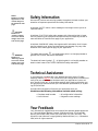
Safety Information
We use note, caution and warning symbols throughout this book to draw your
attention to important operational and safety information.
A bold text “NOTE” marks a short message in the margin to alert you to an
important detail.
A bold text “CAUTION” safety alert appears with information that is important for protecting your equipment and performance. Be especially careful to
read and follow all cautions that apply to your application.
A bold text “WARNING” safety alert appears with information that is important for protecting you, others and equipment from damage. Pay very close
attention to all warnings that apply to your application.
ÓWARNING:
Details of a
“Warning” appear
here in the narrow
margin on the outside of each page.
The safety alert symbol, ç, (an exclamation point in a triangle) precedes a
general CAUTION or WARNING statement.
The electrical hazard symbol, Ó, (a lightning bolt in a triangle) precedes an
electric shock hazard CAUTION or WARNING safety statement.
Technical Assistance
If you encounter a problem with your Watlow controller, see the Troubleshooting Table on page 6.5 first, review all of your configuration information to
verify that your selections are consistent with your application: inputs; outputs; alarms; limits; etc. If the problem persists after checking the above, you
can get technical assistance from your local Watlow representative, or by dialing (507) 454-5300.
An applications engineer will discuss your application with you.
Please have the following information available when calling:
• Complete model number
• All configuration information
• User’s Manual
• Diagnostic menu readings
Your Feedback
Your comments or suggestions on this manual are welcome, please send them
to: Technical Writer, Watlow Controls, 1241 Bundy Blvd., P.O. Box 5580,
Winona, MN 55987-5580, Phone: (507) 454-5300, Fax: (507) 452-4507. The
MicroDIN User’s Manual is copyrighted by Watlow Winona, Inc., © December
1996, with all rights reserved.
Watlow MicroDIN iii
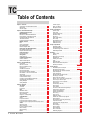
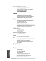
TC
Table of Contents
Chapter 1: Overview ......................................................................... 1.1
Introduction to the MicroDIN Controller .................................. 1.2
Setup Steps ............................................................................. 1.3
Indicator Lights ........................................................................ 1.3
Chapter 2: Communications Setup ................................................... 2.1
Communications Overview ..................................................... 2.2
EIA-485 Network ..................................................................... 2.3
Elements of a MicroDIN 485 Network ...................................... 2.3
PC Connection via 232/485 Converter ..................................... 2.3
Special Case 485 Considerations ............................................. 2.4
Termination Resistor ............................................................... 2.4
Pull-Up and Pull-Down Resistors ............................................ 2.4
Modbus™ Protocol ................................................................... 2.5
RTU ......................................................................................... 2.5
Access via Registers ................................................................ 2.5
MicroDIN Supports .................................................................. 2.5
Modbus™ Register Table ........................................................... 2.6
DIP Switches Set Address/Baud Rate ..................................... 2.7
MicroDIN DIP Switch Table ..................................................... 2.7
Required Parameters Setup ..................................................... 2.8
Serial Data Format ................................................................. 2.9
Data Format Table .................................................................... 2.9
Wiring Tasks ........................................................................... 2.9
Wiring Task List ....................................................................... 2.9
Communications Software ...................................................... 2.9
Watlow’s WatLink .................................................................... 2.9
Other Software Options ........................................................... 2.9
Chapter 3: Installation Wiring .......................................................... 3.1
Introduction ............................................................................. 3.2
Set DIP Lower First................................................................... 3.2
Mount on DIN Rail or Tabs ...................................................... 3.2
Wire Unit I/O............................................................................. 3.2
Installation Accessories ........................................................... 3.2
Mount the MicroDIN ................................................................ 3.3
Mount the MicroDIN on a DIN Rail .......................................... 3.4
MicroDIN RJ-11 and 10-Pin Connectors ................................. 3.5
Input Wiring ............................................................................. 3.6
Output and Power Wiring ........................................................ 3.7
Communications Wiring .......................................................... 3.8
Convertor-To-MicroDIN Wiring Example ................................. 3.8
Special EIA-485 Considerations ............................................... 3.9
Wiring Examples .................................................................... 3.10
Wiring Examples .................................................................... 3.11
Chapter 4: Features .......................................................................... 4.1
The System ............................................................................. 4.2
Auto-tune ................................................................................. 4.2
Power Limit ............................................................................. 4.3
Input ........................................................................................ 4.4
Calibration Offset ..................................................................... 4.4
Filter Time Constant ................................................................. 4.5
Sensor Selection ...................................................................... 4.6
Range Low or Range High ....................................................... 4.6
Control Methods ...................................................................... 4.7
On/Off ...................................................................................... 4.7
Proportional Control ................................................................ 4.8
Proportional plus Integral (PI) Control ..................................... 4.9
Proportional plus Integral plus Derivative (PID) Control ........ 4.10
Alarms ................................................................................... 4.11
Alarm Set Points .................................................................... 4.11
Alarm Hysteresis .................................................................... 4.11
Process or Deviation Alarms .................................................. 4.12
Alarm Latching ...................................................................... 4.12
Alarm Silencing ...................................................................... 4.13
Errors ..................................................................................... 4.14
iv Watlow MicroDIN
Indicator Lights ...................................................................... 4.14
Open Loop Detect .................................................................. 4.14
Bumpless Transfer ................................................................. 4.15
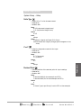
Chapter 5: Parameters ..................................................................... 5.1
System Group .......................................................................... 5.2
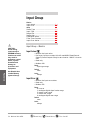
Input Group ............................................................................. 5.4
Control Output Group .............................................................. 5.8
Operation Group .................................................................... 5.11
PID Group .............................................................................. 5.13
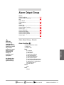
Alarm Output Group ............................................................... 5.17
Error Group ............................................................................ 5.22
Characteristics Group ............................................................ 5.25
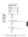
Diagnostics Group ................................................................. 5.27
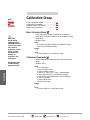
Calibration Group ................................................................... 5.30
Chapter 6: Operations ...................................................................... 6.1
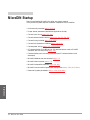
Startup MicroDIN ..................................................................... 6.2
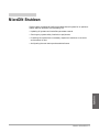
MicroDIN Shutdown ................................................................ 6.3
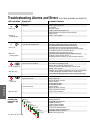
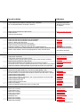
Troubleshooting: Alarms and Errors................................. 6.4 - 6.5
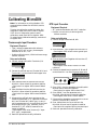
Calibrating MicroDIN ............................................................... 6.6
Appendix .......................................................................................... A.1
Modbus™ RTU .......................................................................... A.2
Glossary .................................................................................. A.8
Declaration of Conformity ...................................................... A.12
Specifications ........................................................................ A.14
Ordering Information.............................................................. A.15
Index ..................................................................................... A.16
Parameter Index .................................................................... A.18
Required Parameters Setup Order ......................................... A.19
Warranty Information .................................................. Back Cover
Figures by page
MicroDIN Inputs and Outputs .................................... Figure 1.2
MicroDIN Indicator Lights .................................................... 1.3
MicroDIN Top View with DIP Switches ................................. 2.1
Figure Description ................................................................ 2.1
Figure Description ................................................................ 2.1
Mounting a MicroDIN Controller ........................................... 3.2
Mounting on a DIN rail ........................................................ 3.3a
Dismounting off a DIN rail .................................................. 3.3b
Bottom view of case with pin assignments ........................... 3.4
Control Input, Thermocouple .............................................. 3.5a
Control Input, 2 and 3-wire RTD ......................................... 3.5b
Control Input ....................................................................... 3.6a
Internal Output Circuitry ..................................................... 3.6b
Alarm Output ...................................................................... 3.6c
Power Wiring ...................................................................... 3.6d
Converter-to-MicroDIN Wiring Example ............................... 3.7
Termination for MicroDIN ..................................................... 3.9
System Wiring Example ...................................................... 3.10
System Wiring Example ...................................................... 3.11
Auto-tuning ........................................................................... 4.2
Power Limits ........................................................................ 4.3
Calibration Offset .................................................................. 4.4
Filtered and Unfiltered Input Signals ..................................... 4.5
Sensor Ranges ..................................................................... 4.6
On/Off Control for Cooling and Heating ................................ 4.7
Proportional Control ............................................................. 4.8
Proportional plus Integral Control ........................................ 4.9
PID Control ......................................................................... 4.10
Alarm Settings .................................................................... 4.11
Alarm Latching ................................................................... 4.12
Alarm Silencing .................................................................. 4.13
Error Information ................................................................ 4.14
Calibrating diagrams ............................................................. 6.6
Overview
1
Chapter One:
Overview
Introduction to the MicroDIN Controller .. 1.2
Setup Steps ............................................. 1.3
Indicator Lights ....................................... 1.3
Watlow MicroDIN 1.1
Overview
Introduction to the MicroDIN Controller
The Watlow MicroDIN controller is a DIN rail-mounted, temperature controller.
It uses one input and two outputs, network connections and dozens of
parameters to satisfy a broad variety of control needs.
The single input can use either a thermocouple or RTD sensor. The single
control output provides an open collector or switched dc output signal for a
power switching device with a DC input. The single alarm output is an
electromechanical relay. The network connections allow as many as 32
controllers to be configured and monitored from a single personal computer.
You can configure, operate and monitor the MicroDIN almost entirely from a
PLC or personal computer via a serial connection using RJ-11 jacks. Indicator
lights on the face of the controller monitor error states, power, communications
activity and output activity.
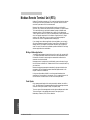
Communications Input and Output
to and from Personal Computer
MicroDIN
MicroDIN
MicroDIN
MicroDIN
Temperature Controller
Temperature Controller
Temperature Controller
Temperature Controller
Address
Power
Power
Power
Comms
Comms
Comms
Power
Comms
Control
Output
Control
Output
Control
Output
Control
Output
Alarm
Alarm
Alarm
Alarm
Input
Error
Input
Error
Input
Error
Input
Error
1
Address
2
Address
3
Address
4
1-32 devices/
EIA-485 Network
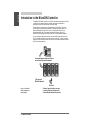
Figure 1.2 - MicroDIN
inputs and outputs in a
thermal system
1.2 Watlow MicroDIN
Per Unit:
• Sensor Input from the process
• Control Output to the process
• Alarm Output about the process
Overview
Setup Steps
1. Set up communications.
2. Set the controller’s address and baud speed with the DIP switches on the top
panel (see Chapter 2, Communications Setup). The controller uses eight data
bits with no parity.
3. Mount the controller (see Chapter 3, Wiring).
4. Wire the controller (see Chapter 3, Wiring).
5. Communicate with MicroDIN via an EIA-485 network with Modbus™
RTU protocol.
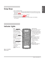
Indicator Lights
Power
Green light stays
lit when the power is on
and the controller is ok.
• If it isn’t on or pulsates,
check your power source.
MicroDIN
Temperature Controller
Power
Control Output
Green light is lit or flashes
when the control output is
energized.
• If it does not light up, the
output is not turning on.
Alarm
Red Light is lit during an
input alarm condition.
If it is lit:
• Correct alarm condition
or change alarm
configuration.
• Reset the alarm if it is
latched.
Comms
Control
Output
Communications
Green Light pulsates when the
controller sends or receives
valid data over its network port.
• If it does not light up, check
the controller address and the
communications setup.
Input Error
Red Light is lit if there is a
sensor problem. If it is lit:
• Verify the sensor wiring,
polarity and function.
• Rewire or replace as
necessary.
Alarm
Input
Error
Address Field
Record the unit’s address in
erasable marker here.
Address
Figure 1.3 - MicroDIN
indicator lights
Watlow MicroDIN 1.3
Overview
Notes
1.4 Watlow MicroDIN
Chapter Two:
Communications Setup
Communications Overview
EIA-485 Network ............................... 2.2
Modbus™ Protocol ............................. 2.2
Set Address/Baud Rate .......................2.2
Serial Data Format ............................. 2.2
Wiring Tasks ...................................... 2.2
Communications Software ................. 2.2
EIA-485 Network
Elements of a MicroDIN 485 Network 2.3
PC Connection via 232/485 Converter 2.3
Special Case 485 Considerations ....... 2.4
Termination Resistor .......................... 2.4
Pull-Up and Pull-Down Resistors ...... 2.4
Modbus Protocol
RTU ................................................... 2.5
Access via Registers .......................... 2.5
MicroDIN Supports... ......................... 2.5
Modbus™ Register Table .................... 2.6
DIP Switches Set Address/Baud Rate
MicroDIN DIP Switch Table ............... 2.7
Required Parameters Setup ............... 2.8
Serial Data Format
Data Format Table .............................. 2.9
Wiring Tasks
Wiring Task List ................................. 2.9
Communications Software
Watlow’s WatLink .............................. 2.9
Other Software Options ..................... 2.9
Watlow MicroDIN 2.1
Communications
Setup
2
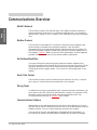
Communications Overview
EIA-485 Network
Communication
Setup
The MicroDIN uses the EIA-485 (formerly, ÒRS-485Ó) hardware interface to
communicate with three wires in a half-duplex configuration, up to 32 remote
devices with a master unit on a network up to 4,000 feet long using 14-26 gauge
wire.
Modbus Protocol
The MicroDIN uses Modbusª RTU protocol to read and write to registers that
can be viewed or changed from a personal computer. Each MicroDIN
ÔparameterÕ has a corresponding Modbusª register and access privileges. The
MicroDIN parameter register numbers and the order of priority appear later in
this chapter. Chapter 5 details all the MicroDIN parameters, and the Appendix
provides information on how to write custom Modbusª applications
Set Address/Baud Rate
You must configure the communications speed and network address of the
MicroDIN controller with the eight-bit DIP switch on the top of the unit. Set the
controller address with the first six switches and the network speed (9,600 or
19,200 baud) with the eighth switch. Turn to the DIP switch page later in this
chapter.
Serial Data Format
The MicroDIN uses the an 8-N-1 data format; 8 data bits, no parity, 1 stop bit,
and 1 start bit. See the data format table later in this chapter.
Wiring Tasks
In addition to wiring the controllerÕs input, outputs and power connections, you
must also wire the EIA-232-to-EIA-485 converter; connect your computer to the
MicroDIN, and connect the MicroDIN communications daisy chain. See
ÒCommunications WiringÓ in Chapter 3 for full detail.
Communications Software
Watlow offers a Windows application for MicroDIN, called, ÒWatLink,Ó which
will both set up and run multiple MicroDINs over an EIA-485 network using the
Modbusª protocol. Turn to a screen sample at the end of this chapter.
You may also write your own application (see Appendix for more detail), or
purchase any of several available Modbusª-capable control software packages.
2.2 Watlow MicroDIN
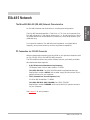
EIA-485 Network
An EIA-485 interface uses three wires in a half-duplex configuration.
The EIA-485 standard specifies a T+/R+ line; a T-/R- line; and a common line.
EIA-485 interprets a -5 volt signal <None> as a 1, a +5-volt signal as a 0. Up to
32 remote devices can be connected to a master on a multi-drop network up to
4,000 feet long.
For industrial networks, EIA-485 offers low impedance, a multiple-device
capability, strong noise immunity and the long distance capability.
PC Connection via 232/485 Converter
Watlow recommends connecting the MicroDIN to your personal computers with
an EIA-232 (RS-232) to EIA-485 (RS-485) converter.
The 232-to-485 converters are proven reliable, low cost, and readily available.
We recommend these suppliers:
•
B & B Electronics Manufacturing Company
707 Dayton Road, PO Box 1040, Ottawa, IL 61350
Tel: (815) 433-5100; Fax: (815) 434-7094; Web: http://www.bb-elec.com
Request part number: 485OIC with a power supply and the correct 25-pin
gender connector for your computer.
•
CMC (Connecticut microComputer, Inc.)
P.O. Box 186, Brookfield, CT 06804
Tel: (800) 426-2872, (203) 740-9890; Fax: (203) 775-4595
Request part number: ADA485L with the correct 25-pin gender connector
for your computer.
See Chapter 3 for wiring details.
Watlow MicroDIN 2.3
Communications
Setup
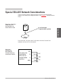
The MicroDIN EIA-485 (RS-485) Network Characteristics
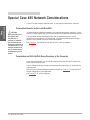
Special Case 485 Network Considerations
If your EIA-485 network does not work, it may require termination resistors.
Communication
Setup
Termination Resistor at the Last MicroDIN
çCAUTION:
Apply termination and
pull-up/pull-down
resistors only if
necessary to establish
data communications.
Adding this resistance to
a network where it is not
required could result in
loss of communications
and damage to process
product.
In some cases long distance networks may require termination resistors. If the
continuity checks good and you still cannot get valid responses, add termination.
You can make a terminator by placing a 120½ resistor across the C and D
terminals of a standard RJ-11 phone plug. Plug the terminator into the open
socket in the furthest MicroDIN from the computer.
See Chapter 3, ÒInstallation and Wiring,Ó for a wiring diagram.
Termination and Pull-Up/Pull-Down Resistors at the Converter
If you use a terminator, you should also add pull-up and pull-down resistors to
the EIA-485 converter box.
Place a 120-ohm resistor across the transmit/receive terminals (C and D) of the
converter box.
Add 1K½ pull-up and pull-down resistors as shown in Chapter 3 to maintain the
correct voltage during the idle state.
See Chapter 3 for wiring diagram.
2.4 Watlow MicroDIN
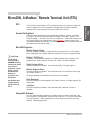
MicroDIN, A Modbus™ Remote Terminal Unit (RTU)
The MicroDIN uses Modbus™ RTU (remote terminal unit) protocol to read and
write to registers that can be viewed or changed from a personal computer.
Sending ASCII text commands to the MicroDIN will not work.
Access Via Registers
Each MicroDIN parameter has a corresponding Modbus™ register and access
privileges. The value of each parameter is stored in a Modbus™ register. The
access privilege — read only, write only or read/write — determines whether you
can change and/or view a parameter’s value. Chapter 5 explains some of the
interactions between parameters. The tables at the end of this chapter show the
parameters and their setup order.
MicroDIN Supports...
Multiple Register Reads
MicroDIN supports Modbus™ Commands 03 and 04 read of a 1- to 32-register
block. Responses from -1999 to 9999 are valid data for up to 32 register writes.
çCAUTION:
Avoid writing
continuously to
EEPROM memory.
Continuous writes
may result in
premature control
failure, system
downtime and
damage to
processes and
equipment.
Modbus™ 32000 Errors
A Modbus™ read command response of -32000 indicates that a register is not
implemented; -32001, register not active; or -32002, not read accessible.
Single Register Writes
MicroDIN supports a Modbus™ write command (06) to a single register.
Multiple Register Writes
MicroDIN supports a Modbus™ write command (16) for multiple writes as long
as the data length is 1.
Writing to address 0 broadcasts to all devices on the network.
Write Exceptions
See Disable Nonvolatile Memory
(System Group),
Ch. 5.
MicroDIN supports write exceptions: 01, illegal function; 02, illegal register; 03,
illegal data.
Loop Back
MicroDIN supports a Modbus™ write command 08, “loop back” to echo a
message.
Compatible Software
You will need compatible software to interact with a MicroDIN controller. One
such program is included with the MicroDIN Startup Kit. If you are accustomed
to using a Modbus™, see the Appendix for information to help write your own
Modbus™ software application.
Watlow MicroDIN 2.5
Communications
Setup
RTU
Modbus Register Numbers
Communication
Setup
Address
Address
Absolute Relative Parameters
Absolute Relative Parameters
40001
0
Model Number (Diagnostics)
40602
601
Input Type (Input)
40002
1
Serial Number (Characteristics)
40603
602
Range Low (Input)
40003
2
Serial Number 2 (Characteristics)
40604
603
Range High (Input)
40004
3
Software ID number (Characteristics)
40605
604
Filter Time Constant (Input)
40005
4
Software Revision (Characteristics)
40606
605
Calibration Offset (Input)
40006
5
Date of Manufacture (Characteristics)
40607
606
Decimal Point (System)
40007
6
Ship Date (Characteristics )
40608
607
Error Clearing Mode (Error)
40017
16
Control Output Hardware (Control Output)
40701
700
Control Output Function (Control Output)
40018
17
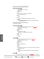
Alarm Output Hardware (Alarm)
40714
713
Power Limit Set Point (Control Output)
40025
24
Disable Non-volatile Memory (System)
40715
714
High Side Power (Control Output)
40101
100
Input Actual (Input)
40716
715
Low Side Power (Control Output)
40102
101
Input Error (Input)
40718
717
Alarm Output Function (Alarm Output)
40104
103
Output Power (Control Output)
40720
719
Alarm Type (Alarm Output)
40107
106
Alarm Condition (Alarm Output)
40721
720
Alarm Hysteresis (Alarm Output)
40201
200
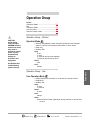
Operation Mode (Operation)
40722
721
Alarm Latching Mode (Alarm Output)
40205
204
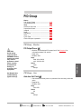
PID Output Power (PID)
40723
722
Alarm Silencing Mode (Alarm Output)
40206
205
Proportional Term (PID)
40724
723
Alarm Active Sides (Alarm Output)
40207
206
Integral Term (PID)
40725
724
Alarm Logic (Alarm Output)
40208
207
Derivative Term (PID)
40901
900
Units Type (System)
40210
209
System Error (Error)
40902
901
C or F (System)
40211
210
Open Loop Error (Error)
40903
902
Input Error Action (Input)
40301
300
Set Point (Operation)
40904
903
Fixed Manual Output (Control Output)
40302
301
User Operation Mode (Operation)
40905
904
Activate Open Loop Detect (Error)
40305
304
Auto-tune Set Point (PID)
41501
1500
Ambient (CJC) Temperature (System)
40306
305
Initiate Auto-tune (PID)
41502
1501
Ambient (CJC) A-to-D Counts (Diagnostics)
40311
310
Manual Output Power (Operation)
41503
1502
RTD Lead Compens. A-to-D Counts (Diag)
40312
311
Clear Error (Error)
41504
1503
RTD Lead Resistance (Diagnostics)
40322
321
Alarm Low (Alarm Output)
41505
1504
Input A-to-D Counts (Diagnostics)
40323
322
Alarm High (Alarm Output)
41513
1512
Enter Diagnostics Mode (Diagnostics)
40332
331
Clear Alarm (Alarm Output)
41514
1513
Test Displays (Diagnostics)
40333
332
Silence Alarm (Alarm Output)
41515
1514
Test Outputs (Diagnostics)
40501
500
Proportional Band (PID)
41601
1600
Enter Calibration Mode (Calibration)
40502
501
Integral (PID)
41602
1601
Restore to Factory Calibration (Calibration)
40503
502
Reset (PID)
41603
1602
Reset Factory Defaults (Calibration)
40504
503
Derivative (PID)
41604
1603
Calibration Commands (Calibration)
40505
504
Rate (PID)
40507
506
Cycle Time (PID)
40508
507
Control Output Hysteresis (PID)
40601
600
Sensor Type (Input)
2.6 Watlow MicroDIN
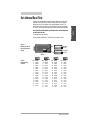
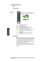
Configure the communications speed and network address of the MicroDIN
controller with the eight-bit DIP switch on the top panel. Set the controller
address with the first six switches. Set an address between 1 and 63. The
network will not work correctly if any two controllers have the same address.
DIP switch 1 sets the left-most binary digit. Switch 6 sets the right-most digit.
Record the MicroDIN’s address in erasable marker on the white space
on the front of the unit.
The seventh switch has no effect.
Set the network speed (9,600 or 19,200 baud) with the eighth switch.
Figure 2.7 MicroDIN top view with
DIP switches and baud
settings
O
N
↑
O
N
↑
1 2 3 4 5 6 7 8
9600 baud
(bit 8 on)
1 2 3 4 5 6 7 8
19.2k baud
(bit 8 off)
1 2 3 4 5 6 7 8
O
N
↑
Top View
O
N
↑
Table 2.7 Decimal-to-binary
conversion
Dec.
1
2
3
4
5
6
7
8
9
10
11
12
13
14
15
1 2 3 4 5 6 7 8
Binary
000001
000010
000011
000100
000101
000110
000111
001000
001001
001010
001011
001100
001101
001110
001111
O
N
↑
Dec.
16
17
18
19
20
21
22
23
24
25
26
27
28
29
30
31
1 2 3 4 5 6 7 8
Binary
010000
010001
010010
010011
010100
010101
010110
010111
011000
011001
011010
011011
011100
011101
011110
011111
O
N
↑
Dec.
32
33
34
35
36
37
38
39
40
41
42
43
44
45
46
47
1 2 3 4 5 6 7 8
Binary
100000
100001
100010
100011
100100
100101
100110
100111
101000
101001
101010
101011
101100
101101
101110
101111
O
N
↑
Dec.
48
49
50
51
52
53
54
55
56
57
58
59
60
61
62
63
1 2 3 4 5 6 7 8
Binary
110000
110001
110010
110011
110100
110101
110110
110111
111000
111001
111010
111011
111100
111101
111110
111111
Watlow MicroDIN 2.7
Communications
Setup
Set Address/Baud Rate
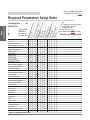
Note: This table also appears
inside the back cover, p. A.19
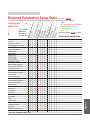
Required Parameters Setup Order
This table provides 1) the correct order of entry, 2) the effect of a parameter change, and 3) a place to document settings.
Parameters
should be set
up in this order.
Uni
ts T
ype
Co
rF
Con
trol
Out
Sen
put
sor
Fun
T
ctio
y
p
Inpu
e
n
t Ty
p
e
Ran
ge
Ran Low
ge H
igh
Hig
hS
ide
Low
Pow
er
Side
P
Alar
o
w
mT
er
Ope ype
rati
Dec on Mod
im a
e
l
çCAUTION:
➝
➝
Communication
Setup
Changing this ➝
Affects this
Units Type
C or F
Input Error Action
Control Output Function
Set Fixed Manual Output
Open Loop Detect
Sensor Type
Input Type
Range Low
C
Range High
C
Decimal Point
Calibration Offset
C
Filter Time Constant
Error Clearing Mode
Power Limit Set Point
C
High Side Power
Low Side Power
Alarm Output Function
Alarm Type
Alarm Hysteresis
C
Alarm Latching Mode
Alarm Silencing Mode
Alarm Active Sides
Alarm Logic
Alarm High
C
Alarm Low
C
Propband
C
Integral
O
Reset
O
Derivative
Rate
Cycle Time
Output Hysteresis
C
Operation Mode
Set Point
Manual Output Power
Set Point
C
Table 2.8 - Parameters Setup order.
Watlow MicroD IN 2.8
O
O
D
D
D
D
D
D
D
D
D
D
C
C
D D
C
D D
D D
C
C
O
O
D D
D D
D D
O
O
C
C
C
D D
O
C
O O
D D O O
O
C
Key:
D = Changing will change the default
C = Changing will convert the
temperature scale
O = Other effect (see Ch. 5)
(See Parameter Index, p. A.18, for detail)
Document your settings below
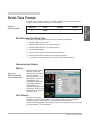
Serial Data Format
Table 2.9a Serial Data Format
Data Bits
Parity
Stop Bit
Start Bit
8
None
1
1
MicroDIN Installation Wiring Tasks
MicroDIN requires these wiring tasks for a successful installation
1. Wire MicroDIN sensor input.
2. Wire MicroDIN Output 1, the control output.
3. Wire MicroDIN Output 2, the alarm output.
4. Wire MicroDIN power.
5. Connect the MicroDIN communications daisy chain.
6. Wire the 232-to-485 converter; connect to the computer.
7. If necessary, wire the termination and pull-up/pull-down resistors.
Communications Software
WatLink
Figure 2.9b WatLink for MicroDIN
sample software screen
Watlow offers a Modbus™
package in WatLink,
software that will set up
and run multiple
MicroDINs over an EIA485 network. WatLink,
a Windows 3.31 or
Windows 95 application,
is available from any
Watlow sales representative or authorized
distributor. WatLink can
handle up to 32 different
MicroDIN units.
Other Software
To communicate with
MicroDIN, you must use a Modbus™ RTU (remote terminal unit) compatible
software package. Sending ASCII commands via a standard serial
communication application will not work. Refer to the Appendix if you’re writing
your own Modbus™ RTU application.
Watlow MicroDIN 2.9
Communications
Setup
Configure your computer’s COM1 or COM2 (communications) port data format
to match the MicroDIN’s settings in the table below.
Notes
Communication
Setup
2.10 Watlow MicroDIN
Installation and Wiring ■
3
Install and Wire
Chapter Three:
Installation and Wiring
Introduction
Set DIPs First ......................................3.2
Mount on DIN Rail Tabs...................... 3.2
Wire Unit I/O .......................................3.2
Installation Accessories ..................... 3.2
Mounting the MicroDIN .......................... 3.3
Mounting the MicroDIN on a DIN Rail ... 3.4
MicroDIN RJ-11 and 10-pin Connectors 3.5
Input Wiring ............................................ 3.6
Output and Power Wiring ....................... 3.7
Communications Wiring ......................... 3.8
Converter-To-MicroDIN Wiring Example 3.8
Special EIA-485 Considerations ............. 3.9
Wiring Example .................................... 3.10
Wiring Example .................................... 3.11
Watlow MicroDIN 3.1
Introduction
For a successful MicroDIN installation you need to cover the tasks cited in the
subheads below. If you do all these things and the MicroDIN doesn’t work, go to
the troubleshooting chart in Chapter 6.
Set DIP Switch First
If you haven’t done it already, set the controller’s address and baud speed with
the DIP switches on the top of the unit (see Chapter 2, Communications Setup).
The controller uses eight data bits with no parity, and 1 stop bit.
Mount on DIN Rail or Tabs
Install and Wire
Mount the controller(s) either on an EN 50022 35mm x 7.5mm DIN rail or with
the built-in mounting tabs.
Wire Unit I/O
Wire the MicroDIN’s input, output, communications and power connections
using the diagrams in this chapter.
Installation Accessories
0219-0218-0000 Included, 6-inch communications cable (RJ-11, 4-conductor,
straight through)
0836-0445-0000 Included, 10-pin removable connector with screw terminals
Not Included:
0219-0217-0000 7-foot communications cable (RJ-11, 4-conductor, straight
through)
0830-0473-0000 Communications converter (EIA-232 to EIA-485)
0830-0474-0000 Power supply (120VÅ (ac) input, 24VÎ (dc) output)
3.2 Watlow MicroDIN
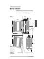
Mounting the MicroDIN
To mount a MicroDIN on a DIN rail, hook the upper lip of the rail mounting
bracket onto the rail and press the controller down until the bottom lip of the
mount snaps onto the rail. To remove, as you push the back of the controller
down lift the front up until the bottom lip unsnaps from the rail.
To mount a MicroDIN on a panel, use the dimensions below to drill screw holes
for the mounting bracket.
bracket for
panel mounting
(#6 screw
or m3.5 required)
.318 in
(8 mm)
Top/bottom
mount
hole offset
Side View
Install and Wire
Figure 3.3 Mounting a MicroDIN
controller.
MicroDIN
Temperature Controller
Power
4.225 in
(107 mm)
3.750 in
(146 mm)
Comms
Control
Output
DIN
rail
4.650 in
(118 mm)
Alarm
Input
Error
Front View
Address
5.062 in
(129 mm)
Min. Clearance
between rail
centerlines
5.750 in
(146 mm)
Min. Clearance 2 in
(51 mm)
1.637 in
(42 mm)
2.875 in
(73 mm)
MicroDIN
MicroDIN
Temperature Controller
Temperature Controller
Power
Power
DIN
rail
ç
CAUTION:
Maintain the correct
spacing between rows of
controllers to allow
sufficient air circulation
and installation
clearance. Failure to do
so could result in
damage to equipment.
Address
Comms
Comms
Control
Output
Control
Output
Alarm
Alarm
Input
Error
Input
Error
Address
1.650 in
(42 mm)
Attachment Angle
10°
Use DIN EN 50022 35mm x 7.5mm Rail
Watlow MicroDIN 3.3
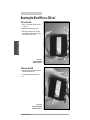
Mounting the MicroDIN on a DIN rail
To Mount MicroDIN
1. Push unit in and down to catch rail hook
on top of rail.
2. Rotate bottom of unit in toward rail.
①
3. Rail clasp will audibly “snap” into place.
If the MicroDIN does not snap into place,
check to see if the rail is bent.
Install and Wire
Figure 3.4a Mounting a MicroDIN
controller on a DIN rail.
➂ "Snap"
➁
To Dismount MicroDIN
1. Press down on back of controller until the
bottom hook clears the rail.
①
2. Then rotate bottom up and away from
rail.
➁
Figure 3.4 bDismounting a MicroDIN
controller from a DIN rail.
3.4 Watlow MicroDIN
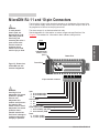
MicroDIN RJ-11 and 10-pin Connectors
WARNING:
To avoid potential
electric shock, use
National Electric Code
(NEC) safety practices
when wiring and
connecting this unit to a
power source and to
electrical sensors or
peripheral devices.
Failure to do so could
result in injury or death.
Figure 3.5 - Bottom view
of MicroDIN case with
connector assignments.
The alarm output is an electromechanical relay.
See the Appendix for information on sensor ranges and specifications. See
Chapter 5: Parameters for information about software configuration.
ABCD
communications
sockets 1 and 2
(RJ-11)
Front of Unit
Install and Wire
Ó
The MicroDIN 10-pin screw terminal connector, on the bottom of the case, links
it to its power supply, control input, control output and alarm output. Use 26- to
14-gauge wire to connect to the plug terminals.
Bottom View
1
2
3
4
5
6
7
8
9
10
1 2 3 4 5 6 7 8 9 10
10-pin removable connector
ç
WARNING:
Install high or low
temperature limit control
protection in systems
where an over
temperature fault
condition could present a
fire hazard or other
hazard. Failure to install
temperature limit control
protection where a
potential hazard exists
could result in damage to
equipment and property
and injury to personnel.
Input
1. S1 or thermocouple+
2. S3 or thermocouple3. S2
Control Output
4. dc+
5. dc6. common (COM)
Alarm Output (electromechanical relay)
7. alarm normally open (NO)
8. alarm common (COM)
Power
9. L2, 24V‡ (ac/dc)10. L1, 24V‡ (ac/dc)+
Watlow MicroDIN 3.5
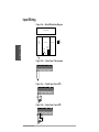
Input Wiring
Figure 3.6a — MicroDIN Isolation Diagram
Power Supply
Safety
Isolation
Logic
and
Input
Outputs
UL/CE
Comms
500V
Noise
Isolation
Install and Wire
Control
Output
Alarm
Figure 3.6b — Control Input, Thermocouple
1 2 3 4 5 6 7 8 9 10
+
-
Figure 3.6c — Control Input, 2-wire RTD
1 2 3 4 5 6 7 8 9 10
S1 S3
Figure 3.6d — Control Input, 3-wire RTD
1 2 3 4 5 6 7 8 9 10
S1
S2
S3
3.6 Watlow MicroDIN
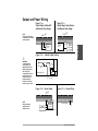
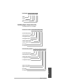
Output and Power Wiring
Figure 3.7b —
Control Output, Open Collector
with External Power Supply
dc
+
dc
C
O
M
1 2 3 4 5 6 7 8 9 10
1 2 3 4 5 6 7 8 9 10
+
External
External
External
Switching
Load
Device
External
Switching
Device
Load
-
-
+
+
Power
Supply
60V max.
1A max.
Figure 3.7c — Internal Output Circuitry
Ó
WARNING:
To avoid potential
electric shock, use
National Electric Code
(NEC) safety practices
when wiring and
connecting this unit to a
power source and to
electrical sensors or
peripheral devices.
Failure to do so could
result in injury or death.
+24VÎ(dc)
2KΩ
20Ω
Internal Circuitry
4
dc+
5
6
dc- COM
Figure 3.7d — Alarm Output
N
.O
C .
O
M
Figure 3.7e — Power Wiring
1 2 3 4 5 6 7 8 9 10
1 2 3 4 5 6 7 8 9 10
Fuse
NOTE:
Relay suppression
required only for
inductive loads.
Relay
Suppression
L1
24V‡ (ac/dc)
External
Load
- +
L2
Watlow MicroDIN 3.7
Install and Wire
NOTE:
The current limit feature
is disabled in this version
of the controller.
dc
+
dc
C
O
M
Figure 3.7a —
Control Output, Switched DC
with Internal Power Supply
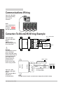
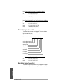
Communications Wiring
Figure 3.8a - MicroDIN
communications daisy
chain via RJ-11
connectors.
MicroDIN
MicroDIN
MicroDIN
MicroDIN
Temperature Controller
Temperature Controller
Temperature Controller
Temperature Controller
Power
Power
Address
Power
Power
Comms
Comms
Comms
Comms
Control
Output
Control
Output
Control
Output
Control
Output
Alarm
Alarm
Alarm
Alarm
Input
Error
Input
Error
Input
Error
Input
Error
1
Address
2
Address
Address
3
4
Converter-To-MicroDIN Wiring Example
RJ-11 to MicroDIN
3.8 Watlow MicroDIN
120V~
G
9VDC
G
B
A
B
A
DI/O DI/O
EIA-485
ADA485L
120VÅ (Vac)
9ÎVdc (see NOTE)
Comms Plug
Yellow
Red
Green
Yellow
0219-0217-0000
7 ft. comms cable
NOTE:
The CMC converter requires an external power supply when used with a laptop.
AB CD
Figure 3.8c - CMC
Converter to MicroDIN
Wiring
(CMC Connecticut MicroComputer, Inc.
Ph. 800-426-2872)
EIA-485
+
– Power Supply
AD-1210
AB CD
Ó
WARNING:
To avoid potential electric
shock, use National
Electric Code (NEC) safety
practices when wiring and
connecting this unit to a
power source and to
electrical sensors or
peripheral devices.
Failure to do so could
result in injury or death.
Green
Yellow
TD (A)
TD (B)
RD (A)
RD (B)
TD (A)
TD (A)
SIG GND
EIA-485
EIA-232
Figure 3.8b- B&B
Converter to MicroDIN
Wiring
(B&B Electronics
Manufacturing Company,
Ph. 815-433-5100)
EIA232
Install and Wire
NOTE:
If your network doesn’t
function, see Chapter 2
for special
EIA- 485 considerations.
Special EIA-485 Network Considerations
Figure 3.9 a- Termination
for MicroDIN; RJ-11
phone plug with 120Ω
resistor across C and D
ABCD
RJ-11 Terminals
C (green) and D (yellow)
120Ω
Plug terminator into open socket in MicroDIN controller furthest from
computer, the last unit on the network.
Figure 3.9b Termination for
EIA-232/EIA-485
Converter with pull-up
and pull-down resistors.
+5V
Converter box
termination
with pull-up
and pull-down
resistors.
B
T+/R+
A
T-/R-
GND
Com
1KΩ
120Ω
1KΩ
Watlow MicroDIN 3.9
Install and Wire
If your MicroDIN network needs termination and pull-up and pull-down
resistors, wire them per the diagrams below. See Chapter 2, “Communications
Setup.”
Wiring Examples
Ó
Install and Wire
WARNING:
To avoid potential
electric shock, use
National Electric Code
(NEC) safety practices
when wiring and
connecting this unit to a
power source and to
electrical sensors or
peripheral devices.
Failure to do so could
result in injury or death.
L1
120VÅ (ac)
L2
Branch
Circuit Fuse
Earth Ground
20A
1A
Watlow
MicroDIN
Temperature
Controller
UD1A-CES-0000
1A
High Limit
Mechanical
Contactor
Coil
0830-0474-0000
Power Supply 17-8020 Semiconductor
Fuse
L1
12345 6789
L2
Heater
Thermocouples
EIA485
Loop
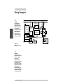
Figure 3.10 System wiring example,
schematic.
ç
WARNING:
Install high or low
temperature limit control
protection in systems
where an over
temperature fault
condition could present a
fire hazard or other
hazard. Failure to install
temperature limit control
protection where a
potential hazard exists
could result in damage to
equipment and property
and injury to personnel.
3.10 Wa tlow MicroDIN
High
temp.
light
92A3-1DJ1-DC
DIN-a-mite
DA1C-1624-C000
T2
T1
1 2 3 4 5 6 7 8 9 10
EIA485 to RS232
Converter
R
5A
PC
OR
ModBus
Converter
Limit Control
10 11 121314 151617
Optional
Normally
Open
Momentary
Switch
Ó
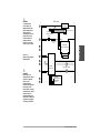
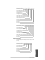
Figure 3.11 System wiring example,
ladder diagram.
120V~(ac)
L1
1
3
1
+
4
L2
0830-0474-0000
Supply
3 Power
2
– +
–
5
1
2
6
3
Loop
PC
EIA485 EIA485
4
5
8
6
7
2
10
1
MicroDIN
UD1A-1CES-0000
9 10
9
11
11
Semiconductor
Fuse
2
9
4
8
+
2
L2
L1
3
DIN-a-mite
DA1C-1624-C000
–
T1
T2
92A3-1DJ1-DC
5
12
1
2
–
+ 15
16
10
11
1
18
4
20
9
10
13
2
2
1 CR
3
2
17
92 Series
Limit Control
8
Heater
14
1
7
WARNING:
Install high or low
temperature limit control
protection in systems
where an over
temperature fault
condition could present a
fire hazard or other
hazard. Failure to install
temperature limit control
protection where a
potential hazard exists
could result in damage to
equipment and property
and injury to personnel.
2
1CR-1
6
ç
8
7
Install and Wire
WARNING:
To avoid potential
electric shock, use
National Electric Code
(NEC) safety practices
when wiring and
connecting this unit to a
power source and to
electrical sensors or
peripheral devices.
Failure to do so could
result in injury or death.
High Temp. Light
5
13
14
21
19
2
Optional
Normally Open
Momentary
Switch
Watlow MicroDIN 3.11
Notes
Install and Wire
3.12 Wa tlow MicroDIN
4
Chapter Four:
Features
Features
The System
Auto-tune ........................................... 4.2
Power Limit ....................................... 4.3
Input
Calibration Offset ............................... 4.4
Filter Time Constant ........................... 4.5
Sensor Selection ................................ 4.6
Range Low and Range High .............. 4.6
Control Methods
On/Off ................................................ 4.7
Proportioned Control ......................... 4.8
Proportioned plus Integral (PI)
Control ............................................... 4.9
Proportioned plus Integral
plus Derivative (PID) Control ........... 4.10
Alarms
Alarm Set Points .............................. 4.11
Alarm Hysteresis ............................. 4.11
Process or Deviation Alarms ........... 4.12
Alarm Latching ................................ 4.12
Alarm Silencing ............................... 4.13
Errors
Indicator Lights ............................... 4.14
Open Loop Detect ............................ 4.14
Bumpless Transfer ........................... 4.15
Watlow MicroDIN 4.1
The System
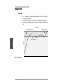
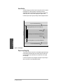
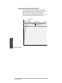
Auto-tune
Auto-tuning allows the controller to explore the responsiveness of the system in
order to determine an effective set of parameters for PID control. To do this it
crosses an auto-tune set point five times, then controls at the normal set point
using the new parameters.
Use Auto-tune Set Point (PID Group) to select the temporary set point, as a
percentage of the normal set point, that the controller will tune to. Initiate or
cancel the auto-tune process with Auto-tune (PID Group). The default value is
90%.
Process Set Point
Auto-tune initiated by user
Auto-tune complete
Features
Temperature
Auto-tune Set Point
(default 90% of process set point)
Time
Figure 4.2 — Auto-tuning
4.2 Watlow MicroDIN
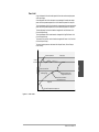
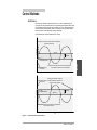
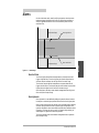
Power Limit
A high side power limit and low side power limit set the maximum output power
within two ranges
A low side power limit limits the output to a percentage of the maximum output
power while the process temperature or value is below the power limit set point.
The high side power limit limits the output to a percentage of the maximum output
power while the process temperature or value is above the power limit set point.
The low side power limit can be viewed or changed with Low Side Power Limit
(Control Output Group).
The high side power limit can be viewed or changed with High Side Power Limit
(Control Output Group).
The power limit set point can be viewed or changed with Power Limit Set Point
(Control Output Group).
The actual output power can be viewed with Output Power (Control Output
Power Group).
Range High
Process temperature
with no power limit
Features
Temperature
Process
Set Point
Power Limit Set Point
(between Range Low
and Range High)
Output Power switches
to High Side Power Limit
Output Power is limited to
Low Side Power Limit
Range Low
Process Temperature with power limit
Time
Figure 4.3 — Power Limits
Watlow MicroDIN 4.3
Input
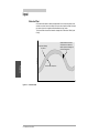
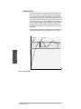
Calibration Offset
Calibration offset allows a device to compensate for an inaccurate sensor, lead
resistance or other factors that affect the input value. A positive offset increases
the input value, and a negative offset decreases the input value.
The input offset value can be viewed or changed with Calibration Offset (Input
Group).
Negative Calibration Offset will
compensate for the difference
between the Sensor Reading and
the Actual Temperature.
Temperature
Temperature Reading
from Sensor
Features
Actual Process Temperature
Time
Figure 4.4 — Calibration Offset
4.4 Watlow MicroDIN
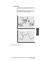
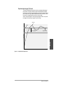
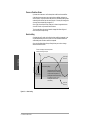
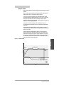
Filter Time Constant
A time filter smooths an input signal by sampling the input at designated time
intervals. Either the viewed value or both the viewed and control values can be
filtered.
View or change the time filter with Filter Time Constant (Input Group). A
positive value affects only the viewed values. A negative value affects both the
viewed and control values. The filter is a single pole low pass.
Temperature
Unfiltered Input Signal
Features
Time
Temperature
Filtered Input Signal
Time
Figure 4.5 — Filtered and Unfiltered Input Signals
Watlow MicroDIN 4.5
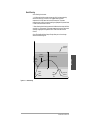
Sensor Selection
You need to configure a controller to match the input device, which is normally a
thermocouple or RTD. When you select an input device the controller
automatically sets the input linearization to match the sensor. It also sets high
and low limits, which in turn limit the range high and range low values.
Use Sensor Type and Input Type (Input Group) to select the appropriate sensor.
High Limit of selected Sensor Range
Range High Range (between High Limit of Sensor and Range Low)
Temperature
Range High
Set Point Range (must be between Range High and Range Low)
Range Low
Range Low Range (between Low Limit of Sensor and Range High)
Features
Low Limit of selected Sensor Range
Time
Figure 4.6 — Sensor Ranges
Range Low and Range High
The controller constrains the set point to a value between range high and range
low. Range high cannot be set higher than the sensor high limit or lower than
range low. Range low cannot be set lower than the sensor low limit or higher
than range high.
Use Set Point (Operation Group), Range High and Range Low (Input Group) to
select or view values for the corresponding parameters.
4.6 Watlow MicroDIN
Control Methods
On/Off Control
On/off control switches the output either full on or full off, depending on the
input, set point and hysteresis values. The hysteresis value creates a buffer zone
that increases the time interval that the output is off or on. With hysteresis set
to 0 the process value would stay closer to the set point, but the output would
switch on and off more frequently, causing “chattering.”
Set hysteresis with Output Hysteresis (PID Group).
Temperature
Heating Action switches off when the Process Temperature
rises above the Set Point
Set Point
Hysteresis
Heating Action switches
on at Startup
Heating Action switches on when the Process Temperature
drops below the Set Point minus the Hysteresis
Time
Temperature
Cooling Action Switches on when the
Cooling Action switches Process Temperature rises above the
on at Startup
Set Point plus the Hysteresis
Process Temperature
Hysteresis
Set Point
Cooling Action Switches off when the Process Temperature
drops below the Set Point
Time
Figure 4.7 — On/Off Control for Heating and Cooling
Watlow MicroDIN 4.7
Features
Process Temperature
Proportional Control
Some processes need to maintain a temperature or process value closer to the
set point than on/off control can provide. Proportional control provides closer
control by adjusting the output when the temperature or process value is within
a proportional band. When the value is in the band, the controller adjusts the
output based on how close the process value is to the set point: the closer to set
point the lower the output. This is similar to backing off on the gas pedal of a
car as you approach a stop sign. It keeps the temperature or process value from
swinging as widely as it would with simple on/off control. However, when a
system settles down, the temperature or process value tends to “droop” short of
the set point.
The proportional band can be viewed or changed with Propband (PID Group). To
only view the proportional control value use Proportional Term (PID Group).
Set Point
Overshoot
Features
Temperature
Proportional Band
Time
Figure 4.8 — Proportional Control
4.8 Watlow MicroDIN
Droop
Proportional plus Integral (PI) Control
The droop caused by proportional control can be corrected by adding integral
(reset) control to the system. When the system has settled down the integral
(reset) value is tuned to bring the temperature or process value closer to the set
point. However, this may increase the overshoot that occurs at startup or when
the set point is changed. Used more with fast, high loss loads.
View or change the integral or reset value with Integral or Reset. To only view
the integral control value use Integral Term (PID Group).
Overshoot
Set Point
Droop Corrected
Features
Temperature
Proportional Band
Time
Figure 4.9 — Proportional plus Integral Control
C
Watlow MicroDIN 4.9
Proportional plus Integral plus Derivative (PID) Control
Use derivative (rate) control to minimize the overshoot in a PI-controlled
system. Derivative (rate) adjusts the output based on the rate of change in the
temperature or process value. Used more with slow, lagging loads.
View or change derivative or rate with Derivative or Rate (PID Group). To only
view the derivative control value use Derivative Term (PID Group).
Reduced Overshoot
Set Point
Temperature
Proportional Band
Features
Time
Figure 4.10 — PID Control
4.10 Watlow MicroDIN
Alarms
An alarm takes some action, usually notifying an operator, when the process
temperature leaves a defined range. A user can configure how and when an
alarm is triggered and whether it turns off automatically when the alarm
condition is over.
High Side Alarm Range
Alarm High Set Point
Temperature
Alarm Hysteresis
Normal Operating Range
Alarm Hysteresis
Alarm Low Set Point
Features
Low Side Alarm Range
Time
Figure 4.11 — Alarm Settings
Alarm Set Points
The alarm high set point defines the temperature or process value that will
trigger a high side alarm. The alarm high set point must be higher than the
alarm low set point and lower than the high limit of the sensor range.
The alarm low set point defines the temperature or process value that will
trigger a low side alarm. The alarm low set point must be lower than the alarm
high set point and higher than the low limit of the sensor range.
Alarm set points or deviation can be viewed or changed with Alarm High and
Alarm Low (Alarm Output Group).
Alarm Hysteresis
Alarm hysteresis is a zone defined by adding an hysteresis value to the alarm
low set point or subtracting the hysteresis value from the alarm high set point.
Once an alarm has occurred it will not clear until the process value is above the
alarm-low setting or below the alarm-high settings by a margin equal to the
hysteresis. Example: An alarm starts when the process value reaches the alarm
high setting. The alarm will not clear until it is below the high setting by an
amount equal to or greater than the alarm hysteresis.
The alarm hysteresis value can be viewed or changed with Alarm Hysteresis
(Alarm Output Group).
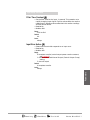
Watlow MicroDIN 4.11
Process or Deviation Alarms
A process alarm uses one or two fixed set points to define an alarm condition.
A deviation alarm uses one or two set points that are defined relative to the
control set point. High and low alarm set points are calculated by adding and/or
subtracting offset values from the control set point. If the set point changes, the
alarm set points automatically change with it.
Alarm Type (Alarm Output Group) allows you to view or change whether the
alarm will function as a process or deviation alarm.
The alarm deviation value can be viewed or changed with Alarm High and
Alarm Low (Alarm Output Group).
Alarm Latching
A latched alarm will remain active after the alarm condition has passed. It can
only be deactivated by the user. An alarm that is not latched will deactivate
automatically when the alarm condition has passed.
Alarm Latching Mode (Alarm Output Group) allows you to view or change
whether an alarm will latch.
The alarm state begins when the temperature
reaches the alarm high set point.
Alarm High
Set Point
Temperature
Features
Normal Operating Range
Process
Temperature
The alarm state continues until the
temperature drops to the alarm high
set point minus the hysteresis. A
latching alarm could be turned off by
the operator at this point. A nonlatching alarm would turn off
automatically.
Alarm Low
Set Point
Time
Figure 4.12 — Alarm Latching
4.12 Watlow MicroDIN
Alarm Silencing
Alarm silencing has two uses:
1. It is often used to allow a system to warm up after it has been started up.
With alarm silencing on, an alarm is not triggered when the process
temperature is initially lower that the alarm low set point. The process
temperature has to enter the normal operating range beyond the hysteresis zone
in order to activate the alarm function.
2. Alarm silencing also allows the operator to disable the alarm output while the
controller is in an alarm state. The process temperature has to enter the normal
operating range beyond the hysteresis zone in order to activate the alarm
function.
Alarm Silencing Mode (Alarm Output Group) allows you to view or change
whether alarm silencing is on.
Process
Temperature
Normal Operating Range
Alarm
enabled
here
Features
Temperature
Alarm High
Set Point
Startup,
Alarm
disabled
Alarm
triggered
here
Alarm Low
Set Point
Time
Figure 4.13 — Alarm Silencing
Watlow MicroDIN 4.13
Errors
Panel Indicator Lights
Figure 4.14 - Error
Information
MicroDIN
Temperature Controller
Power
Error Information — Unison Green/Red Flashing Code
ERROR 4 5 6 7 11 12 13 14 15
Comms
Control
Output
Alarm
Input
Error
Address
Features
Error
Error
Error
Error
Error
Error
Error
4
5
6
7
11
12
13
Error 14
Error 15
RAM malfunction (return to factory)
EEPROM data corrupted
PROM malfunction (return to factory)
SPI failure, onboard peripheral hardware not responding
New software installed (cycle power to correct)
Cal EEROM checksum, calibration data corrupted (recalibrate)
A-to-D hardware fail, A-to-D hardware not responding
(return to factory)
EEROM hardware fail, EEPROM peripheral not responding
(return to factory)
New unit, displays on first power up (return to factory)
Open Loop Detect
Open loop detect can alert the user of trouble on the input or output side of the
control loop. An open loop error is triggered when 100 percent power is applied
at the control output for a period of time equal to the setting of integral (PID
Group), or when reset without the input registering a 5° (F or C) change.
If an open loop error occurs, shut down the system, check the input and control
output wiring and check the input and output devices.
The open loop detect feature can be turned on or off with Activate Open Loop
Detect (Error Group). Use Open Loop Error (Error Group) to check for an open
loop condition.
4.14 Watlow MicroDIN
Bumpless Transfer
When the sensor opens (fails), the MicroDIN switches from automatic to manual
operation.
When transferring from automatic to manual operation, the control output, or
outputs, remain stable — a bumpless, or smooth, transition.
If the Input Error Action parameter is set to 0, bumpless transfer, and the
process has stabilized at a power level less than 75% ( ± 5%) for a two-minute
period prior to the sensor break, then the MicroDIN switches to manual
operation at the last automatic power level. If these conditions are not met, the
output goes to 0% power (output disabled).
If the Input Error Action parameter is set to Fixed Manual Output, the
MicroDIN switches to manual operation at the Fixed Manual Output percent
power value.
Manual operation provides open-loop control of the outputs from a range of
-100% to 100% output. The MicroDIN allows a negative output value only when
Output 1 is set to cool.
Automatic operation provides closed-loop on/off or PID control. When the
operator transfers from a closed loop to an open loop, the MicroDIN sets the
power level to the setting of the Input Error Action parameter. If Input Error
Action is set to 0, bumpless transfer, the controller retains the power level from
the closed-loop control. When the MicroDIN returns to closed-loop control, it
restores the previous set point process value.
Features
Figure 4.15 — Bumpless Transfer
Temperature
Set Point
Actual Temperature
Tie
Break
Power
100%
Output Power
≤75% power
2 min.
0%
Locks in
Output
Power
Time
Watlow MicroDIN 4.15
Notes
Features
4.16 Watlow MicroDIN
5
Chapter Five
Learn the Parameters
System Group ............5.2 PID Group................5.13 Characteristics Group..5.25
Input Group ...............5.4
Input Actual (100) .......................... 5.4
Input Error (101) ............................ 5.4
Sensor Type (600) ........................... 5.5
Input Type (601) ............................. 5.5
Range Low (602) ............................. 5.6
Range High (603)............................ 5.6
Calibration Offset (605) ................. 5.6
Filter Time Constant (604) ............ 5.7
Input Error Action (902) ................ 5.7
Control Output Group....5.8
Output Power (103) ........................ 5.8
Control Output Hardware (16)...... 5.8
Control Output Function (700)...... 5.8
Power Limit Set Point (713) .......... 5.9
High Side Power (714) ................... 5.9
Low Side Power (715)................... 5.10
Fixed Manual Output (903) ......... 5.10
PID Output Power (204) .............. 5.13
Auto-tune Set Point (304) ............ 5.13
Initiate Auto-tune (305) ............... 5.14
Proportional Band (500)............... 5.14
Integral (501) ................................ 5.14
Reset (502) .................................... 5.15
Derivative (503) ............................ 5.15
Rate (504)...................................... 5.15
Cycle Time (506) ........................... 5.16
Control Output Hysteresis (507) . 5.16
Alarm Output Group....5.17
Alarm Condition (106).................. 5.17
Alarm Output Hardware (17)...... 5.18
Clear Alarm On/Off (331)............. 5.18
Silence Alarm On/Off (332).......... 5.18
Alarm Low (321)........................... 5.19
Alarm High (322) ........................ 5.19
Alarm Output Function (717)...... 5.20
Alarm Type (719).......................... 5.20
Alarm Hysteresis (720) ................ 5.20
Alarm Active Sides (723).............. 5.20
Alarm Latching Mode (721)......... 5.21
Alarm Silencing Mode (722) ........ 5.21
Alarm Logic (724) ......................... 5.21
Error Group ..............5.22
Operation Group ........5.11
Operation Mode (200)................... 5.11
User Operation Mode (301).......... 5.11
User Set Point (300) ..................... 5.12
Manual Output Power (310) ........ 5.12
Date of Manufacture (5)............... 5.25
Ship Date (6)................................. 5.25
Serial Number 1 (1)...................... 5.25
Serial Number 2 (2)...................... 5.26
Software ID Number (3) .............. 5.26
Software Revision (4) ................... 5.26
Diagnostics Group......5.27
Model Number (0) ........................ 5.27
Ambient (CJC) A-to-D Counts (1501) 5.27
Input A-to-D Counts (1504) ........ 5.27
RTD Lead Compensation Analog-toDigital Counts (1502) .............. 5.28
RTD Lead Resistance (1503) ....... 5.28
Proportional Term (205)............... 5.28
Integral Term (206) ...................... 5.28
Derivative Term (207) .................. 5.29
Enter Diagnostics Mode (1512) ... 5.29
Test Displays (1513) ..................... 5.29
Test Outputs (1514)...................... 5.29
Calibration Group ......5.30
Enter Calibration Mode (1600)....
Calibration Commands (1603).....
Restore to Factory
Calibration (1601)....................
Reset Factory Defaults (1602) .....
5.30
5.30
5.31
5.31
Open Loop Error (210) ................. 5.22
Open Loop Detect (904)................ 5.22
Input Error (101) .......................... 5.23
System Error (209) ....................... 5.23
Clear Error (311) .......................... 5.23
Input Error Action (902) .............. 5.24
Error Clearing Mode (607)........... 5.24
Watlow MicroDIN 5.1
Parameters
Ambient (CJC) Temperature (1500) . 5.2
Non-volatile Memory (24) .............. 5.2
Units Type (900) ............................. 5.3
C or F (901) ..................................... 5.3
Decimal Point (606)........................ 5.3
System Group continued
System Group
Monitor
Ambient (CJC) Temperature .................... 5.2
Use
Non-volatile Memory ................................. 5.2
Setup
Units Type ................................................. 5.3
C or F ......................................................... 5.3
Decimal Point ............................................ 5.3
ç
CAUTION:
Avoid writing
continuously to
EEPROM memory.
Continuous writes
may result in
premature control
failure, system
downtime and
damage to
processes and
equipment.
See Disable Nonvolatile Memory
(System Group).
System Group – Monitor
System Error
• See Error Group.
Ambient (CJC) Temperature
• Read the ambient temperature in 0.1 degrees Fahrenheit.
• Read only
• Modbus: 1500
Range
0.0 to 180.0 F
Default
none
Active
always
Parameters
System Group – Use
Non-volatile Memory
• Disable storage of parameters to non-volatile (EEPROM) memory.
This allows you to change parameters frequently without wearing
out the memory.
• Read/write
• Modbus: 24
Range
0: store parameters when they are changed
1: do not store parameters when they are changed
Default
0 (always reverts to 0 when the controller’s power is turned off
and on)
Active
always
Affects
all parameters
will not save any parameters when set to 1.
5.2 Watlow MicroDIN
=Read Only;
= Read/Write;
ON
= Turn On/Off
System Group continued
System Group – Setup
Units Type
• Select US or SI units of measurement.
• Read/write
• Modbus: 900
Range
0: US (reciprocate integral term)
1: SI (reciprocate integral term)
Default
0: US
Active
always
Affects
Propband, Integral and Reset (PID Group)
converts Reset and Integral (changes span to degrees or vice
versa)
C or F
Decimal Point
• Sets the position of the decimal point for input readings.
• Read/write
• Modbus: 606
Range
0: decimal 0000 (for thermocouple and RTD)
1: decimal 000.0 (for for thermocouple and RTD)
Default
0
Active
if Sensor Type (Input Group) is set to RTD or thermocouple
=Read Only;
= Read/Write;
ON
= Turn On/Off
Watlow Micr oDIN 5.3
Parameters
• Select the temperature scale for the input.
• Read/write
• Modbus: 901
Range
0: F (Fahrenheit)
1: C (Celsius)
Default
0: F
Active
always
Input Group
Monitor
Input Actual ............................................... 5.4
Input Error ................................................ 5.4
Setup
Sensor Type ............................................... 5.5
Input Type ................................................. 5.5
Range Low ................................................. 5.6
Range High ................................................ 5.6
Calibration Offset ...................................... 5.6
Filter Time Constant ................................ 5.7
Input Error Action ..................................... 5.7
ç
CAUTION:
Avoid writing
continuously to
EEPROM memory.
Continuous writes
may result in
premature control
failure, system
downtime and
damage to
processes and
equipment.
Parameters
See Disable Nonvolatile Memory
(System Group).
Input Group – Monitor
Input Actual
• Monitor the input value.
• During an input error state, this will read 9999 if Read Control
Output (Control Output Group) is set to heat or -1999 if it is set to
cool.
• Read only
• Modbus: 100
Range
input type range
Default
none
Active
always
Input Error
• Monitor the input error status.
• Read only
• Modbus: 101
Range
0: no error
1: analog-to-digital signal under range
2: sensor under range
3: sensor over range
4: analog-to-digital over range
Default
none
Active
always
5.4 Watlow MicroDIN
=Read Only;
= Read/Write;
ON
= Turn On/Off
Input Group continued
Input Group – Setup
Sensor Type
• Select the input sensor type.
• Read/write
• Modbus: 600
Range
0: thermocouple
1: RTD
Default
0: thermocouple
Active
always
Affects
Changes Input Type (Input Group) to J for thermocouple, DIN
for RTD, and defaults temperature related parameters.
• Set the linearization for the input sensor.
• Read/write
• Modbus: 601
Range
if Sensor Type (Input Group) set to thermocouple
0: J
1: K
2: T
3: E
4: N
5: C
6: D
7: PT2
8: R
9: S
10: B
if Sensor Type (Input Group) set to RTD
11: RTD_DIN
12: RTD_JIS
Default
if Sensor Type (Input Group) is changed to thermocouple: J
if Sensor Type (Input Group) is changed to RTD: DIN
Active
always
Affected by
Changing Sensor Type sets to J for thermocouple, DIN for RTD,
and defaults temperature related parameters
=Read Only;
= Read/Write;
ON
= Turn On/Off
Watlow Micr oDIN 5.5
Parameters
Input Type
Input Group continued
Range Low
• Set the input range low. This setting is the lowest value that the
set point can have.
• Read/write
• Modbus: 602
Range
see Sensor Table in the Appendix for sensor ranges and defaults
Default
see Sensor Table in the Appendix for sensor ranges and defaults
Active
always
Affects
Set Point (Operation Group) limits the set point to the range
between Range Low and Range High (Input Group)
Range High
• Set the input range high. This setting is the highest value that the
set point can have.
• Read/write
• Modbus: 603
Range
see Sensor Table in the Appendix for sensor ranges and defaults
Default
see Sensor Table in the Appendix for sensor ranges and defaults
Active
always
Affects
Set Point (Operation Group) limits the set point to the range
between Range Low and Range High (Input Group)
Parameters
Calibration Offset
• Set the input calibration offset. This allows you to compensate for
lead resistance, sensor errors and other factors.
• Read/write
• Modbus: 605
Range
-1999 to 9999
Default
0
Active
always
5.6 Watlow MicroDIN
=Read Only;
= Read/Write;
ON
= Turn On/Off
Input Group continued
Filter Time Constant
• Set the filter time for the input, in seconds. This smooths out a
rapidly changing input signal. Positive values affect the monitor
readings only. Negative values affect both the monitor readings
and the control values.
• Read/write
• Modbus: 604
Range
-60.0 to 60.0
Default
0.0
Active
always
Input Error Action
Parameters
• Select how the controller responds to an input error.
• Read/write
• Modbus: 902
Range
0: bumpless transfer (control output power remains constant,
see Chapter 5)
1: switch to the Fixed Manual Output (Control Output Group)
setting
2: shut off output
Default
0: bumpless transfer
Active
always
=Read Only;
= Read/Write;
ON
= Turn On/Off
Watlow Micr oDIN 5.7
Control Output Group
Monitor
Output Power .............................................. 5.8
Control Output Hardware .......................... 5.8
Setup
Control Output Function ............................ 5.8
Power Limit Set Point ................................. 5.9
High Side Power .......................................... 5.9
Low Side Power ........................................... 5.9
Fixed Manual Output ................................ 5.10
ç
CAUTION:
Avoid writing
continuously to
EEPROM memory.
Continuous writes
may result in
premature control
failure, system
downtime and
damage to
processes and
equipment.
Parameters
See Disable Nonvolatile Memory
(System Group).
Control Output Group – Monitor
Output Power
• Monitor the control output power level. This can limit PID Output
Power (PID Group).
• Read only
• Modbus: 103
Range
heat: 0.0 to 100.0
cool: -100.0 to 0.0
Default
none
Active
always
Control Output Hardware
• Read the control output hardware type.
• Read only
• Modbus: 16
Range
3: dc
Default
3
Active
always
Control Output Group – Setup
Control Output Function
• Select whether the control output will control for heating or
cooling.
• Read/write
• Modbus: 700
5.8 Watlow MicroDIN
=Read Only;
= Read/Write;
ON
= Turn On/Off
Control Output Group continued
Range
0: heat
1: cool
Default
0: heat
Active
always
Affects
Manual Output Power (Operation Group) determines heat or
cool values.
High Side Power, Low Side Power or Fixed Manual Output
(Control Output Group) changes range
Power Limit Set Point
• Select the set point that High Side Power and Low Side Power
(Control Output Group) will use to limit the control output range.
• Read/write
• Modbus: 713
Range
Range Low to Range High (Input Group) values
Default
Range High
Active
always
• Set the maximum allowed power above the Power Limit Set Point
(Control Output Group).
• Read/write
• Modbus: 714
Range
heat: 0.0 to 100.0
cool: -100.0 to 0.0
Default
heat: 100.0
cool: -100.0
Active
always
Affected by
Changing Control Output Function (Control Output Group)
changes range.
=Read Only;
= Read/Write;
ON
= Turn On/Off
Watlow Micr oDIN 5.9
Parameters
High Side Power
Control Output Group continued
Low Side Power
• Set the maximum allowed power below the Power Limit Set Point
(Control Output Group).
• Read/write
• Modbus: 715
Range
heat: 0.0 to 100.0
cool: -100.0 to 0.0
Default
heat: 100.0
cool: -100.0
Active
always
Affected by
Changing Control Output Function (Control Output Group)
changes range
Fixed Manual Output
Parameters
• Select the initial control output power to take effect when the
controller is switched to manual mode by either the user or an
error.
• Read/write
• Modbus: 903
Range
heat: 0.0 to 100.0
cool: -100.0 to 0.0
Default
0.0
Active
always
Affected by
Changing Control Output Function (Control Output Group)
changes range
5.10 Watlow MicroDIN
=Read Only;
= Read/Write;
ON
= Turn On/Off
Control Output Group continued
Operation Group
Monitor
Operation Mode ......................................... 5.11
Use
Operation Mode ......................................... 5.11
User Set Point ........................................... 5.12
Manual Output Power .............................. 5.12
CAUTION:
Avoid writing
continuously to
EEPROM memory.
Continuous writes
may result in
premature control
failure, system
downtime and
damage to
processes and
equipment.
Operation Group – Monitor
Operation Mode
• Monitor the operation mode. Normally follows the user selected
mode. It returns to the previous state after an error clears.
• Read only
• Modbus: 200
Range
0: off
1: auto
2: manual control (user selected)
3: manual control (due to error)
Default
auto
Active
always
See Disable Nonvolatile Memory
(System Group).
Operation Group – Use
User Operation Mode
• Select whether the controller is under auto or manual control.
• Read/write
• Modbus: 301
Range
0: auto
1: manual
Default
0: auto
Active
always
Affects
Manual Output Power (Operation Group) manual or manual due
to error
=Read Only;
= Read/Write;
ON
= Turn On/Off
Watlow Micro DIN 5.11
Parameters
ç
Operation Group continued
User Set Point
• Change or monitor the control set point.
• Read/write
• Modbus: 300
Range
Range Low to Range High (Input Group)
Default
75°F, 24°C
Active
if Operation Mode (Operation Group) is set to auto
Affected by
Changing Sensor Type (Input Group) determines range of setting
and default
Changing Input Type (Input Group) determines range of setting
and default
Changing Range Low (Input Group) determines range of setting
and default
Changing Range High (Input Group) determines range of setting
and default
Changing C or F (System Group) determines range of setting
and default
Manual Output Power
Parameters
• Set the control output power manually.
• Read/write
• Modbus: 310
Range
0.0 to 100.0: heat mode
-100.0 to 0.0: cool mode
Default
0.0
Active
if Operation Mode (Operation Group) is set to manual or
switches to manual due to error
Affected by
Changing Operation Mode (Operation Group) to manual or
manual due to error
Changing Control Output Function (Alarm Output Group)
determines range of setting
5.12 Watlow MicroDIN
=Read Only;
= Read/Write;
ON
= Turn On/Off
PID Group
Monitor
PID Output Power ..................................... 5.13
Initiate Auto-tune ...................................... 5.14
Setup
Auto-tune Set Point .................................. 5.13
Proportional Band ..................................... 5.14
Integral ...................................................... 5.14
Reset ........................................................... 5.15
Derivative .................................................. 5.15
Rate ............................................................ 5.15
Cycle Time ................................................. 5.15
Control Output Hysteresis ....................... 5.16
PID Group – Monitor
PID Output Power
• Monitor the calculated PID power level. See Chapter 4 for
information about PID control.
• Read only
• Modbus: 204
Range
heat: 0.0 to 100.0
cool: -100.0 to 0.0
Default
none
Active
always
CAUTION:
Avoid writing
continuously to
EEPROM memory.
Continuous writes
may result in
premature control
failure, system
downtime and
damage to
processes and
equipment.
See Disable Nonvolatile Memory
(System Group).
PID Group – Use
Auto-tune Set Point
• Set the auto-tune set point as a percent of the currently active set
point.
• Read/write
• Modbus: 304
Range
50 to 150
Default
90
Active
always
=Read Only;
= Read/Write;
ON
= Turn On/Off
Watlow Micro DIN 5.13
Parameters
ç
PID Group continued
Initiate Auto-tune
• Initiate or cancel an auto-tune.
• Read/write
• Modbus: 305
Range
0: off or cancel an auto-tune in progress
1: initiate an auto-tune
Default
0: off
Active
if Operation Mode (Operation Group) is set to auto
Affected by
Changing Operation Mode (Operation Group) available when
mode is set to auto
PID Group – Setup
Proportional Band
Parameters
• Set the proportional band for PID control. See Chapter 4 for
information about PID control.
• Read/write
• Modbus: 500
Range
0: on/off control mode
1-9999°F or °C: proportional control mode
Default
25ºF, 17ºC
Active
always
Integral
• Set the integral time for PID control. See Chapter 4 for
information about PID control.
• Read/write
• Modbus: 501
Range
0.00 to 99.99 minutes
Default
0.00
Active
if Propband (PID Group) is not set to 0 and Units Type (System
Group) is set to SI
Affected by
Changing Units Type (System Group) will convert Integral to
Reset.
Reset
• Set the reset time for PID control. See Chapter 4 for information
5.14 Watlow MicroDIN
=Read Only;
= Read/Write;
ON
= Turn On/Off
PID Group continued
about PID control.
• Read/write
• Modbus: 502
Range
0.00 to 99.99 minutes per repeat
Default
0.00
Active
if Propband (PID Group) is not set to 0 and Units Type (System
Group) is set to US
Affected by
Changing Units Type (System Group) will convert Integral to
Reset.
Derivative
• Set the derivative time for PID control. See Chapter 4 for
information about PID control.
• Read/write
• Modbus: 503
Range
0.00 to 9.99 minutes
Default
0.00
Active
if Propband (PID Group) is not set to 0 and Units Type (System
Group) is set to SI
• Set the rate time for PID control. See Chapter 4 for information
about PID control.
• Read/write
• Modbus: 504
Range
0.00 to 9.99 minutes
Default
0.00
Active
if Propband (PID Group) is not set to 0 and Units Type (System
Group) is set to US
=Read Only;
= Read/Write;
ON
= Turn On/Off
Watlow Micro DIN 5.15
Parameters
Rate
PID Group continued
Cycle Time
• Set the control output cycle time in seconds.
• Read/write
• Modbus: 506
Range
0.1 to 60.0 seconds
Default
2.0
Active
if Propband (PID Group) is not set to 0 and Units Type (System
Group) is set to US
Control Output Hysteresis
• Set the control output switching hysteresis.
• Read/write
• Modbus: 507
Range
1 to 9999°F or °C
Default
3
Active
only if Propband is set to 0
Parameters
5.16 Watlow MicroDIN
=Read Only;
= Read/Write;
ON
= Turn On/Off
PID Group continued
Alarm Output Group
Monitor
Alarm Condition ........................................ 5.17
Alarm Output Hardware .......................... 5.17
Use
Clear Alarm ............................................... 5.18
Silence Alarm ............................................ 5.18
Setup
Alarm Low ................................................. 5.18
Alarm High ................................................ 5.19
Alarm Output Function ............................ 5.19
Alarm Type ................................................ 5.19
Alarm Hysteresis ....................................... 5.20
Alarm Active Sides .................................... 5.20
Alarm Latching Mode ............................... 5.20
Alarm Silencing Mode ............................... 5.21
Alarm Logic ............................................... 5.21
CAUTION:
Avoid writing
continuously to
EEPROM memory.
Continuous writes
may result in
premature control
failure, system
downtime and
damage to
processes and
equipment.
Alarm Output Group – Monitor
Alarm Condition
• Monitor the alarm state.
• Read only
• Modbus: 106
Range
0: no alarm
1: high alarm
2: low alarm
3: high latched alarm
4: low latched alarm
5: high silenced alarm
6: low silenced alarm
7: high latched silenced alarm
8: low latched silenced alarm
9: waiting for in range alarm
10: disabled alarm
11 error alarm
Default
none
Active
always
See Disable Nonvolatile Memory
(System Group).
=Read Only;
= Read/Write;
ON
= Turn On/Off
Parameters
ç
Watlow Micro DIN 5.17
Alarm Output Group continued
Alarm Output Hardware
• Read the alarm output hardware type.
• Read only
• Modbus: 17
Range
1: mechanical relay
Default
1
Active
always
Alarm Output Group – Use
Clear Alarm
ON
• Alarm will clear if alarm condition is resolved
• Read/write
• Modbus: 331
Range
0: no action
1: try to clear a latched alarm
Default
0 (always reverts to 0 after a write)
Active
if Alarm Latching Mode (Alarm Output Group) is set to yes
Silence Alarm
ON
Parameters
• Silence the alarm manually.
• Read/write
• Modbus: 332
Range
0: no action
1: silence alarm
Default
0 (always reverts to 0 after a write)
Active
always
5.18 Watlow MicroDIN
=Read Only;
= Read/Write;
ON
= Turn On/Off
Alarm Output Group continued
Alarm Output Group – Setup
Alarm Low
• Set the low alarm set point.
• Read/write
• Modbus: 321
Range
process: sensor range low to Alarm High (Alarm Output Group)
deviation: -1999 to -1
Default
process: sensor range low
deviation: -1999
Active
if Alarm Output Function (Alarm Output Group) is set to alarm
Affected by
Sensor Type (Input Group) determines range of setting and
default.
Input Type (Input Group) determines range of setting and
default.
Alarm Type (Alarm Output Group) determines range of setting
and default.
C or F (System Group) converts and determines range of setting.
• Set the high alarm set point
• Read/write
• Modbus: 322
Range
process: Alarm Low (Alarm Output Group) to sensor range high
deviation: 1 to 9999
Default
process: sensor range high
deviation: 9999
Active
if Alarm Output Function (Alarm Output Group) is set to alarm
Affected by
Sensor Type (Input Group)
determines range of setting and default
Input Type (Input Group)
determines range of setting and default
Alarm Type (Alarm Output Group)
determines range of setting and default
C or F (System Group)
converts and determines range of setting
=Read Only;
= Read/Write;
ON
= Turn On/Off
Watlow Micro DIN 5.19
Parameters
Alarm High
Alarm Output Group continued
Alarm Output Function
• Turn the alarm output on or off.
• Read/write
• Modbus: 717
Range
0: off
1: alarm
Default
0: off
Active
always
Alarm Type
Parameters
• Select alarm type. A process alarm responds when the temperature
leaves a fixed range. A deviation alarm responds when the
temperature deviates from the set point by a set number of
degrees.
• Read/write
• Modbus: 719
Range
0: process alarm
1: deviation alarm
Default
0: process
Active
if Alarm Output Function (Alarm Output Group) is set to alarm
Affects
Alarm Low (Alarm Output Group) changes to sensor low for
process alarms or -1999 for deviation alarm.
Alarm High (Alarm Output Group) changes to sensor high for
process alarms or 9999 for deviation alarm.
Alarm Hysteresis
• Sets the switching hysteresis for the alarm output. This defines a
band on the inside of the alarm set point. When the process
temperature is in this band, the alarm state will not change.
• Read/write
• Modbus: 720
Range
1 to 9999
Default
3
Active
if Alarm Output Function (Alarm Output Group) is set to alarm
Alarm Active Sides
• Select which side or sides the alarm is active on.
• Read/write
• Modbus: 723
5.20 Watlow MicroDIN
=Read Only;
= Read/Write;
ON
= Turn On/Off
Alarm Output Group continued
Range
0: both
1: high side only
2: low side only
Default
0: both
Active
if Alarm Output Function (Alarm Output Group) is set to alarm
Alarm Latching Mode
• Turn alarm latching on or off. When latching is active, the alarm
will remain on after the alarm condition ends. It must be turned
off manually.
• Read/write
• Modbus: 721
Range
0: no
1: yes
Default
0: no
Active
if Set Alarm Output Function (Alarm Output Group) is set to
alarm
• Turn alarm silencing on or off. When silencing is active and the
controller is first turned on, the alarm cannot become active until
the process temperature leaves the alarm range. Also, alarms can
be manually silenced after one occurs. Entering the normal
operation range resets the silence.
• Read/write
• Modbus: 722
Range
0: no
1: yes
Default
0: no
Active
if Alarm Output Function (Alarm Output Group) is set to alarm
Alarm Logic
• Select alarm output logic.
• Read/write
• Modbus: 724
Range
0: alarm condition de-energizes output (open)
1: alarm condition energizes output (closed)
Default
0
Active
if Alarm Output Function (Alarm Output Group) is set to alarm
=Read Only;
= Read/Write;
ON
= Turn On/Off
Watlow Micro DIN 5.21
Parameters
Alarm Silencing Mode
Error Group continued
Error Group
ç
CAUTION:
Avoid writing
continuously to
EEPROM memory.
Continuous writes
may result in
premature control
failure, system
downtime and
damage to
processes and
equipment.
See Disable Nonvolatile Memory
(System Group).
Monitor
Open Loop Error ........................................ 5.22
Open Loop Detect ...................................... 5.22
Input Error ................................................ 5.22
System Error ............................................. 5.23
Use
Clear Error ................................................ 5.23
Setup
Input Error Action ..................................... 5.24
Error Clearing Mode ................................. 5.24
Error Group – Monitor
Open Loop Error
• Read the open loop error status. An open loop indicates that the
output is not responding appropriately to the input.
• Read only
• Modbus: 210
Range
0: no error
1: open loop error detected
Default
none
Active
always
Parameters
Open Loop Detect
ON
• Turn the open loop detect feature on or off.
• Read/write
• Modbus: 904
Range
0: off
1: on
Default
0: off
Active
always
Affects
Read Open Loop Error (Error Group) must be on to activate
Read Open Loop Error
5.22 Watlow MicroDIN
=Read Only;
= Read/Write;
ON
= Turn On/Off
Error Group continued
Input Error
(see also Input Group)
• Monitor the input error status.
• Read only
• Modbus: 101
Range
0: no error
1: analog-to-digital signal under range
2: sensor under range
3: sensor over range
4: analog-to-digital over signal range
Default
none
Active
always
System Error
Parameters
• Read the system error status.
• Read only
• Modbus: 209
Range
0: no error
4: RAM error
5: non-volatile checksum error
6: PROM error
7: hardware failure
11: software version change
12: calibration checksum error
13: analog-to-digital failure
14: non-volatile hardware failure
15: new unit
Default
none
Active
always
Error Group – Use
Clear Error
• Try to clear a latched input error.
• Read/write
• Modbus: 311
Range
0: no action
1: try to clear latched input error
Default
0 (always reverts after a write)
Active
always
=Read Only;
= Read/Write;
ON
= Turn On/Off
Watlow Micro DIN 5.23
Error Group continued
Error Group – Setup
Input Error Action
(see also Input Group)
• Select how the controller responds to an input error.
• Read/write
• Modbus: 902
Range
0: bumpless transfer (control output power remains constant,
Chapter 4)
1: switch to the Fixed Manual Output (Control Output Group)
setting
2: shut off output
Default
0: bumpless transfer
Active
always
Error Clearing Mode
Parameters
• Set the error clearing mode. When errors are latched, the error
message or indicator persists until it has been cleared manually.
Otherwise the error message or indicator clears automatically
when the condition that caused it no longer exists.
• Read/write
• Modbus: 607
Range
0: not latched (errors clear automatically)
1: latched (errors must be cleared manually)
Default
0: errors clear automatically
Active
always
5.24 Watlow MicroDIN
=Read Only;
= Read/Write;
ON
= Turn On/Off
Characteristics Group continued
Characteristics Group
Date of Manufacture ................................. 5.25
Ship Date ................................................... 5.25
Serial Number 1 ........................................ 5.25
Serial Number 2 ........................................ 5.26
Software ID Number ................................. 5.26
Software Revision ...................................... 5.26
Date Of Manufacture
• Read the manufacture date as week/year (WWYY).
• Read only
• Modbus: 005
Range
0596-9999 (5th week of 1996 to 52nd week of 1999)
Default
none
Active
always
• Read the ship date as week/year (WWYY).
• Read only
• Modbus: 006
Range
0596-9999 (5th week of 1996 to 52nd week of 1999)
Default
none
Active
always
Serial Number 1
• Read the first four digits of the serial number.
• Read only
• Modbus: 001
Range
0-9999
Default
0
Active
always
=Read Only;
= Read/Write;
ON
= Turn On/Off
Watlow MicroDIN 5.25
Parameters
Ship Date
Characteristics Group continued
Serial Number 2
• Read the last four digits of the serial number.
• Read only
• Modbus: 002
Range
0-9999
Default
0
Active
always
Software ID Number
• Read the software ID number.
• Read only
• Modbus: 003
Range
0 to 9999
Default
none
Active
always
Software Revision
Parameters
• Read software revision number.
• Read only
• Modbus: 004
Range
0.00 to 99.99
Default
none
Active
always
5.26 Watlow MicroDIN
=Read Only;
= Read/Write;
ON
= Turn On/Off
Diagnostics Group continued
Diagnostics Group
Model Number ........................................... 5.27
Ambient (CJC) A-to-D Counts .................. 5.27
Input A-to-D Counts .................................. 5.27
RTD Lead Compensation A to D Counts . 5.28
RTD Lead Resistance ................................ 5.28
Proportional Term ..................................... 5.28
Integral Term ............................................. 5.28
Derivative Term ......................................... 5.29
Enter Diagnostics Mode ............................ 5.29
Test Displays ............................................. 5.29
Test Outputs .............................................. 5.29
ç
CAUTION:
Avoid writing
continuously to
EEPROM memory.
Continuous writes
may result in
premature control
failure, system
downtime and
damage to
processes and
equipment.
Model Number
• Read the model number of the controller.
• Read only
• Modbus: 000
Range
8568 (ASCII ‘uD’)
Default
none
Active
always
• Read the raw ambient channel, analog-to-digital signal counts.
• Read only
• Modbus: 1501
Range
0 to 65535
Default
none
Active
always
Input A-to-D Counts
• Read the raw input analog-to-digital converter counts.
• Read only
• Modbus: 1504
Range
0 to 65535
Default
none
Active
always
=Read Only;
= Read/Write;
ON
= Turn On/Off
Watlow MicroDIN 5.27
Parameters
Ambient (CJC) A-to-D Counts
See Disable Nonvolatile Memory
(System Group).
Diagnostics Group continued
RTD Lead Compensation Analog-to-Digital Counts
• Reads the raw, RTD lead compensation, analog-to-digital converter
counts.
• Read only
• Modbus: 1502
Range
0 to 65535
Default
none
Active
always
RTD Lead Resistance
• Reads the measured RTD lead resistance in 0.01 ohms.
• Read only
• Modbus: 1503
Range
0.00 to 99.99
Default
none
Active
always
Proportional Term
Parameters
• Monitor the proportional term. See Chapter 4 for information
about PID control.
• Read only
• Modbus: 205
Range
-100.0 to 100.0
Default
none
Active
always
Integral Term
• Monitor the integral term. See Chapter 4 for information about
PID control.
• Read only
• Modbus: 206
Range
heat: 0.0 to 100.0
cool: -100.0 to 0.0
Default
none
Active
always
5.28 Watlow MicroDIN
=Read Only;
= Read/Write;
ON
= Turn On/Off
Diagnostics Group continued
Derivative Term
• Monitor the derivative term. See Chapter 4 for information about
PID control.
• Read only
• Modbus: 207
Range
-100.0 to 100.0
Default
none
Active
always
Enter Diagnostics Mode (Set)
• Enter the diagnostics mode to test indicator lights and outputs and
to enter the calibration mode.
• Read/write
• Modbus: 1512
Range
0 to 1788 and 1790 to 9999: exit the diagnostics mode
1789: enter the diagnostics mode
Default
0
Active
always
• Test the indicator lights on the front panel.
• Read/write
• Modbus: 1513
Range
0: turn off all indicator lights
1: turn on the cyclic display test
Default
0
Active
if the controller is in the diagnostics mode
Test Outputs
• Test both outputs.
• Read/write
• Modbus: 1514
Range
0: turn both outputs off
1: turn the control output on and the alarm output off
2: turn the control output off and the alarm output on
Default
0
Active
if the controller is in diagnostics mode
=Read Only;
= Read/Write;
ON
= Turn On/Off
Watlow MicroDIN 5.29
Parameters
Test Displays
Calibration Group continued
NOTE:
See page
6.6 for the
calibration
procedures.
Calibration Group
Enter Calibration Mode ............................ 5.30
Calibration Commands ............................. 5.30
Restore Factory Calibration .................... 5.30
Reset Factory Defaults............................... 5.31
Enter Calibration Mode
ç
CAUTION:
Avoid writing
continuously to
EEPROM memory.
Continuous writes
may result in
premature control
failure, system
downtime and
damage to
processes and
equipment.
See Disable Nonvolatile Memory
(System Group).
Parameters
5.30 Watlow MicroDIN
• Enter calibration mode, to calibrate the controller.
• Must be in diagnostics mode to enter calibration mode
• Read/write
• Modbus: 1600
Range
0 to 1414 and 1416 to 9999: exit calibration mode
1415: enter calibration mode
Default
0
Active
if the controller is in diagnostics mode
Calibration Commands
• Measure and store a selected input calibration value.
• Write
• Modbus: 1603
Range
0: no calibration
1: store 0.000mV input
2: store 50.000mV input
3: store CJC input (32°F Type J, compensated)
4: store ground input (S1, S2 and S3 shorted)
5: store RTD lead resistance (S1 and S2 shorted)
6: store 15.00 ohms
7: store 380.00 ohms
10: store 4mA input
Default
0
Active
if the controller is in calibration mode.
=Read Only;
= Read/Write;
ON
= Turn On/Off
Calibration Group continued
Restore to Factory Calibration (Set)
• Restore factory calibration values from the backup memory.
• Write
• Modbus: 1601
Range
0: no action
1: restore factory calibration
Default
0 (always reads 0)
Active
if the controller is in the calibration mode
Reset Factory Defaults (Set)
Parameters
• Reset all parameters to factory values.
• Read/write
• Modbus: 1602
Range
0 to 799 and 801 to 999: no action
800: reset parameters to factory values
Default
0
Active
if the controller is in calibration mode
=Read Only;
= Read/Write;
ON
= Turn On/Off
Watlow MicroDIN 5.31
Notes
Parameters
5.32 Watlow MicroDIN
6
Chapter Six:
Operation and Calibration
Operations
MicroDIN Startup ..................................... 6.2
MicroDIN Shutdown ................................ 6.3
Troubleshooting Alarms and Errors ......... 6.4
Calibrating the MicroDIN ......................... 6.6
Watlow MicroDIN 6.1
MicroDIN Startup
Starting the Watlow MicroDIN for either one zone or several
in any thermal system requires successful completion of this checklist:
• Units securely mounted (see p. 3.3, 3.4)
• Proper sensor placement (see Watlow Application Guide)
• Correct input wiring (see p. 3.5, 3.6)
• Correct communications wiring (see p. 2.2 - 2.4, 3.5, 3.8, 3.9)
• Correct fusing installed (see p. 3.10, 3.11)
• Correct limit protection installed (see p. 3.10, 3.11)
• Correct power wiring (see p. 3.5, 3.7, 3.10, 3.11)
• PC communication EIA-485 card, or PC communications card to EIA-485
converter with correct wiring (see p. 3.8)
• Communications port correctly initialized (see PC communications card
document)
• MicroDIN Address set and recorded (see p. 2.7)
• MicroDIN baud rate set (see p. 2.7)
• MicroDIN-compatible software (see p. 2.9, A.2)
• MicroDIN correct order of parameter configuration (see p. 2.8 or A.19 chart)
• Record all system parameters (see p. 2.8 or A.19 chart)
Operations
6.2 Watlow MicroDIN
MicroDIN Shutdown
Shutting down a Watlow MicroDIN-controlled thermal system for an optimum
restart requires attention to the following list:
• Updating all systems and controllers parameter records.
• Securing any system safety interlocks or peripherals
• Protecting the system from unnecessary exposure to moisture or corrosive
environments or dust
Operations
• Anticipating the next startup and associated issues.
Watlow MicroDIN 6.3
Troubleshooting Alarms and Errors most likely problems are listed first
LED Indication
Symptoms
• No power.
Error = off
(Normal =
steady green)
• Unit will not communicate.
Error = off
(Normal =
pulsing green)
• Input is in error condition.
Error = steady red
(Normal = off)
• Alarm won’t occur.
Alarm =
steady red
• Alarm won’t clear.
Operations
(Normal = off)
Flashing LED
Indicator Light
Pattern
Error 4
Error 5
Error 6
Error 7
Error 11
Error 12
Error 13
Error 14
Error 15
6.4 Watlow MicroDIN
Probable Cause(s)
Power
• Power supply switch off
• Fuse blown
• Breaker tripped
• Safety interlock door switch, etc.
• Separate system limit control may be latched
• Open wiring
• Power ≤ 20V‡ (ac/dc)
Communications
• MicroDIN address DIP switch incorrectly set
• MicroDIN baud rate DIP switch incorrectly set
• MicroDIN unit-to-unit daisy chain disconnected
• Reversed, short or open EIA-485 communications wiring
• EIA-485 converter box incorrectly wired
• Computer COM port incorrectly set up
• Communications software setup or address incorrect
• Protocol or parity wrong, not 8, n, 1
• Needs termination and pull-up and pull-down resistors
Input Error
• The sensor is improperly wired
• Sensor wiring reversed, shorted or open
• MicroDIN firmware setting does not = actual sensor
• Power ≤ 20V‡ (ac/dc)
• Ambient environmental temperature out of spec for MicroDIN
• The MicroDIN open loop detect shows a broken sensor
• The calibration offset parameter is set much too high or low
Alarms
• Alarm output off
• Alarm set points incorrect
• Alarm silenced
• Alarm sides incorrect
• In diagnostics mode
• Alarm latched
• Alarm set points incorrect
• Alarm hysteresis incorrect
• Input in error condition
Unit Errors
• RAM malfunction
• EEPROM data corrupted
• PROM malfunction
• Logic hardware problem
• New firmware installed
• Calibration data corrupted
• Analog-to-digital hardware failure
• EEPROM hardware problem
• New unit first power up
Corrective Action
Reference
• Check switches, fuses, breakers, interlocks, limits, connectors,
etc. for energized condition and proper connection
• See Watlow Publication
#COR-AG-76, “Putting it
All Together.”
• Measure power upstream for required level
• Check wire size
• Check for bad connections
• See p. 3.7, 3.10, 3.11, A.14
• Check and reset unit DIP switches 1-6 to correct address
• Check and reset unit DIP switch 8 to correct baud rate
• Look for a break in the daisy chain
• Verify correct connections and test wiring paths
• Check converter box wiring and its documentation
• Reconfigure computer's COM port setup and verify communications ok
• Check the communication card documentation for setable variables, operational testing
• Restart COMS software, check for settings agreement. Verify COM bus active
•
•
•
•
•
•
•
See
See
See
See
See
See
See
p. 2.7
p. 2.7
p. 3.8
p. 3.8
p. 3.8
COM port information
COM baud information
• Check sensor connections
• Check sensor connections and sensor wiring
• Change the Sensor Type parameter (Input Group) to match the sensor hardware
• Measure power upstream for required level
• Verify that the temperature surrounding unit is 32° to 149°F (0° to 65°C)
• Check sensor function. The Open Loop Detect parameter (Error Group) indicates it may be broken
• Check the Calibration Offset parameter (Input Group) value; set it to a lower level
• See p. 3.5, 3.6, 3.7
• See p. 3.5, 3.6, 3.7
• See p. 5.5
• See p. 3.7, 3.10, 3.11, A.14
• See p. A.14
• See p. 5.22
• See p. 5.6
• Send the alarming MicroDIN unit a “clear alarm” signal (Modbus™: 331)
Note: The condition causing the alarm must also be resolved for the alarm to clear
• To clear the alarm, correct the alarm condition; check to see if the alarm is latched
• Check the alarm sides setting
• Check the alarm type setting
• Check the alarm logic for compatibility with system peripherals and annunciators
• Check the power limit setting
• Check the operation mode
• Check the alarm output function
• Check °F/°C setting
• Check the calibration offset value; set it to a lower level
• See p. 5.17
• See p. 5.18, 5.19
• See p. 5.18
• See p. 5.20
• See p. 5.19
• See p. 5.21
• See p. 5.9
• See p. 5.18
• See p. 5.19
• See p. 5.3
• See p. 5.6
•
•
•
•
•
•
•
•
•
•
•
•
•
•
•
•
•
•
Return unit to factory
Cycle power to unit
Return unit to factory
Return unit to factory
Cycle power to unit
Recalibrate unit
Return unit to factory
Return unit to factory
Return unit to factory
See
See
See
See
See
See
See
See
See
back cover
p. 3.10 - 3.11
back cover
back cover
p. 3.10 - 3.11
p. 6.6
back cover
back cover
back cover
Watlow MicroDIN 6.5
Operations
• See software document
Calibrating MicroDIN
Note: For information on writing Modbus™ RTU
communications software for MicroDIN, see the
Appendix.
To enter the calibration mode, first enter the
diagnostics mode; send value 1789 to register
1512. Once in Diagnostics mode, to enter
calibration mode, send 1415 to register 1600.
To restore factory calibrations settings, send value 1
to register 1601.
Thermocouple Input Procedure
Equipment Required
• Type J reference compensator with reference
junction at 32°F/ 0°C, or type J thermocouple
calibrator set at 32°F / 0°C.
• Precision millivolt source, 0-50mV minimum range,
0.002mV resolution.
Setup and calibration
1) Connect voltage to MicroDIN Terminals 9, 10.
RTD Input Procedure
Equipment Required
• 1KΩ precision decade box with 0.01Ω resolution
• Precision current source, 0-4mA range with
0.01mA resolution
Setup and calibration
1) Connect voltage to terminals #9, #10.
1 2 3 4 5 6 7 8 9 10
24V‡ (ac/dc)
- +
2) Short terminals 1, 2 and 3 together with less than 0.1Ω.
• Send register 1603 value 4 to store ground input.
1 2 3 4 5 6 7 8 9 10
3) Short terminals 1 and 3 together with less than 0.5Ω.
1 2 3 4 5 6 7 8 9 10
1 2 3 4 5 6 7 8 9 10
24V‡ (ac/dc)
- +
2) Connect the millivolt source to Terminal #1 (+) and
Terminal #2 (-) on the MicroDIN with copper wire.
• Send register 1603 value 5 to store RTD lead
resistance.
4) Connect the decade box to terminals #1, #2 and #3
on the MicroDIN. Use 20 to 24 gauge copper wire.
1 2 3 4 5 6 7 8 9 10
1 2 3 4 5 6 7 8 9 10
H
+ -
Operations
3) Enter 0.000mV from the millivolt source to the
MicroDIN. Allow at least 10 seconds to stabilize.
• Send value 1 to register 1603 to store 0.000mV
input.
4) Enter 50.000mV from the millivolt source to the
MicroDIN. Allow at least 10 seconds to stabilize.
• Send value 2 to register 1603 to store 50.000mV
input.
5) Disconnect the millivolt source and connect the
reference compensator or T/C calibrator to terminal
#1 (+) and Terminal #2 (-).With Type J t/c wire, if
using a compensator, turn it on and short the input
wires. When using a Type J calibrator, set it to
simulate 32°F / 0°C. Allow 10 seconds for the
control to stabilize.
• Send register 1603 value 3 to store CJC input
(32°F, type J, compensated).
6) Rewire for operation and verify calibration.
6.6 Watlow MicroDIN
L
Ω
G
S1
S3
S2
General Radio Model #1433-T
5) Enter 15.00Ω from the decade box to the MicroDIN.
Allow at least 10 seconds to stabilize.
• Send value 6 to register 1603 to store 15.00Ω.
6) Enter 380.00Ω from the decade box to the
MicroDIN. Allow at least 10 seconds to stabilize.
• Send register 1603 value 7 to store 380.00Ω.
7) Disconnect the decade box, and connect the current
source to Terminals #2 (-) and #3 (+).
8) Enter 4.00mA from the current source to the
MicroDIN. Allow at least 10 seconds to stabilize.
• Send value 10 to register 1603 to store 4mA input.
9) Rewire for operation and verify calibration.
A
Appendix
Appendix
Modbus™ RTU ............................................. A.2
Glossary ...................................................... A.8
Declaration of Conformity ....................... A.12
Specifications ............................................ A.13
Ordering Information .............................. A.15
Index ......................................................... A.16
Parameter Index ...................................... A.18
Required Parameter Setup Order ........... A.19
Warranty Information .................. Back Cover
Watlow MicroDIN A.1
Modbus Remote Terminal Unit (RTU)
Modbus RTU enables a computer or PLC to read and write directly to registers
containing the controller’s parameters. With it you could read all 141 of the
controller’s parameters with five read commands.
Because of the wide array of choices available for setting up a MicroDIN
controller, only a subset of the prompts contain parameters in a given situation.
This manual explains the interrelations between prompts. A Modbus read
command response of -32000 indicates that a register is not implemented;
-32001, register not active; or -32002, not read accessible. A write command will
return an exception response of 01 to indicate an illegal function, 02, illegal
register; or 03, illegal data. If you try to write to an inactive prompt the
controller will return an illegal data address message (02).
If you already have a software application that uses Modbus, you can simply
skip to the Temperature/process Controller Prompt Table or the Modbus RTU
Address Table in this chapter for the address information your program will
need. The rest of this section on the Modbus provides information for writing a
software application that uses Modbus.
Writing a Modbus Application
You need to code messages in eight-bit bytes, with no parity bit, one stop bit (8,
n, 1). Negative parameter values must be written in twos complement format.
Parameters are stored in two-byte registers accessed with read and write
commands to a relative address.
Messages are sent in packets that are delimited by a pause at least as long as
the time it takes to send 30 bits. To determine this time in seconds, divide 30 by
your baud rate.
Because changing some parameters automatically changes or defaults other
parameters, use the Complete Parameter Download Sequence table in this
chapter to order write commands.
Using a controller address of 0x00 for a write command broadcasts that
command to all the controllers in the network. This is a powerful feature if all
the controllers on a network use all or most of the same parameters.
Packet Syntax
Each message packet begins with a one-byte controller address, from 0x01 to
0xF7. The second byte in the message packet identifies the message command:
read (0x03 or 0x04); write (0x06 or 0x10); or loop back (0x08).
The next n bytes of the message packet contain register addresses and/or data.
The last two bytes in the message packet contain a two-byte Cyclical
Redundancy Checksum (CRC) for error detection.
Appendix
A.2 Watlow MicroDIN
Packet format: | nn | nn | nn nn… | nn nn |
∆
∆
∆
∆
∆ ∆
address
command
registers and/or data
CRC
Read Multiple Registers Command (0x03 or 0x04)
This command returns from 1 to 32 registers.
Packet sent to controller:| nn | 03 | nn nn | 00 nn | nn nn |
∆
∆
∆ ∆
∆ ∆
∆ ∆
controller address (one byte)
read command (0x03 or 0x04)
starting register high byte
starting register low byte
number of registers high byte (0x00)
number of registers low byte
CRC low byte
CRC high byte
Packet returned by controller: | nn | 03 | nn | nn nn… nn nn | nn nn |
∆
∆
∆
∆ ∆
∆ ∆
∆ ∆
controller address (one byte)
read command (0x03 or 0x04)
number of bytes (one byte)
first register data low byte
first register data high byte
register n data high byte
register n data low byte
CRC low byte
Appendix
CRC high byte
Watlow MicroDIN A.3
Example: Read register 0 (model number) of the controller at address 1.
Sent:
01 03 00 00 00 01 84 0A
Received:
01 03 02 03 DC B9 2D
Message:
988 (0x03DC).
Example: Read register 1 and 2 (Process 1 and 2 values) of controller at address
5.
Sent:
05 03 00 01 00 02 94 4F
Received:
05 03 04 00 64 00 C8 FF BA
Message:
100 (0x0064) and 200 (0x00C8).
Write to a Single Register Command (0x06)
This command writes a parameter to a single register. The controller will echo
back the command. An attempt to write to a read-only parameter returns an
illegal data address error (0x02).
Packet sent to controller:| nn | 06 | nn nn | nn nn | nnnn |
∆
∆
∆ ∆
∆ ∆
∆ ∆
controller address (one byte)
write to a register command (0x06)
register high byte
register low byte
data high byte
data low byte
CRC low byte
CRC high byte
Example: Set register 7 (SPI) to 200 (0x00C8) on controller at address 9.
Sent:
09 06 00 07 00 C8 38 D5
Received:
09 06 00 07 00 C8 38 D5
Write to Multiple Registers Command (0x10)
This command actually writes a parameter to only a single register. An attempt
to write to a read-only parameter returns an illegal data address error (0x02).
Appendix
A.4 Watlow MicroDIN
Packet sent to controller: | nn | 10 | nn nn | 00 01 | 02 | nn nn | nn nn |
∆
∆
∆ ∆
∆ ∆
∆
∆ ∆
∆ ∆
controller address (one byte)
write to multiple registers command (0x10)
starting register high byte
starting register low byte
number of registers to write high byte (0x00)
number of registers to write low byte (must be 0x01)
number of data bytes (must be 0x02)
data high byte
data low byte
CRC low byte
CRC high byte
Packet returned by controller: | nn | 10 | nn nn | 00 01 | nn nn |
∆
∆
∆ ∆
∆ ∆
∆ ∆
controller address (one byte)
write to multiple registers command (0x10)
starting register high byte
starting register low byte
number of registers to write high byte (0x00)
number of registers to write low byte (must be 0x01)
CRC low byte
CRC high byte
Loop Back Command (0x08)
This command simply echoes the message. This serves as a quick way to check
your wiring.
Packet sent to controller: | nn |
∆
08 | nn nn | nn nn |
∆
∆ ∆
∆ ∆
controller address (one byte)
loop back command (0x08)
data high byte
data low byte
Appendix
CRC low byte
CRC high byte
Watlow MicroDIN A.5
Example: Run loop back test on controller at address 40 (0x28).
Sent:
28 08 55 66 77 88 31 B7
Received:
28 08 55 66 77 88 31 B7
Exception Responses
When a controller cannot process a command it returns an exception response
and sets the high bit (0x80) of the command.
0x01 illegal command
0x02 illegal data address
0x03 illegal data value
Packet returned by controller: | nn | nn | nn | nn nn |
∆
∆
∆
∆ ∆
controller address (one byte)
command + 0x80
exception code (0x01 or 0x02 or 0x03)
CRC low byte
CRC high byte
Messages with the wrong format, timing or CRC are ignored. A read command
sent to an inactive parameter returns 0x0000.
Example: Exception 01 - Command 02 is not supported.
Sent:
01 02 00 01 00 02 A8 0B
Received:
01 82 01 81 60
Example: Exception 02 - The parameter at register 45 (0x002D) is inactive.
Sent:
01 06 00 2D 00 01 D8 C3
Received:
01 86 02 C3 A1
Example: Exception 03 - Cannot write 12,000 (0x2EE0) to register 7, out of
range, illegal data value.
Appendix
A.6 Watlow MicroDIN
Sent:
01 06 00 07 2E E0 24 23
Received:
01 86 03 02 61
Cyclical Redundancy Checksum (CRC) Algorithm
This C routine, calc_crc(), calculates the cyclical redundancy checksum, CRC,
for a string of characters. The CRC is the result of dividing the string by
0xA001. Modbus applications calculate the packet’s CRC then append it to the
packet.
#define POLYNOMIAL 0xA001;
unsigned int calc_crc(unsigned char *start_of_packet, unsigned char
*end_of_packet)
{
unsigned int crc;
unsigned char bit_count;
unsigned char *char_ptr;
/* Start at the beginning of the packet */
char_ptr = start_of_packet;
/* Initialize CRC */
crc = 0xffff;
/* Loop through the entire packet */
do{
/* Exclusive-OR the byte with the CRC */
crc ^= (unsigned int)*char_ptr;
/* Loop through all 8 data bits */
bit_count = 0;
do{
/* If the LSB is 1, shift the CRC and XOR the polynomial mask with the CRC */
if(crc & 0x0001){
crc >>= 1;
crc ^= POLYNOMIAL;
}
/* If the LSB is 0, shift the CRC only */
else{
crc >>= 1;
}
} while(bit_count++ < 7);
} while(char_ptr++ < end_of_packet);
Appendix
return(crc);
}
Watlow MicroDIN A.7
Glossary
annunciator — A visual display that uses pilot lights to indicate the former or
existing condition of several items in a system.
burst fire — A power control method that repeatedly turns on and off full ac
cycles. Also called zero-cross fire, it switches close to the zero-voltage point of
the ac sine wave. Variable-time-base burst fire selectively holds or transits ac
cycles to achieve the desired power level. See zero cross.
calibration offset — An adjustment to eliminate the difference between the
indicated value and the actual process value.
CJC — see cold junction compensation.
closed loop — A control system that uses a sensor to measure a process
variable and makes decisions based on that feedback.
cold junction — see junction, cold.
cold junction compensation — Electronic means to compensate for the
effective temperature at the cold junction.
default parameters — The programmed instructions that are permanently
stored in the microprocessor software.
derivative — The rate of change in a process variable. Also known as rate. See PID.
derivative control (D) — The last term in the PID control algorithm. Action
that anticipates the rate of change of the process, and compensates to minimize
overshoot and undershoot. Derivative control is an instantaneous change of the
control output in the same direction as the proportional error. This is caused by
a change in the process variable (PV) that decreases over the time of the
derivative (TD). The TD is in units of seconds.
Deutsche Industrial Norm (DIN) — A set of technical, scientific and
dimensional standards developed in Germany. Many DIN standards have
worldwide recognition.
DIN — See Deutsche Industrial Norm.
droop — In proportional controllers, the difference between set point and
actual value after the system stabilizes.
duty cycle — The percentage of a cycle time in which the output is on.
external transmitter power supply — A dc voltage source that powers
external devices.
filter, digital (DF) — A filter that slows the response of a system when inputs
change unrealistically or too fast. Equivalent to a standard resistor-capacitor
(RC) filter.
form A — A single-pole, single-throw relay that uses only the normally open
(NO) and common contacts. These contacts close when the relay coil is
energized. They open when power is removed from the coil.
Appendix
form B — A single-pole, single-throw relay that uses only the normally closed
(NC) and common contacts. These contacts open when the relay coil is
energized. They close when power is removed from the coil.
form C — A single-pole, double-throw relay that uses the normally open (NO),
normally closed (NC) and common contacts. The operator can choose to wire for
A.8 Watlow MicroDIN
a form A or form B contact.
hysteresis — A change in the process variable required to re-energize the
control or alarm output. Sometimes called switching differential.
integral — Control action that automatically eliminates offset, or droop,
between set point and actual process temperature. See auto-reset.
integral control (I) — A form of temperature control. The I of PID. See
integral.
isolation — Electrical separation of sensor from high voltage circuitry. Allows
use of grounded or ungrounded sensing element.
JIS — See Joint Industrial Standards.
junction, cold — Connection point between thermocouple metals and the
electronic instrument. See junction, reference.
junction, reference — The junction in a thermocouple circuit held at a stable,
known temperature (cold junction). Standard reference temperature is 32°F
(0°C).
Modbus™ — A digital communications protocol owned by AEG Schneider
Automation for industrial computer networks.
Modbus™ RTU — Remote Terminal Unit, an individual Modbus™-capable device
on a network.
NEMA 4X — A NEMA specification for determining resistance to moisture
infiltration. This rating certifies the controller as washable and corrosion
resistant.
on/off controller — A temperature controller that operates in either full on or
full off modes.
open loop — A control system with no sensory feedback.
output — Control signal action in response to the difference between set point
and process variable.
overshoot — The amount by which a process variable exceeds the set point
before it stabilizes.
P control — Proportioning control.
PD control — Proportioning control with derivative (rate) action.
PDR control — Proportional derivative control with manual reset, used in fast
responding systems where the reset causes instabilities. With PDR control, an
operator can enter a manual reset value that eliminates droop in the system.
PI control — Proportioning control with integral (auto-reset) action.
proportional — Output effort proportional to the error from set point. For
example, if the proportional band is 20° and the process is 10° below set point,
the heat proportioned effort is 50 percent. The lower the PB value, the higher
the gain.
proportional band (PB) — A range in which the proportioning function of the
control is active. Expressed in units, degrees or percent of span. See PID.
Watlow MicroDIN A.9
Appendix
PID — Proportional, integral, derivative. A control mode with three functions:
proportional action dampens the system response, integral corrects for droop,
and derivative prevents overshoot and undershoot.
proportional control — A control using only the P (proportional) value of PID
control.
range — The area between two limits in which a quantity or value is measured.
It is usually described in terms of lower and upper limits.
rate — Anticipatory action that is based on the rate of temperature change, and
compensates to minimize overshoot and undershoot. See derivative.
rate band — A range in which the rate function of a controller is active.
Expressed in multiples of the proportional band. See PID.
reference junction — see junction, reference.
remote — A controller that receives its set point signal from another device
called the master.
remote set point — A signal that indicates the set point for the process, and is
sent from another device.
reset — Control action that automatically eliminates offset, or droop, between
set point and actual process temperature. Also see integral.
automatic reset — The integral function of a PI or PID temperature
controller that adjusts the process temperature to the set point after the system
stabilizes. The inverse of integral.
automatic power reset — A feature in latching limit controls that does not
recognize power outage as a limit condition. When power is restored, the output
is re-energized automatically, as long as the temperature is within limits.
manual reset — 1) A feature on a limit control that requires human
intervention to return the limit to normal operation after a limit condition has
occurred. 2) The adjustment of a proportional control to raise the proportional
band to compensate for droop.
resistance temperature detector (RTD) — A sensor that uses the resistance
temperature characteristic to measure temperature. There are two basic types
of RTDs: the wire RTD, which is usually made of platinum, and the thermistor,
which is made of a semiconductor material. The wire RTD is a positive
temperature coefficient sensor only, while the thermistor can have either a
negative or positive temperature coefficient.
RTD — See resistance temperature detector.
thermal system — A regulated environment that consists of a heat source,
heat transfer medium or load, sensing device and a control instrument.
thermocouple (t/c) — A temperature sensing device made by joining two
dissimilar metals. This junction produces an electrical voltage in proportion to
the difference in temperature between the hot junction (sensing junction) and
the lead wire connection to the instrument (cold junction).
thermocouple break protection — The ability of a control to detect a break
in the thermocouple circuit and take a predetermined action.
three-mode control — Proportioning control with integral (reset) and
derivative (rate). Also see PID.
Appendix
time proportioning control — A method of controlling power by varying the
on/off duty cycle of an output. This variance is proportional to the difference
between the set point and the actual process temperature.
A.10 Watlow MicroDIN
transmitter — A device that transmits temperature data from either a
thermocouple or a resistance temperature detector (RTD) by way of a two-wire
loop. The loop has an external power supply. The transmitter acts as a variable
resistor with respect to its input signal. Transmitters are desirable when long
lead or extension wires produce unacceptable signal degradation.
WatLink — A Watlow software application for configuring and communication
with Watlow controllers via a EIA-485 network and a Microsoft Windowscompatible personal computer.
zero cross — Action that provides output switching only at or near the zerovoltage crossing points of the ac sine wave. See burst fire.
Appendix
zero switching — See zero cross.
Watlow MicroDIN A.11
Declaration of Conformity
WATLOW CONTROLS
1241 Bundy Boulevard
Winona, Minnesota 55987 USA
97
Series MicroDIN
Declares that the following product:
English
Designation:
Series MicroDIN
Model Number(s):
UD 1 A -1CES - (Any four numbers or letters)
Classification:
Control, Installation Category II, Polution Degree II
Rated Voltage:
24 to 28V‡ (ac/dc)
Rated Frequency:
50/60 Hz
Rated Power Consumption: 5VA maximum
Meets the essential requirements of the following European Union Directive(s)
using the relevant section(s) of the normalized standards and related documents
shown:
89/336/EEC Electromagnetic Compatibility Directive
EN 50082-2:
1995 EMC Generic immunity standard, Part 2: Industrial
environment
EN 61000-4-2: 1995 Electrostatic discharge
EN 61000-4-4: 1995 Electical fast transients
ENV 50140:
1994 Radiated immunity
ENV 50141:
1994 Conducted immunity
ENV 50204:
1995 Cellular phone
EN 50081-2:
1994 EMC Generic emission standard, Part 2: Industrial
environment
EN 55011:
1991 Limits and methods of measurement of radio disturbance
characteristics of industrial, scientific and medical radiofrequency equipment (Class A)
73/23/EEC Low-Voltage Directive
EN 61010-1:
1993 Safety requirements for electrical equipment for
measurement, control, and laboratory use, Part 1:
General requirements
Déclare que le produit suivant :
Français
Désignation :
Série MicroDIN
Numéro(s) de modèle(s) : UD 1 A - 1CES - (quatre chiffres ou lettres
quelconques)
Classification :
Commande, installation catégorie II, degré de
pollution II
Tension nominale :
24 à 28 V ‡ (c.a./c.c.)
Fréquence nominale :
50/60 Hz
Consommation
d’alimentation nominale :
5 VA maximum
Conforme aux exigences de la (ou des) directive(s) suivante(s) de l’Union
Européenne figurant aux sections correspondantes des normes et documents
associés ci-dessous :
89/336/EEC Directive de compatibilité électromagnétique
1995 Norme générique d’insensibilité électromagnétique,
Partie 2 : Environnement industriel
EN 61000-4-2 : 1995 Décharge électrostatique
EN 61000-4-4 : 1995 Courants électriques transitoires rapides
ENV 50140 :
1994 Insensibilité à l’énergie rayonnée
ENV 50141 :
1994 Insensibilité à l’énergie par conduction
ENV 50204 :
1995 Téléphone cellulaire
EN 50081-2 : 1994 Norme générique sur les émissions
électromagnétiques, Partie 2 : Environnement
industriel
EN 55011 :
1991 Limites et méthodes de mesure des caractéristiques
d’interférences du matériel radiofréquence industriel,
scientifique et médical (Classe A)
Erklärt, daß das folgende Produkt:
Deutsch
Beschreibung:
Serie MicroDIN
Modellnummer(n):
UD 1 A - 1 CES - (4 beliebige Zahlen oder
Buchstaben)
Klassifikation:
Regelsystem, Installationskategorie II,
Emissionsgrad II
Nennspannung:
24 bis 28 V‡ (ac/dc)
Nennfrequenz:
50/60 Hz
Nominaler Stromverbrauch: Max. 5 VA
Erfüllt die wichtigsten Normen der folgenden Anweisung(en) der Europäischen
Union unter Verwendung des wichtigsten Abschnitts bzw. der wichtigsten
Abschnitte der normalisierten Spezifikationen und der untenstehenden
einschlägigen Dokumente:
89/336/EEC EWG Elektromagnetische Verträglichkeit
EN 50082-2:
1995 EMC-Rahmennorm für Störsicherheit, Teil 2:
Industrielle Umwelt
EN 61000-4-2: 1995 Elektrostatische Entladung
EN 61000-4-4: 1995 Elektrische schnelle Stöße
ENV 50140:
1994 Strahlungsimmunität
ENV 50141:
1994 Leitungsimmunität
ENV 50204:
1995 Mobiltelefon
EN 50081-2:
1994 EMC-Rahmennorm für Emissionen, Teil 2: Industrielle
Umwelt
EN 55011:
1991 Beschränkungen und Methoden der Messung von
Funkstörungsmerkmalen industrieller, wissenschaftlicher
und medizinischer Hochfrequenzgeräte (Klasse A)
72/23/EEC EWG Niederspannungsrichtlinie
EN 61010-1:
Declara que el producto siguiente:
Español
Designación:
Serie MicroDIN
Números de modelo:
UD 1 A - 1CES - (Cualquier combinación de cuatro
números y letras)
Clasificación:
Control, categoría de instalación II, grado de
contaminación ambiental II
Tensión nominal:
24 a 28V ‡ (Vca/Vcc)
Frecuencia nominal:
50/60 Hz
Consumo nominal
de energía:
5 VA máximo
Cumple con los requisitos esenciales de las siguientes directivas de la Unión
Europea, usando las secciones pertinentes de las reglas normalizadas y los
documentos relacionados que se muestran:
89/336/EEC Directiva de compatibilidad electromagnética
EN 50082-2: 1995 Norma de inmunidad genérica del EMC, parte 2: Ambiente
industrial
EN 61000-4-2: 1995 Descarga electrostática
EN 61000-4-4: 1995 Perturbaciones transitorias eléctricas rápidas
ENV 50140:
1994 Inmunidad radiada
ENV 50141:
1994 Inmunidad conducida
ENV 50204:
1995 Teléfono portátil
EN 50081-2:
1994 Norma de emisión genérica del EMC, parte 2: Ambiente
industrial
EN 55011:
1991 Límites y métodos de medición de características de
perturbaciones de radio correspondientes a equipos de
radiofrecuencia industriales, científicos y médicos (Clase A)
73/23/EEC Directiva de baja tensión
EN 50082-2 :
73/23/EEC Directive liée aux basses tensions
EN 61010-1 :
1993 Exigences de sécurité pour le matériel électrique
de mesure, de commande et de laboratoire, Partie 1 :
Exigences générales
1993 Sicherheitsrichtlinien für Elektrogeräte zur Messung,
zur Steuerung und im Labor, Teil 1: Allgemeine
Richtlinien
EN 61010-1:
1993 Requerimientos de seguridad para equipos eléctricos
de medición, control y uso en laboratorios, Parte 1:
Requerimientos generales
Erwin D. Lowell
Name of Authorized Representative
Winona, Minnesota, USA
Place of Issue
General Manager
Title of Authorized Representative
February 1, 1997
Date of Issue
________________________________________
Signature of Authorized Representative
A.12 Watlow MicroDIN
(1043)
Specifications:
W0UD-XSPN Rev A01
Control Mode
• Microprocessor-based, user selectable control modes
• Single input, single output
• Heat or cool auto-tuning
Output #1: User selectable
• ON/OFF; P, PI, PD, PID heat or cool action adjustable switching differential:
1 to 9999 or 0.1 to 999.9°F or °C
• Proportional band: 0 to 9999, or 0.0 to 999.9°F or °C
• Integral: 0.00 to 99.99 minutes per repeat
• Reset: 0.00 to 99.99 repeats per minute
• Derivative/Rate: 0.00 to 9.99 minutes
• Cycle Time: 0.1 to 60.0 seconds
Output #2: User selectable
• Process or deviation alarm with flashing alarm status indicator
• Alarm with separate high and low set points
• Hysteresis: 1 to 9999° switching differential
Operator Interface
• EIA-485 serial communications with Modbus™ RTU protocol
• 9600, 19200 user selectable baud rates
• 1 to 63 user selectable address range
Sensor Input
B t/c
1598 to 3092°F
C (W5) t/c
32 to 4200°F
D (W3) t/c
32 to 4200°F
E t/c
-328 to 1472°F
J t/c
32 to 1382°F
K t/c
-328 to 2282°F
N t/c
32 to 2282°F
PT2 t/c
32 to 2540°F
R t/c
32 to 2642°F
S t/c
32 to 2642°F
T t/c
-328 to 662°F
1.0 RTD (DIN) -328 to 1202°F
0.1 RTD (JIS) -199.9 to 999.9°F
870
0
0
-200
0
-200
0
0
0
0
-200
-200
-143
to
to
to
to
to
to
to
to
to
to
to
to
to
1700°C
2315°C
2315°C
800°C
750°C
1250°C
1250°C
1393°C
1450°C
1450°C
350°C
650°C
636°C
32
32
32
-328
32
-328°
32
32
32
32
-328
-328
-328
to
to
to
to
to
to
to
to
to
to
to
to
to
3300°F
4200°F
4200°F
1470°F
1500°F
2500°F
2372°F
2543°F
3200°F
3200°F
750°F
1472°F
1166°F
0
0
0
-200
0
-200
0
0
0
0
-200
-200
-200
to
to
to
to
to
to
to
to
to
to
to
to
to
1816°C
2315°C
2315°C
800°C
815°C
1370°C
1300°C
1395°C
1760°C
1760°C
400°C
800°C
630°C
• Tenth degree resolution selectable over sensor operating range within limits of
-199.9 to 999.9, except for thermocouple types B, R, and S
Watlow MicroDIN A.13
Appendix
• Sensor input sampling rate: 10 samples/second, 10Hz
• Thermocouple, grounded or ungrounded sensors
• RTD 2 or 3 wire, platinum, 100Ω@ 0°C calibration to JIS curve (0.003916Ω/Ω/°C),
or DIN curve (0.00385Ω/Ω/°C)
• Sensor break protection de-energizes control output to protect system or selectable
bumpless transfer to manual operation.
• °F or °C, user selectable
• Sensor Ranges:
Accuracy Ranges:
Operating Ranges
Primary Control Output (heating or cooling)
• Output update rate: 10 per second, 10Hz (maximum)
Internal Load Switching (nominal):
Switched dc (isolated) signal, 22 to 28VÎ (Vdc), current limited @ 30mA
Overload current and short circuit protection
External Load Switching (maximum):
• Open Collector 60VÎ (Vdc) @ 1A
Alarm Output
• Output update rate 2 per second (2Hz)
• Electromechanical relay, Form A, 2A @ 30VÎ (Vdc) or 240VÅ(Vac),
• Alarm output can be latching or non-latching, and process or deviation with
separate high and low values. Alarm silencing (inhibit) on power-up.
Accuracy
• Calibration accuracy and sensor conformity: ±0.1% of span ±1 @ 77°F ±5°F (25°C
±3°C) ambient, and rated line voltage ±10% with the following exceptions:
Type T; 0.12% of span for -200°C to -50°C
Types R and S; 0.15% of span for 0°C to 100°C
Type B; 0.24% of span for 870°C to 1700°C
• Accuracy span: Less than or equal to operating ranges, 1000°F/540°C minimum.
• Temperature stability: ±0.2°F/°F (±0.2°C/°C) rise in ambient maximum for
thermocouples, ±0.05°F/°F (±0.05°C/°C) rise in ambient maximum for RTD sensors
• Voltage stability: ±0.01% of span per percent of rated line voltage
Safety Agency Approvals
• UL/C-UL 508, File # E102269
Industrial Control Equipment
• CE to EN 61010 (pending)
Electromagnetic Compatibility and Immunity
• Complies with EN 50081, EN 50082
Terminals
• Touch-safe set screw type, accepts 26 to 14 gauge wire
Power
• 24-28V‡(Vac/Vdc), -15%, +10% [20.4 to 30.8V‡(Vac/Vdc)]; 50/60Hz ±5% for VÅ(Vac)
• 5VA typical power consumption
• Data retention upon power failure via nonvolatile memory
• Sensor input isolation to switched dc output and communication circuitry
500VÅ(Vac) dielectric
Operating Environment
• 32 to 149°F (0 to 65°C)
• 0 to 90% RH, non-condensing
• Storage temperature: -40 to 158°F (-40 to 70°C)
Dimensions
Appendix
• Width x Height x Depth
1.64" x 4.65" x 5.19" DIN rail mount
(42mm x 118mm x 132mm)
1.64" x 4.65" x 5.06" Chassis mount
(42mm x 118mm 129mm)
• Mounts on DIN rail per DIN EN 50022 (35mm x 7.5mm)
UL® is a registered trademark of Underwriters Laboratories.
Modbus™ is a registered trademark of AEG Schneider Automation.
Adobe® and Acrobat® are registered trademarks of Adobe Systems Incorporated.
These specifications are subject to change without prior notice.
A.14 Watlow MicroDIN
Ordering Information
MicroDIN Controller W0UD-XMNN Rev A00
DIN Rail Mount
Temperature Controller
with no operator
interface and EIA-485
Modbus™ RTU Serial
Communications.
To order, complete the code number to the right with the information below:
UD1A-1CES- _ _ _ _
Hardware
1A = Single channel, low voltage
Input
1
= Type B, C, D, E, J, K, N, PT2, R, S, T, 1°RTD, 0,
1°RTD (JIS and DIN)
Control Output
C
= Switched (DC), logic signal, isolated.
Alarm Output
E
= 1 Electromechanical relay, Form A, 1A, W/O contact suppression
Communications
1
Electromechanical relays are
warranted for 100,000
closures only.
S
= EIA/TIA-485 Communications, opto isolated, Modbus™ RTU protocol
Software
00 = Standard
XX = Custom software or setup parameters
Custom Options
MicroDIN
Accessories
=
=
=
=
=
=
None
No Watlow logo on front bezel
French nomenclature on front bezel
German nomenclature on front bezel
Spanish nomenclature on front bezel
Custom bezel or label
Configurator software and manual.
Provides operator interface using EIA/TIA-485
Modbus RTU Serial Communications.
WLNK-MDBS-0000
MicroDIN User's Manual paper version, 8.5" x 11",
5-hole, 104 pages
WOUD-XUMN
MicroDIN User's Manual Adobe Acrobat®
version on 3.5" diskette (Windows)
WOUD-XUMN-DISK
MicroDIN Starter Kit includes configurator
software and manual, power supply, and
communications cable (RJ11 to 4 pigtail leads).
UD1A-STRT-MRTU
MicroDIN Developers Kit includes MicroDIN
Controller, MicroDIN Starter Kit, EIA-232 to
EIA-485 converter module, DIN-a-mite power
controller with test load, and DIN rail for
convenient mounting.
UD1A-DEVK-MRTU
6-inch communications cable (RJ-11, 4 conductor,
straight through)
7-foot communications cable (RJ-11, 4 conductor,
straight through)
10-pin removable connector with screw terminals
Communications converter (EIA-232 to EIA-485)
Power Supply 120VÅ (Vac) input, 24VÎ (Vdc) output
0219-0218-0000
0219-0217-0000
0836-0445-0000
0830-0473-0000
0830-0474-0000
Watlow MicroDIN A.15
Appendix
00
AA
AB
AC
AD
XX
Index
10-pin connector 3.5
A
accuracy A.14
affects table 2.8
Alarm Active Sides 5.20
Alarm Condition 5.17
Alarm High 5.19
Alarm Hysteresis 4.11, 5.20
alarm latching 4.12
Alarm Latching Mode 5.20 - 5.21
Alarm Logic 5.21
Alarm Low 5.18 - 5.19
alarm output A.14
Alarm Output Function 5.19
Alarm Output Group 5.17 - 5.21
Alarm Output Hardware 5.17 - 5.18
alarms 4.11 - 4.13
alarm set points 4.11
alarm silencing 4.13
Alarm Silencing Mode 5.21
Alarm Type 5.19 - 5.20
Ambient Temperature 5.2
Analog-to-digital Counts 5.27 - 5.28
Appendix A.1 - A.19
auto-tune 4.2
Auto-tune Set Point 5.13
B
baud rates 2.7
Bumpless Transfer 4.15
C
Calibration Commands 5.30
Calibration Group 5.30 - 5.31
Calibration Mode 5.30
Calibration Procedures 6.6
Calibration Offset 4.4, 5.6
Characteristics Group 5.25 - 5.26
CJC Counts 5.27
Clear Alarm 5.18
Clear Error 5.23
communications 2.2
communications interface 2.5
communications wiring 3.8 - 3.10
control methods 4.7 - 4.10
control mode A.13
Control Output Function 5.8 - 5.9
Control Output Group 5.8 - 5.10
Control Output Hardware 5.8
C or F 5.3
Appendix
A.16 Watlow MicroDIN
Cycle Time 5.15 - 5.16
cyclical redundancy checksum A.7
internal load switching A.13 - A.14
introduction 1.2
D
L
Date of Manufacture 5.25
Decimal Point 5.3
Declaration of Conformity A.12
Derivative 5.15
deviation alarms 4.12
Diagnostics Group 5.27 - 5.29
Diagnostics Mode 5.29
dimensions A.14
DIP switches 2.7
Disable Non-volatile Memory 5.2
dismounting 3.4
lights 1.3
loop back command A.5 - A.6
Low Side Power 5.9 - 5.10
E
EIA-485 2.3
electromagnetic compatibility and
immunity A.14
Enter Calibration Mode 5.30
Enter Diagnostics Mode 5.29
Error Clearing Mode 5.24
Error Group 5.22 - 5.24
errors 4.14
exception responses A.6
M
Manual Output Power 5.12
Modbus™ register numbers 2.6
Modbus™ remote terminal unit 2.5,
A.2
Model Number 5.27
mounting 3.1 - 3.4
multiple registers command A.3 A.4
N
Non-volatile Memory 5.2
O
High Side Power 5.9
on/off control 4.7
Open Loop Detect 4.14, 5.22
Open Loop Error 5.22
operating environment A.14
operation interface A.13 - A.14
Operation Mode 5.11
operations 6.1 - 6.6
operator interface A.13 - A.14
ordering information A.15
Output Hysteresis 5.16
Output Power 5.13
overview 1.1 - 1.4
G
P
Glossary A.8 - A.11
packet syntax A.3
panel indicator lights 4.14
parameter setup order A.19
parts list 3.2
PID group 5.13 - 5.16
PID Output Power 5.13
power A.14
power limit 4.3
Power Limit Set Point 5.9
primary control output A.14
process alarms 4.12
programmable logic controller 4.2,
5.15
Propband 5.14
F
Factory Calibration 5.30 - 5.31
Filter Time Constant 4.5, 5.7
Fixed Manual Output 5.10
H
I
Initiate Auto-tune 5.17
input 4.4 - 4.6
Input Actual 5.4
Input Counts 5.27
Input Error 5.4, 5.23 - 5.24
Input Error Action 5.7, 5.22 - 5.23
Input Group 5.4 - 5.7
Input Type 5.5
input wiring 3.6
installation 3.1 - 3.12
Integral 5.14
proportional control 4.8
proportional integral control 4.9
proportional integral derivative
control 4.10
R
Range High 4.6, 5.6
Range Low 4.6, 5.6
Rate 5.15
Reset 5.15
Restore Factory Calibration 5.30 5.31
Restore Factory Defaults 5.31
RTD lead compensation 5.28
RTD lead resistance 5.28
W
warranty information back cover
WatLink 2.9
wiring 3.2 - 3.10
write to a single register A.4
write to multiple registers A.4 - A.5
writing a modbus application A.2
S
safety agency approvals A.14
safety information 1
sensor input A.13
sensor selection 4.6
Sensor Type 5.5
serial interface 2.9
Serial Number 1 5.25
Serial Number 2 5.26
Set Point 5.12
setup steps 1.3
Ship Date 5.25
shutdown 6.3
Silence Alarm 5.18
SI (System International)
Units of Measure 5.3
Software ID Number 5.26
Software Revision 5.26
specifications A.13 - A.14
startup 6.2
system 4.2 - 4.3
System Error 5.2, 5.23
System Group 5.2 - 5.3
T
technical assistance 1
terminals A.14
Test Displays 5.29
Test Outputs 5.29
troubleshooting alarms 6.4 - 6.5
troubleshooting errors 6.4 - 6.5
U
Appendix
US Units of Measure 5.3
User Operation Mode 5.11
Watlow MicroDIN A.17
Parameter Index
(alphabetical order)
H
A
Alarm Active Sides 5.20
Alarm Condition 5.17
Alarm High 5.19
Alarm Hysteresis 4.11, 5.20
Alarm Latching Mode 5.20 - 5.21
Alarm Logic 5.21
Alarm Low 6.21 - 5.18 - 5.19
Alarm Output Function 5.19
Alarm Output Group 5.17 - 5.21
Alarm Output Hardware 5.17 5.18
Alarm Silencing Mode 5.21
Alarm Type 5.19 - 5.20
Ambient Temperature 5.2
Analog-to-digital Counts 5.27 5.28
Auto-tune Set Point 5.13
C
Calibration Commands 5.30
Calibration Group 5.30 - 5.31
Calibration Mode 5.30
Calibration Offset 4.4, 5.6
Characteristics Group 5.25 - 5.26
CJC Counts 5.27
Clear Alarm 5.18
Clear Error 5.23
Control Output Function 5.8 - 5.9
Control Output Group 5.8 - 5.10
Control Output Hardware 5.8
C or F 5.3
Cycle Time 5.15 - 5.16
D
Date of Manufacture 5.25
Decimal Point 5.3
Derivative 5.15
Diagnostics Group 5.27 - 5.29
Diagnostics Mode 5.29
Disable Non-volatile Memory 5.2
High Side Power 5.9
I
Initiate Auto-tune 5.17
Input Actual 5.4
Input Counts 5.27
Input Error 5.4, 5.23 - 5.24
Input Error action 5.7, 5.22 - 5.23
Input Group 5.4 - 5.7
Input Type 5.5
Integral 5.14
L
Test Displays 5.29
Test Outputs 5.29
U
M
US Units of Measure 5.3
User Operation Mode 5.11
Manual Output Power 5.12
Model Number 5.27
N
Non-volatile Memory 5.2
O
Open Loop Detect 4.14, 5.22
Open Loop Error 5.22
Operation Mode 5.11
Output Hysteresis 5.16
Output Power 5.13
P
PID Group 5.13 - 5.16
PID Output Power 5.13
Power Limit Set Point 5.9
Propband 5.14
R
Enter Calibration Mode 5.30
Enter Diagnostics Mode 5.29
Error Clearing Mode 5.24
Error Group 5.22 - 5.24
F
S
Factory Calibration 5.30 - 5.31
Filter Time Constant 4.5, 5.7
Fixed Manual Output 5.10
Sensor Type 5.5
Serial Number 1 5.25
Serial Number 2 5.26
Appendix
A.18 Watlow MicroDIN
T
Low Side Power 5.9 - 5.10
Range High 4.6, 5.6
Range Low 4.6, 5.6
Rate 5.15
Reset 5.15
Restore Factory Calibration 5.30 5.31
Restore Factory Defaults 5.31
RTD Lead Compensation 5.28
RTD Lead Resistance 5.28
E
Set Point 5.12
Ship Date 5.25
Shutdown 6.3
SI (System International)
Units of Measure 5.3
Silence Alarm 5.18
Software ID Number 5.26
Software Revision 5.26
System Error 5.2, 5.23
System Group 5.2 - 5.3
Required Parameters Setup Order also found on page 2.8
This table provides 1) the correct order of entry, 2) the affect of a parameter, and 3) a place to document your settings.
Units Type
C or F
Input Error Action
Control Output Function
Set Fixed Manual Output
Open Loop Detect
Sensor Type
Input Type
Range Low
C
Range High
C
Decimal Point
Calibration Offset
C
Filter Time Constant
Error Clearing Mode
Power Limit Set Point
C
High Side Power
Low Side Power
Alarm Output Function
Alarm Type
Alarm Hysteresis
C
Alarm Latching Mode
Alarm Silencing Mode
Alarm Active Sides
Alarm Logic
Alarm High
C
Alarm Low
C
Propband
C
Integral
O
Reset
O
Derivative
Rate
Cycle Time
Output Hysteresis
C
Operation Mode
Set Point
Manual Output Power
Set Point
C
Table A.19 - Parameters Setup order.
Key:
D = Changing will change the default
C = Changing will convert the
temperature scale
O = Other effect
(See Parameter Index, p. A.18, for detail)
Document your settings below
O
O
D
D
D
D
D
D
D
D
D
D
C
C
D D
C
D D
D D
C
C
O
O
D D
D D
D D
O
O
C
C
C
D D
O
C
O O
D D O O
Appendix
Parameters
should be set
up in this order.
Uni
ts T
ype
Co
rF
Con
trol
Out
Sen
put
sor
Fun
T
ctio
y
p
Inpu
e
n
t Ty
p
e
Ran
ge
Ran Low
ge H
igh
Hig
hS
ide
Low
Pow
er
Side
P
Alar
o
w
mT
er
Ope ype
rati
Dec on Mod
im a
e
l
çCAUTION:
➝
➝
Changing this ➝
Affects this
O
C
Watlow MicroDIN A.19
How to Reach Us
TOTAL
Contact
Your Authorized Watlow Distributor is:
CUSTOMER
SATISFACTION
3 Year Warranty
Quality and
Mission
Statement:
Watlow Controls will be
the world’s best
supplier of industrial
temperature control
products, services, and
systems by exceeding
our customers’,
employees’, and
shareholders’
expectations.
• or Phone: (507) 454-5300.
• Fax: (507) 452-4507.
• For technical support, ask for an Applications Engineer.
• To place an order, ask for Customer Service.
• To discuss a custom option, ask for a MicroDIN Product Manager.
Warranty
The Watlow MicroDIN is warranted to be free of defects in material and workmanship for 36 months after delivery to the first purchaser for use, providing
that the units have not been misapplied. Since Watlow has no control over their
use, and sometimes misuse, we cannot guarantee against failure. Watlow's
obligations hereunder, at Watlow's option, are limited to replacement, repair or
refund of purchase price, and parts which upon examination prove to be defective within the warranty period specified. This warranty does not apply to damage resulting from transportation, alteration, misuse, or abuse.
Returns
• Call or fax Customer Service for a
Return Material Authorization (RMA)
number before returning a control.
• Put the RMA number on the shipping label,
and also on a description of the problem.
• 20% of net price restocking charge applies to
all standard units returned to stock.
Watlow MicroDIN User’s Manual
Watlow Controls, 1241 Bundy Blvd., P.O. Box 5580, Winona, MN 55987-5580, Phone: (507) 454-5300, Fax: (507) 452-4507