1
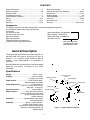
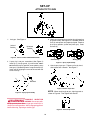
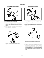
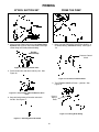
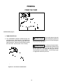
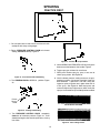
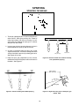
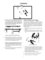
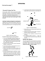
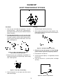
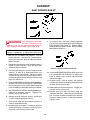
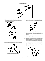
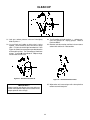
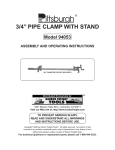
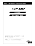
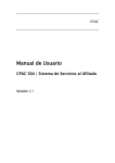
R
505
HIGH PERFORMANCE
AIRLESS SPRAYER
OWNER'S MANUAL
Easy Does It From Set Up to Clean Up
Read Warnings
Assemble Cart
Attach Tip to Gun
Attach Return Hose
Attach Paint Hose
Prepare to Prime
Attach Suction Set
Prime Pump
Set Pressure
Spray
Short Term Storage
OR
Clean Up
Questions? ... Need Help?
Wagner maintains a toll-free help line for you should
you have any comments or problems with this Wagner
product. Call us first ....for answers fast...
Maintenance
PRINTED IN THE U. S. A.
Wagner Technical Service
1-800-328-8251
Hours: Weekdays: 8:00 - 4:30 Central Time
Weekends: 9:00 - 4:00 Central Time
Optional Hopper Accessory
1
Form No. 0270993-11/93
CONTENTS
General Description ....................................................... 2
Safety Precautions ...................................................... 3-6
Extension Cord............................................................... 7
Grounding Instructions ................................................... 7
Pressure Relief Procedure ............................................. 8
Set Up ....................................................................... 9-11
Priming .................................................................... 12-14
Spraying .................................................................. 15-18
Short Term Storage ...................................................... 19
Cleanup and Long Term Shutdown ........................ 20-22
Maintenance ........................................................... 23, 24
Optional Hopper ........................................................... 25
Trouble Shooting .................................................... 26, 27
Parts Lists ............................................................... 28-30
Accessories List ........................................................... 31
Warranty ........................................................ Back Cover
Components:
The shipping carton for your 505 Painting System contains the following components:
Cart frame with wheels, motor and pump attached.
Cart handle
Spare Outlet Spring, P/N 0047485
Pail bracket/cart foot
Spare Tip Seal , P/N 0156713
Suction set and return tube
Return tube fitting , P/N 0088715
Spray gun and filter
Operator’s manual
Spray tip and gasket
Three bolts, washers and wing nuts
ARE LOCATED IN THE
25-foot 3/16-inch higher pressure hose
LITERATURE SET WITH
REGISTRATION CARD
General Description
The Wagner 505 High Performance Airless Sprayer is a
precision power tool used for spraying many types of
materials. It is a relatively simple machine to operate,
however, a basic understanding of its components is
necessary.
Read and follow this instruction manual carefully for proper
operating instructions, maintenance and safety
information.
Specifications
Weight: ................................................... 27 lbs. (12 kg )
Capacity: ............................................... Up to 1/3 gallon
(1-1/4 liters) per minute
Power Source: ............................ 1/3 HP Electric Motor,
totally enclosed, fan cooled.
Power Requirement: ......................... 15 amp minimum
circuit on 115 VAC, 60 HZ current.
Generator – 15 amp A/C.
Spraying Pressure: .............................. Up to 2,500 psi.
Safety Features: .................. Spray gun safety lock and
pressure diffuser; built-in tip safety
guard; priming knob for safe
pressure release.
Portability: ........................ Compact design, light weight
for easy movement.
Capability: ............................ Sprays a variety of paints,
oil base, latex, primers, stains,
preservatives and other nonabrasive
materials, including pesticides and
liquid fertilizers.
Hydraulic Pump
Pressure Control
Knob
Priming Knob
Paint Block
Suction Set
Paint Hose
On/Off Switch
Spray Gun
Figure 1 – Wagner 505 Airless Sprayer
2
SAFETY PRECAUTIONS
This manual contains information which must be read and understood before using the equipment. When you come to an
area which has one of the following symbols, pay particular attention and make certain to heed the safeguard.
WARNING
Important safety information indicates a hazard which may cause serious injury or loss of life.
CAUTION
Important information that tells how to prevent damage to equipment or how to avoid causes of minor injuries.
Notes: Gives important information which should be given special attention.
CAUTION
THIS UNIT IS PROVIDED WITH A THERMALLY PROTECTED AUTOMATIC RESET. IF AN OVERLOAD
OCCURS THE THERMALLY PROTECTED AUTOMATIC RESET DISCONNECTS THE MOTOR FROM THE
POWER SUPPLY.
• Motor will restart without warning when protector automatically resets.
• Always disconnect motor from power supply before working on equipment.
• When thermally protected automatic reset disconnects the motor from the power supply, relieve pressure by
turning priming valve to "prime" A .
• Turn ON-OFF switch OFF.
CAUTION: THE CAUSE OF THE OVERLOAD SHOULD BE CORRECTED BEFORE RESTARTING. (SEE
TROUBLE SHOOTING )
3
WARNING
HAZARD
PREVENTION
Injection Injury - A high pressure stream of paint produced by this equipment can pierce the skin and
underlying tissues, leading to serious injury and possible amputation.
• Maximum operating range of the gun - 2500 PSI fluid
pressure.
• NEVER aim the gun at any part of the body.
• NEVER allow any part of the body to come in contact
with the fluid stream. DO NOT come in contact with a fluid
stream created by a leak in the fluid hose.
• NEVER put hand in front of the gun. Gloves will NOT
provide protection against an injection injury.
• ALWAYS lock the gun trigger,shut fluid pump off and
release all pressure before servicing, cleaning tip guard,
changing tips, or leaving unattended. Simply turning off
the electrical power will not release pressure in the
system. The Prime Spray Valve must be turned to the
prime A position to relieve the pressure.
• ALWAYS have the tip guard in place while spraying. The
tip guard provides some protection against injection
injuries but is mainly a warning device.
• ALWAYS remove spray tip before flushing or cleaning
the system. Refer to Cleaning Instructions.
DO NOT TREAT AS A SIMPLE CUT! Injectioncan lead to amputation. See a physician immediately.
• Paint hose can develop leaks from wear, kinking, abuse
etc. A leak is capable of injecting material into the skin.
The paint hose should be inspected before each use.
NOTE TO PHYSICIAN: Injection into the skin
is a traumatic injury. It is important to treat the
injury surgically as soon as possible. DO
NOT delay treatment to research toxicity.
Toxicity is a concern with some coatings
injected directly into the blood stream. Consultation with a plastic surgeon or reconstructive hand surgeon may be advisable.
• NEVER use a spray gun which does not have a trigger
lock and trigger guard in place and in working order.
• All accessories must be rated at or above 2500 P.S.I.
(Includes spray tips, guns, extensions, and hose).
• In case of skin injection see physician immediately.
4
WARNING
HAZARD
PREVENTION
Explosion or fire - Solvent and paint fumes can explode or
ignite, causing property damage and or severe injury.
• Exhaust and fresh air introduction must be provided to
keep the air within the spray area free from accumulation
of flammable vapors.
• Avoid all ignition sources such as static electricity sparks,
open flames such as pilot lights, hot objects such as
cigarettes, and sparks from connecting and disconnecting power cords and working light switches.
• Fire extinguishing equipment must be present and in
working order.
• Keep the pump away from spray area to avoid solvent
and paint fumes. The pump contains arcing parts which
emit sparks.
• Do not spray paints and other inflammable fluids which
have a flashpoint below 21° C (70° F). (Flashpoint is the
temperature at which a fluid begins giving off a sufficient
amount of flammable vapor that could ignite when exposed to a flame or spark.)
• High velocity flow of material through equipment may
develop static electricity. The equipment being used, and
objects in and around the spray area must be properly
grounded to prevent static discharge and sparks.
• Use only conductive or grounded high pressure fluid
hoses for airless applications. Be sure that gun is grounded
through hose connections.
• Power cord must be connected to a grounded circuit.
(See proper grounding instructions.)
• Follow the material and solvent manufacturer's safety
precautions and warnings.
• WHEN FLUSHING EQUIPMENT use lowest possible
pressure.
5
WARNING
PREVENTION
HAZARD
Explosion hazard incompatible materials - May cause
property damage or severe injury.
• DO NOT USE BLEACH.
• DO NOT use halogenated hydrocarbon solvents.
• Halogenated hydrocarbon solvents such as methylene
chloride and 1,1,1 - Trichlorethane are not compatible
with aluminum and may cause an explosion. If unsure of
a material’s compatibility with aluminum, contact your
coatings supplier.
Hazardous vapors - Paints, solvents, insecticides, and
other materials may be harmful if inhaled causing severe nausea, fainting, or poisoning.
• Use a respirator or mask whenever there is a chance that
vapors may be inhaled. Read all instructions with the
mask to insure that it will provide the necessary protection
against the inhalation of harmful vapors.
General - May cause property damage or severe injury.
• Read all instructions and safety precautions before operating.
• Comply with all appropriate local, state and national
codes governing ventilation, fire prevention, and operation.
• The United States Government Safety Standards have
been adopted under Occupational Safety and Health Act.
These standards, particularly the General Standards,
Part 1910 and construction Standard, Part 1926, should
be consulted.
• This high pressure airless pump is designed to be used
with authorized parts only. When using this pump with
parts that do not comply with the minimum specifications
and safety devices of the pump manufacturer, the user
assumes all risks and liabilities.
• Before each use, check all hoses for cuts, leaks, abrasion
or bulging of cover or damage or movement of couplings.
If any of these conditions exist, replace the hose immediately. Never repair a paint hose. Replace it with another
grounded hose.
• All hoses, swivels, guns, and accessories used with this
unit must be pressure rated at or above 2500 PSI.
• DO NOT spray on windy days.
6
Extension Cord
This product is for use on a nominal 120 volt circuit, and has
a grounding plug that looks like plug illustrated in Figure 2
(A) below. A temporary adapter which looks like the adapter
illustrated in Figure 2 (B) and (C), may be used to connect
this plug to a 2 pole receptacle as shown in Figure 2 (B) if
a properly grounded outlet is not available. The temporary
adapter should be used only until a properly grounded
outlet as shown in Figure 2 (A) can be installed by a
qualified electrician. The green colored rigid ear lug, or the
like extending from the adapter must be connected to a
permanent ground such as a properly grounded outlet box
cover. Whenever the adapter is used, it must be held in
place by a metal screw.
Use only a 3-wire extension cord that has a 3-blade
grounding plug and a 3-slot receptacle that will accept the
plug on the product. Make sure your extension cord is in
good condition. When using an extension cord, be sure to
use one heavy enough to carry the current your product will
draw. An undersized cord will cause a drop in line voltage
resulting in loss of power and overheating. A 14 or 12
gauge cord is recommended.
NOTE: More than 100 feet of extension cord is not
recommended. Use more paint hose, not more
extension cord. Shorter extension cords will assure
maximum electrical power for proper operation.
Grounded
Outlet
Grounding Instructions
This product must be grounded. In the event of an electrical
short circuit, grounding reduces the risk of electric shock by
providing an escape wire for the electric current. This
product is equipped with a cord having a grounding wire
with an appropriate grounding plug. The plug must be
plugged into an outlet that is properly installed and grounded
in accordance with all local codes and ordinances.
WARNING
Grounding Pin
(A)
Cover of Grounded Outlet Box
Adapter
Metal
Screw
Improper installation of the
grounding plug can result in a
risk of electric shock.
(C)
If repair or replacement of the cord or plug is necessary, do
not connect the green grounding wire to either flat blade
terminal. The wire with insulation having an outer surface
that is green with or without yellow stripes is the grounding
wire and must be connected to grounding pin.
(B)
Tab for
Grounding Screw
Figure 2 – Grounding Methods
Check with a qualified electrician or serviceman if the
grounding instructions are not completely understood, or if
in doubt as to whether the product is properly grounded. Do
not modify the plug provided; if it will not fit the outlet, have
the proper outlet installed by a qualified electrician.
7
Pressure Relief Procedure
Follow this procedure after the unit is assembled and before any operation which involves the spray gun such as
changing tips or accessories, or cleaning and maintenance.
3. Trigger gun to remove any pressure which may still be
in the hose.
1. Make sure PRESSURE CONTROL KNOB is at its lowest
setting (counterclockwise).
Pressure Control
Knob
2. Turn PRIMING KNOB to PRIME A position.
4. Lock gun trigger in the Off position.
Prime A
Spray B
Knob
Trigger Lock
Injection hazard possible. Do
WARNING not spray without tip guard in
place. NEVER trigger gun unless tip is completely turned
to the spray or unclog position. ALWAYS engage trigger
lock before removing, replacing or cleaning tip.
8
SET-UP
ASSEMBLE CART
Tools needed:
Some assembly is required to get your Wagner 505
Airless Sprayer ready to go. You will need two adjustable
wrenches, a screw driver and a pair of pliers.
Pail Bracket
NOTE: Sprayer should remain unplugged during
assembly.
1. Slide pail bracket (1) onto cart frame and attach with
one bolt, washer and wing nut (2). See Figure 2 and
Figure 3 A. This bracket helps to keep the sprayer
stable in addition to providing a rest for the paint
bucket and a catch for the bucket handle.
Bolt, washer
and wing nut
Figure 3A - Attaching Pail Bracket
4
2. Attach cart handle (3). Face the hose hook toward the
front of the unit. Use two bolts, washers and wing nuts
(4), tightening securely. See Figure 3B.
3
Cart Handle
Bolt, washer
and wing nut
2
1
Figure 2 – Cart Assembly Diagram
Figure 3B - Attaching Cart Handle
9
SET-UP
ATTACH TIP TO GUN
3. Check seal alignment by removing tip and inspecting
tip guard visually, See Figure 6. If needed, remove
seal (3) and replace until properly aligned. Replace
tip to spray position, (arrow away from gun). Insert
red seal (4).
1. Lock gun. See Figure 4.
Locked
Position
Unlocked
Position
Figure 4 - Gun in Locked & Unlocked Position
Correct Way
2. If spray tip is not pre- assembled, (See Figure 5)
insert tip (1) into tip guard, (2) and turn 90° counterclockwise to spray position (arrow pointing away
from gun). Cylinder of tip forms a stop for the seal (3).
Insert seal (3) aligning the curve of the seal with the
curve of the tip.
3
Wrong Way
Figure 6 - Spray Tip Assembly
4. Attach spray tip to gun. Tighten nut first by hand,
then tighten with a wrench. See Figure 7.
4
2
Red Seal
1
Figure 7- Attach Tip to Gun
NOTE: When attaching tip to gun, align tip guard as
Figure 5 – Spray Tip Assembly
shown in Figure 8. Then tighten with wrench.
INJECTION
WARNING POSSIBLE
HAZARD. Do not spray without tip guard in place. Never trigger gun unless tip is in
the spray or unclog position. Always engage trigger lock
before removing, replacing or cleaning tip.
Figure 8 - Vertical Tip Pattern
10
SET-UP
ATTACH RETURN HOSE
ATTACH PAINT HOSE
1. Be sure motor switch is turned OFF.
2. Screw brass fitting of return tube into upper port on
side of pump. (The brass fitting is located in the
literature set.) Tighten firmly by hand. See figure
above.
1. Attach high pressure hose to hose port, using an
adjustable wrench to tighten firmly. (See illustration
above.)
2. Attach gun to other end of high pressure hose.
Tighten securely with two adjustable wrenches. See
Figure 10.
3. Press return tube (small tube) to brass fitting and
fasten with clamp. See Figure 9.
Figure 10 - Attaching High Pressure Hose to Gun.
Figure 9 - Fastening Return Tube with Clamp
3. Plug unit into a properly grounded outlet or heavy
duty grounded extension cord. Do not use more
than 100 feet of cord. If you must spray a long
distance from a power source, use more paint hose,
not more extension cords. Use a minimum size of 16
gauge electric cord for 50 feet; 12-14 gauge for 100
feet.
11
PRIMING
PREPARE TO PRIME
4. Force the inlet valve to open and close by pushing on
it with the eraser end of a pencil or screwdriver, it
should move up and down about 1/16 inch. Continue
until water or oil is sucked into unit. This will assist in
wetting the moving parts and breaking loose any old
paint residue. See Figure 13.
1. Lay unit back on its handle so inlet valve is facing up.
Fill inlet valve with water or light household oil.
2. Make sure Prime/Spray Knob is in Prime A position
and Pressure Knob is turned to the lowest pressure.
(Counter clockwise) See Figure 11. Turn unit on.
Inlet Valve Facing Up
PrimeA /Spray B
Knob
Hose Port
Figure 13 - Opening Inlet Valve
5. Put palm of hand over inlet valve and feel for a slight
suction while increasing the pressure control to the
maximum setting. See Figure 14. If suction is felt go
to step 6. If no suction is felt see Cleaning and
Servicing Outlet Valve. ( Repeat steps 1 through 5 if
necessary.)
Figure 11 - Prime/Spray Knob
3. Increase pressure half turn.
Pressure Control
Knob
Figure 14 - Checking for Suction
Figure 12 - Pressure Control Knob
6. Turn Pressure Control Knob to minimum pressure
and shut off unit.
7. Return unit to upright position.
12
PRIMING
PRIME THE PUMP
ATTACH SUCTION SET
1. Attach Suction Tube to inlet valve and tighten firmly
by hand. See Figure 15. Be sure threads are straight
so the fitting turns freely without binding.
1. Make sure the PRESSURE CONTROL KNOB is at
its lowest setting (counterclockwise). See Figure
18.
(Do Not
cross thread)
Pressure Control
Knob
Figure 15 - Attaching Suction Tube
2. Place suction tube and return tube in paint. See
Figure 16.
Figure 18 - Set Pressure Control Knob
2. Turn PRIMING KNOB to Prime A position. See
Figure 19.
Figure 16 - Place Suction Tube and Return Tube in
Paint.
Prime A
Spray B
Knob
3. Set paint bucket onto pail bracket and attach
handle. See Figure 17.
Figure 19 - Priming Knob Setting
Figure 17 - Attaching Paint Pail Handle
13
13
PRIMING
PRIME THE PUMP
Continued from page 13
3. TURN SPRAYER ON.
Always reduce pressure to zero
before changing the position of
the priming knob. Failure to do so may cause damage to
the paint pump diaphragm.
CAUTION
4. Turn PRESSURE CONTROL KNOB between half
and full pressure. See Figure 20. You should then
be able to see the paint move through the suction
tube to the pump. Continue until paint flows through
the return tube. (Let unit prime 1 to 2 minutes).
If the Pressure Control Knob is
reduced to zero and the Priming
Knob is still on spray during sprayer operation, there will
be high pressure in the hose and spray gun until the
Priming Knob is turned to PRIME A or until the spray gun
is triggered to relieve the pressure.
CAUTION
Figure 20 - Turn Pressure Control Knob
14
SPRAYING
PRACTICE FIRST
1. Be sure paint hose is free of kinks and clear of traffic
or objects with sharp cutting edges.
2. Return PRESSURE CONTROL KNOB to its lowest
setting (counterclockwise). Figure 21.
Figure 23 - Practice on scrap material.
5. Unlock SPRAY GUN TRIGGER LOCK by turning lock
down toward the bottom of the handle. Figure 4
6. Trigger spray gun to bleed air out of hose.
7. When paint reaches spray tip, spray a test area to
check spray pattern. See Figure 23.
Figure 21 - Pressure Control Knob Setting
3. Turn PRIMING KNOB to SPRAY B position. Figure
22.
8. Use the lowest pressure setting necessary to get a
good spray pattern. If pressure is too high, material is
over-atomized. If pressure is too low, tailing will
appear or paint will spatter out in gobs rather than in
a fine spray. See Figure 24. Most latex paints and
stains will require very high pressure, which is why the
sprayer is built to deliver up to 2,500 psi when needed.
PrimeA
Spray B
Knob
GOOD SPRAY PATTERN
Figure 22 - Priming Knob Setting
4. Turn PRESSURE CONTROL KNOB completely
clockwise to maximum pressure, Figure 21. Paint
should then begin to flow into the paint hose, causing
it to stiffen.
Figure 24 - Paint Tailing Pattern
15
SPRAYING
SPRAYING TECHNIQUE
1. The key to a good paint job is an even coating over the
entire surface. With spray painting, this is done by
using even strokes, with your arm moving at a constant speed and keeping the spray gun a constant
distance from the surface.
Even Coat on Work Throughout
Approximately
Approximatley
10toto12
12Inches
Inches
10
2. In most cases, the best spraying distance is 10 to 12
inches between the spray tip and the surface.
3. As much as possible, keep the spray gun at right
angles to the surface. This means moving your entire
arm back and forth rather than just flexing your wrist.
See Figures 25 and 26.
Right
Way To Spray
Steady Arm
Figure 26 - Result of smooth arm stroke and steady,
even speed while spraying.
4. Keep the spray gun perpendicular to the surface,
otherwise one end of the pattern will be thicker than
the other. See Figure 27.
Approximately
10 to 12 Inches
Right Way
Wrong Way
Figure 25 - Result of Flexing Wrist While Spraying
Figure 27 - Right and wrong ways to hold spray gun
toward work.
16
SPRAYING
5. The spray gun should be triggered off at the end of
each stroke and on again at the beginning of the next.
This avoids paint buildup at the end of the stroke
which may result in runs and sags. Triggering at the
end of the stroke also saves paint and results in a
better looking job. See Figure 28.
Approximately
Approximatley
10
10 to
to 12
12 Inches
Inches
If Spray Tip Becomes Clogged
The spray gun is equipped with a reversible tip which
enables you to quickly and effectively blow out any particles
of old paint or other contaminants that may obstruct the
paint flow through the tip. If the spray pattern becomes
distorted or stops completely while the gun is triggered on,
follow these steps.
Work
1. Release the trigger and put on the safety lock. See
Figure 4.
Even Steady
Stroke
Start
Stroke
Pull
Trigger
2. Rotate the reversible tip cylinder arrow 180° so the
point of the arrow is toward the rear of the gun. Figure
29.
End
Stroke
Release
Trigger
Figure 28 - Proper Way to Trigger Spray Gun
6. Overlap each stroke by about 30%. This will assure
a paint coating that is uniform across the work. One
way to do this is to point the spray tip at the edge of
the last stroke before triggering the gun on.
7. When taking a short break from painting (up to 1 hr.),
lock the spray gun trigger OFF, reduce pressure to its
minimum (zero) setting and set the unit to prime A .
Turn sprayer off and unplug. Refer to Pressure
Relief Procedure.
Figure 29 - Reverse Tip
3. Unlock the trigger and squeeze it open, pointing the
gun at a scrap piece of wood or cardboard. This allows
pressure in the paint hose to blow out the obstruction.
When the nozzle is clean, paint will come out in a
straight, high pressure stream.
8. If you expect to be gone more than 1 hour follow the
short term clean up procedure.
4. Release the trigger and re-lock it. Figure 4
5. Reverse the tip so the arrow points forward again.
6. Unlock the trigger and resume spraying.
17
SPRAYING
Continued from page 17
6. Insert the top of the filter (Figure 30) into the gun body
fitting under the tip of the spray gun. See Figure 31.
Cleaning The Spray Gun Filter
The spray gun includes a filter to catch particles before
they reach the spray tip. If this filter becomes clogged or
obstructed it will reduce the flow of paint, changing the
spray pattern and possibly damaging the filter.
This filter must be cleaned at least daily and perhaps
even every four hours with certain types of latex
materials.
Spring
If the filter is not cleaned at the proper time, it will plug from
the top down. When there is about 1 inch of filter that isn't
plugged, the heavy flow of paint will blow pin holes in the
filter. See Figure 30. This in turn will allow unwanted
particles to get into the spray tip, causing spray tip to clog.
Gun Body Fitting
Filter
Top of Filter
Sealing Washer
Filter Housing
Figure 31 - Gun Filter Cleaning.
7. Replace the spring and sealing washer into the base
of the filter housing.
8. Slide the filter housing over the filter and tighten it
securely to the gun, using a wrench.
Pin Hole
9. Reattach the hose, tightening it securely with two
wrenches.
Figure 30 - Gun Filter Cleaning.
10. Turn PRIMING KNOB to SPRAY B , (Figure 10)
increase pressure to its previous setting and resume
spraying.
To clean the filter during the painting process:
1. Turn spray PRESSURE CONTROL KNOB to minimum setting and turn PRIMING KNOB to PRIME A .
This will bleed off the pressure in the paint hose and
filter. Trigger gun to be sure pressure is gone. Refer
to Pressure Relief Procedure.
Suction Set Screen
The screen at the bottom of the suction set may also need
cleaning periodically. Check it every time you change
paint buckets. Remove screen by pulling it out of the
retainer with a pliers. Clean the screen with water or
solvent and a soft-bristle brush, if needed.
2. Remove spray gun from hose using two adjustable
wrenches. See Figure 10
3. Unscrew filter housing, using adjustable wrench on
the nut at the bottom of the housing.
4. Remove filter being sure not to lose the spring and
sealing washer which is located in the bottom of the
filter housing.
5. Clean filter thoroughly (or put in a new filter). To clean
the filter, swish it in water or the type of solvent
appropriate to the paint you are using. If this isn’t
sufficient, use a natural or nylon bristle brush dipped
in the appropriate solvent or water. Do not use a wire
brush or any sharp instrument.
Figure 32 - Remove And Clean Screen
18
CLEAN UP
SHORT-TERM/OVERNIGHT STORAGE
Shut-down
Start-up
1. Lock the gun and reduce the pressure. Turn the
sprayer to prime A and shut it off. Unplug sprayer.
Leave the suction set in the paint. Refer to Pressure
Relief Procedure.
1. Remove the gun from the plastic bag.
2. Stir the water into the paint for latex materials. Remove the seal from the paint bucket and stir the paint
for all other materials.
2. For latex materials only, pour 1/2 cup water slowly
on the top of the paint to prevent the paint from drying.
For other materials, seal the paint container with a
piece of plastic while the suction tube is still in the
paint. See Figure 33.
– OR –
Figure 35 - Stir Material Before Spraying
3. Check to be sure the sprayer is in the Prime A
position with the pressure completely reduced.
Figure 33 – Add 1/2 Cup Water to Latex Paint
Seal Container for Other Materials.
4. Plug sprayer in and turn on.
3. Wrap the spray gun (completely assembled) in a
damp cloth and place it in a plastic bag. Seal the bag
shut. See Figure 34.
5. Turn the sprayer to Spray B and gradually increase
the pressure.
6. Test the sprayer on a practice piece and begin
spraying.
Figure 34 - Place Gun in Sealed Bag
4. Place the sprayer in a safe place out of the sun for
short-term storage.
Figure 36 - Test on scrap material.
19
CLEANUP
SHUT DOWN/CLEAN UP
9. To save paint left in the hose, carefully trigger the
gun (with spray tip removed) against the inside of the
paint container. See Figure 37. Reduce PRESSURE CONTROL KNOB to zero, then turn PRIMING KNOB to SPRAY B .
Do not allow paint to build up on
Overheating of the
motor will result. Do not allow flammable solvents to
come in contact with the motor, which could ignite.
WARNING the motor.
NOTE: You will need an extra bucket with cleaning
solution, a toothbrush, an adjustable wrench and
rags.
1. Lock the gun and reduce the pressure. Turn the
sprayer to prime A and shut it off. Unplug sprayer.
Leave the suction set in the paint. Refer to Pressure
Relief Procedure.
2. Remove suction tube from paint and hold it above a
bucket of water or solvent. Leave the return tube
aimed into the paint bucket.
Figure 37 - Save Paint Back To Paint Can.
3. If spraying with latex paint, use warm soapy water for
cleaning. If using oil or alkyd-based paints, use
mineral spirits or paint thinner. Do not use these
solvents on latex paint, or the mixture will turn into a
jelly-like substance which is difficult to remove. Plug
the unit in and turn on.
10. Increase PRESSURE CONTROL KNOB again until
paint starts to flow into the bucket. As soon as the
water or solvent starts to come into the bucket,
release the trigger.
11. Change to clean water or solvent and continue
circulating for another 5 minutes to thoroughly clean
the hose, pump and spray gun.
4. Increase PRESSURE CONTROL KNOB clockwise
to about 1/3 to 1/2 maximum pressure. This will draw
the remaining paint in the suction tube through the
pump and down the return tube into the paint bucket.
12. Reduce pressure and turn to prime A . Trigger gun.
Lock gun and shut sprayer off.
5. Set PRESSURE CONTROL KNOB counterclockwise back to minimum pressure. Trigger gun to
relieve pressure and lock gun.
13. Remove spray gun from paint hose, using two
adjustable wrenches. Remove filter housing from
gun. Place gun and filter assembly into a container
of water or solvent to soak. Cover paint container
and set it aside.
6. Remove spray tip and guard, washer, and let soak
in warm water or appropriate solvent.
7. Place suction tube and return tube in container of
water or compatible solvent.
8. Increase pressure to about 1/2 maximum pressure
and let circulate for 2-3 minutes to flush paint out of
the pump, suction tube and return tube.
20
CLEAN UP
14. Clean spray tip and gun filter with a soft brush.
Reassemble spray tip in cleaning position. (Arrow
points to back of the gun.)
16. Turn the unit on and unlock gun trigger. Turn to
Spray B and point gun to side of cleaning bucket.
Figure 41 - Cleaning Bucket
17. Trigger gun and gradually turn pressure knob clockwise to 1/2 pressure. Continue for approximately 30
seconds.
18. Release and lock trigger, reduce pressure, turn to
prime A . Turn unit off.
19. Remove tip assembly. Raise the suction set above
the cleaning solution. Turn unit on, turn to spray B
increase pressure and allow suction tube to run dry.
15. Attach paint hose to gun,tighten with two wrenches.
20. Remove large suction tube from inlet valve, See
Figure 42 and point gun into cleaning bucket, See
Figure 41. Reduce pressure about 1/2, unlock gun,
trigger gun until hose is pumped dry.
Figure 40 - Attach Paint Hose to Gun
Figure 42 - Removing Large Suction Tube
21
CLEAN UP
23. Turn Prime/Spray Knob to prime A , reduce pressure, shut sprayer off. Unplug sprayer. Refer to
Pressure Relief.
24. Remove and clean suction set filter in clean water or
solvent with soft brush. Reassemble.
21. Lock gun, reduce pressure and turn Prime/Spray
Knob to prime A .
22. Lay unit back on handle so inlet valve is facing
upward. Clean threads of inlet valve with a damp
cloth. Fill inlet valve with light household oil. See
Figure 43. Slowly increase pressure to distribute the
oil through the pump. Turn Prime/Spray Knob from
prime A to spray B to distribute oil. Replace large
suction tube to inlet valve.
Figure 43 - Fill Inlet Valve With Oil
Figure 44 - Remove And Clean Filter
25. Wipe entire unit, hose and gun with a damp cloth to
remove accumulated paint.
IMPORTANT!
Proper cleaning and oiling of the pump after use
are the most important steps you can take to insure
proper operation after storage.
22
MAINTENANCE
CLEANING VALVES
Follow these procedures when encountering problems indicated in the trouble shooting section.
NOTE: The inlet valve must be oiled after every job.
This will reduce or eliminate priming problems the next
time the sprayer is used. See Figure 43.
Removing and Cleaning Inlet Valve
4. Thoroughly clean the valve assembly with solvent
and brush.
1. Be sure sprayer is off.
5. A properly seated valve filled with water and held
vertically will not drip out the bottom of the valve. If
you have properly cleaned the valve and water drips
out the bottom, the valve is worn and needs to be
replaced.
2. Using a 27 millimeter socket or box end wrench,
remove the inlet valve assembly.
Remove
Inlet Valve
6. Install cleaned or new valve in the pump block and
then fill the valve with light oil or solvent.
7. If none of the above steps work, see Troubleshooting.
Cleaning and Servicing Outlet Valve
Figure 45- Removing Inlet Valve
3. Test movement of the valve by pushing on it from the
open end of the valve housing with the eraser end of
a pencil or a screwdriver. It should move about 1/16
inch. If it doesn't move, it is probably full of dry paint
or other debris and should be cleaned or replaced.
It may be occasionally necessary to remove and clean the
outlet valve or replace normal wear parts inside the valve.
See Figures 47 and Figure 48.
1.
Remove outlet cap with adjustable wrench.
Outlet Valve
Figure 47 - Removing Outlet Valve
Figure 46 - Test Movement of Valve
23
MAINTENANCE
CLEANING VALVES
2. If possible, leave the copper washer under the cap in
place. At least be sure to replace it with the same
side up. (The top will show the imprint of the end cap,
while the bottom should be perfectly flat to match
seat in the pump casting.) See Paint Pump Assembly Parts Diagram,Item 4 for replacement part number.
A spare outlet
valve spring is included in the litSpring
erature set.
Cap
Ball
Seat
Seal
3. With a wire hook or tweezers, remove the small
spring inside the valve. Replace if broken, or worn or
clean as necessary. See Paint Pump Assembly
Parts Diagram, Item 4 for replacement part number.
This spring is manufactured to a very specific tension, so do not put in an unauthorized subsitute.
Proper spring length is 7-1/2 coils.
4. Using a six-millimeter allen wrench, remove the seat
and ball assembly. See Figure 48.
5. Clean parts thoroughly. If the ball or seat show any
sign of wear or damage, replace it with a new one.
This carbide ball must seal tightly against its seat for
the valve to function properly.
Figure 48 - Servicing Outlet Valve
NOTE: Wear on the ball is almost impossible to
detect visually. A sure way to test for a worn outlet
valve assembly is to run the sprayer with water only
for 10 to 15 minutes on high pressure in the spray
setting without triggering the gun.
6. When reassembling, first cover all parts with a thin
coat of light oil. Tighten the valve seat securely with
the 6-millimeter hexagonal wrench, then drop in the
valve ball. Re-insert the spring and replace the cap,
being sure the copper washer is in place and the
tongue on the cap fits inside the spring. Tighten the
cap securely with an adjustable wrench. Do not
over-tighten.
If the valve is defective, the end cap will get very hot
to the touch. If it is functioning properly, it will stay
approximately the same temperature as the water
running through it.
Priming Knob Slippage
Sometimes the two allen screws holding the black
plastic PRIMING KNOB outer cover will vibrate loose.
This allows the knob to turn without changing the valve
setting. If this happens, loosen the screw with a 1/16
allen wrench, turn the knob to spray and retighten.
24
OPTIONAL HOPPER ASSEMBLY
CONVERTING SPRAYER FOR HOPPER OPERATION
The hopper assembly consists of the hopper, hopper
return tube and hopper screen. To make the conversion:
1. Remove suction tube and return tube and brass
return tube fitting from the unit.
2. To convert the cart into its horizontal configuration
as shown in Figure 49, reverse the positions of the
handle and pail bracket.
3. Screw the hopper directly onto the inlet valve where
the suction tube was removed. Make the connection
hand tight, just tight enough to prevent paint leakage
or air suction around the threads.
4. Screw in the plastic return tube fitting into the paint
pump port that the brass fitting was removed from.
Attach hopper return tube to the fitting where the
suction set return tube was removed. The connection needs to be only hand tight.
5. Fit the hopper screen into the bottom of the hopper,
being sure it is properly seated.
NOTE: The hopper screen is essential to trap
debris and other foreign objects from entering
the pump. Do not operate the sprayer without
the screen properly in place.
Hopper Return Tube
Cleaning Hopper Unit
To clean the hopper unit:
Hopper
1. Flush the pump and hose with water or solvent
following the same procedure as with the suction
tube, being sure the return tube is thoroughly flushed
out.
2. Clean the hopper screen with water or appropriate
solvent. If necessary use a nylon or natural bristle
brush dipped in solvent or soapy water.
3. Wash the hopper thoroughly using soapy water
for latex paint, the appropriate solvent with other
materials.
Figure 49 - Optional Hopper
25
TROUBLE SHOOTING
Problem
Cause
Remedy
Sprayer does not start up.
Sprayer not plugged in.
ON/OFF switch OFF.
Blown fuse in circuit.
No voltage or low voltage
at wall plug.
Unit turned off under pressure.
Damaged motor cord or
extension cord, or capacity too low.
Thermal overload tripped
Motor problem.
Plug in.
Flip switch to ON.
Replace fuse.
Test power supply voltage.
Sprayer starts up but does not
draw in paint. (Make sure prime/
spray knob is in prime position.)
Unit will not prime or has lost
prime.
No paint. Suction tube not
totally immersed in paint.
Suction set filter clogged.
Hopper screen clogged
Suction tube loose at inlet valve.
Inlet valve stuck.
Outlet valve stuck.
Prime spray valve plugged
or dirty.
Inlet valve worn or damaged.
Diaphragm problem.
Hydraulic oil level low or empty.
Sprayer draws up paint but
drops away when gun is
opened.
Turn Prime/Spray Knob to Prime position.
Replace extension cord.
Allow motor to cool,move to a shady spot.
Take to Wagner Authorized Service Center.
Reprime Unit.
Immerse suction tube in paint.
Clean filter.
Clean screen.
Clean connection and tighten.
Clean inlet valve.
Clean outlet valve.
Replace any worn parts.
Take to Wagner Authorized Service Center.
Clean or replace.
Take to Wagner Authorized Service Center.
Take to Wagner Authorized Service Center.
Worn spray tip
Suction set filter clogged.
Optional hopper screen clogged.
Gun or spray tip filter plugged.
Replace with new tip.
Clean filter.
Clean screen.
Clean or replace filter. Keep extra filters
on hand.
Paint too heavy or coarse.
Thin or strain paint.
Dirty or worn outlet valve assembly. Clean or replace.
Inlet valve worn or damaged.
Replace valve.
NOTE: The electric motor should always be kept clean
and dry. Paint acts as an insulator, therefore too much
paint on the motor will cause the motor to overheat.
NOTE: When priming valve is on Spray B and there
is flow through the return tube, remove the priming
valve and clean or replace.
26
TROUBLE SHOOTING
Problem
Cause
Remedy
Spray gun won't shut off.
Worn ball or seat.
Foreign matter or paint
buildup or dried paint between
ball and seat. (Caused by
improper cleaning of gun.
Take to Authorized Wagner Service Center.
Take to Authorized Wagner Service Center.
Spray gun leaks.
Worn or dirty internal parts.
(Caused by improper cleaning
of gun.)
Take to Authorized Wagner Service Center.
Tip assembly leaks
Assembled incorrectly.
Worn seal.
Check assembly.
Replace seal.
Spray gun won't spray.
Spray tip, gun filter or tip
filter plugged.
Clean spray tip.
Clean or replace gun filter.
Clean or replace tip filter.
Put tip in Spray position.
Spray tip in Clean position.
Paint tailing.
Thermal overload tripped
WARNING
Pressure is set too low.
Increase pressure.
Gun, tip,or suction filter plugged. Clean filters
Suction tube loose at
Tighten suction tube fitting.
inlet valve.
Tip worn.
Paint too thick
Replace tip.
Thin paint
Motor over heated.
Extension cord too long or
too small gauge.
Paint build up on motor.
Restart under pressure .
Unit sitting in hot sun.
Allow to cool 15 to 30 min.
Allow to cool, replace cord with one shorter or
larger gauge.
Clean paint from motor.
Restart in Prime mode.
Move to a shady location.
Follow Pressure Relief
Procedure before performing any of these
operations since the
motor will restart without warning when the
motor cools sufficiently
27
1
2
9
3
11
4
10
5
Serial Number
Location
6
9
7
8
3
4
Parts Diagram – Final Assembly
ITEM PART NO.
1
2
3
4
5
6
0288478
0270357
9821503
9810111
0270356
0270359
DESCRIPTION
Grip, Handle
Handle, Cart
Washer, Lock
Nut, Wing
Cart Assembly
Wheel
QTY.
1
1
4
2
1
2
ITEM PART NO.
DESCRIPTION
7
8
9
10
0275728
0270358
9800117
-----------
11
0288186
Cap, Hub
Bracket, Pail
Bolt, 1/4-20 x 1-1/2
Paint Pump Assembly
(See Parts Diagram, Page 29)
Housing, Hydraulic
28
QTY.
2
1
3
1
1
1
2
3
4
5
12
6
7
Never remove these
four bolts! Take to
an Authorized Wagner Service Center.
CAUTION
3
11
8
10
9
Parts Diagram – Paint Pump Assembly
ITEM PART NO. DESCRIPTION
1
0281113
2
3
4
5
6
0089564
9970103
0047485
0093635
0090348
Valve, Inlet Assembly
(includes item 12)
Cap, Outlet Assembly
Washer, Sealing, Copper
Spring, Outlet
Ball, 6mm, Carbide
Seat, Ball, Outlet Assembly
QTY.
ITEM PART NO. DESCRIPTION
1
7
8
9
10
11
12
1
2
1
1
1
29
QTY.
0089494
0288379
0088715
0288748
0090533
0089482
Seal, Outlet
Fitting, Outlet
Fitting, Return Tube
Knob Only
Paint Pump with Valve
Washer, Sealing, Nylon
1
1
1
1
1
1
0288172
Repair Kit
Replaces both Holder & Seat
1
2
11
3
10
12
9
4
5
6
1
5
7
8
Parts Diagram – Suction Set Assembly
0270174
ITEM PART NO. DESCRIPTION
1
0270133
2
3
4
5
6
0090622
0281314
0088931
0089882
0270360
Suction Tube Complete
(Includes Items 2 thru 10)
Nut, Suction
Elbow, Adapter, 3/4" x 1"
Ring, Snap
Clamp
Hose, Suction
QTY.
1
1
1
1
2
1
ITEM PART NO. DESCRIPTION
7
8
9
10
11
12
30
0270371
0270369
0090621
0088715
0089096
0270363
Housing, Filter
Filter
Washer
Fitting, Return Hose
Clamp
Tubing, Return
QTY.
1
1
1
1
1
1
1
2
7
3
5
4
6
Parts Diagram – Optional Hopper Assembly
ITEM
PART NO. DESCRIPTION
1
0288144
2
3
0090283
0089917
0088871
QTY.
Hopper, Complete
(lncludes ltems 2 thru 7)
Hopper
Filter Screen, Fine (Shown)
Filter Screen, Coarse
ITEM
PART NO. DESCRIPTION
1
4
0090560
1
1
5
6
7
0093865
0090617
0288668
Return Tube Assembly
(lncludes ltems 5 & 6)
Return Tube
Fitting
Cover, Hopper
Accessories
Part
Number
Description
Part
Number
Description
0153000
0153001
0093896
0149018
0149017
0089731
0154675
0093820
Hose, 25' x 3/16", Grounded
Hose, 50' x 3/16', Grounded
Hose Connector
G-09 Spray Gun
G-10 Spray Gun
Gun Filter Assembly
Gun Filters, Medium/Fine
Adjustable Tip
0154681
0154682
0154683
0154693
0155206
0155208
0088009
0088010
Reversible Tip (light), Stains
Reversible Tip (Medium), Enamel
Reversible Tip (Heavy), Latex
Reversible Tip Repair Kit
Roller Cover, 9" x 3/8" Nap
Roller Cover, 9" x 3/4" Nap
Hydraulic Oil (quart)
Hydraulic Oil (gallon)
31
QTY.
1
1
1
1
Parts and Accessories
1
10
9
3
4
8
7
2
6
5
PARTS LIST
Item Part No.
1
2
0293004
0089731
3
4
5
6
0043590
0089694
0089692
0089959
Description
G-06 Gun Assembly
Filter Assembly
(Includes Items 3,4,5,6)
Spring
Seal, Nylon
Housing Filter
Filter
Item Part No.
7
8
9
10
0293303
0154782
0154783
0154784
0154680
0154693
Description
Guide, Hose
Tip, .011 (Oil based materials)
Tip, .013 (Oil based , latex paints
and stains)
Tip, .015 ( Extra thick materials)
Tip, Body
Seal Kit
Part Numbers may change without notice due to improvements and modifications.
32
LIMITED WARRANTY
AIRLESS PAINT SPRAY EQUIPMENT
This product, manufactured by Wagner Spray Tech Corporation (Wagner), is warranted to the original retail purchaser
against defects in material and workmanship for 30 days from date of purchase for professional/rental use if operated
in accordance with Wagner's printed recommendations and instructions. This warranty applies for one year from date
of purchase for home use.
This warranty does not cover damage resulting from improper use, accidents, user's negligence or normal wear. This
warranty does not cover any defects or damages caused by service or repair performed by anyone other than a Wagner
Authorized Service Center. This warranty does not apply to accessories.
ANY IMPLIED WARRANTY OF MERCHANTABILITY OR FITNESS FOR A PARTICULAR PURPOSE IS LIMITED
TO 30 DAYS FOR PROFESSIONAL/RENTAL USE AND ONE YEAR FOR HOME USE FROM DATE OF
PURCHASE.
WAGNER SHALL NOT IN ANY EVENT BE LIABLE FOR ANY INCIDENTAL OR CONSEQUENTIAL DAMAGES
OF ANY KIND, WHETHER FROM BREACH OF THIS WARRANTY OR ANY OTHER REASON.
If any product is defective in material and/or workmanship during the applicable warranty period, return it with proof
of purchase, transportation prepaid to any Wagner Authorized Service Center. (Service Center listing is enclosed with
this product.) Wagner’s Authorized Service Center will either repair or replace the product (at Wagner’s option) and
return it to you, postage prepaid.
SOME STATES DO NOT ALLOW LIMITATIONS ON HOW LONG AN IMPLIED WARRANTY LASTS OR THE
EXCLUSION OF INCIDENTAL OR CONSEQUENTIAL DAMAGES, SO THE ABOVE LIMITATION AND EXCLUSION
MAY NOT APPLY TO YOU.
THIS WARRANTY GIVES YOU SPECIFIC LEGAL RIGHTS, AND YOU MAY ALSO HAVE OTHER RIGHTS WHICH
VARY FROM STATE TO STATE.
Copyright© Wagner Spray Tech Corporation,1993. All
rights reserved, included right of reproduction in whole or
in part, in any form. Printed in U.S.A.
R
Wagner Spray Tech Corporation
1770 Fernbrook Lane
Minneapolis, Minnesota 55447
Telephone (612) 553-7000
33