1
Diaphragm
Diaphragm Pumps
Pumps
1150
1150
Piston
Piston Pumps
Pumps
EP2105
EP2105
EP2205
EP2205
EP2300
EP2300
EP2300se
EP2300se
EP2400
EP2400
EP2510
EP2510
GP2605
GP2605
GP2905
GP2905
HVLP
HVLP
CS5100
CS5100
CS8100
CS8100
CS9100
CS9100
Maxum
Maxum IIII Gun
Gun
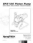
EP2300
Piston Pump
Owner's Manual
Model Numbers:
0294006 Cart Mount
0294036 Low Boy
SprayTECH
1770 Fernbrook Lane
Minneapolis, MN 55447
1297 © 1997 Wagner Spray Tech. All rights reserved. Form No. 0294724E
1
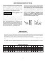
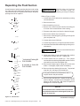
GROUNDING INSTRUCTIONS
This product must be grounded. In the event of an electrical
short circuit, grounding reduces the risk of electric shock by
providing an escape wire for the electric current. This
product is equipped with a cord having a grounding wire
with an appropriate grounding plug. The plug must be
plugged into an outlet that is properly installed and grounded
in accordance with all local codes and ordinances.
WARNING
This product is for use on a nominal 120 volt circuit, and has
a grounding plug that looks like plug illustrated in sketch A.
A temporary adapter which looks like the adapter illustrated
in sketch B and C, may be used to connect this plug to a 2
pole receptacle as shown in sketch B if a properly grounded
outlet is not available. The temporary adapter should be
used only until a properly grounded outlet (sketch A) can be
installed by a qualified electrician. The green colored rigid
ear lug, or the like extending from the adapter must be
connected to a permanent ground such as a properly
grounded outlet box cover. Whenever the adapter is used,
it must be held in place by a metal, screw.
Improper installation of the
grounding plug can result in a
risk of electrical shock.
If repair or replacement of the cord or plug is necessary, do
not connect the green grounding wire to either flat blade
terminal. The wire with insulation having an outer surface
that is green with or without yellow stripes is the grounding
wire and must be connected to grounding pin.
(B)
Check with a qualified electrician or serviceman if the
grounding instructions are not completely understood, or if
in doubt as to whether the product is properly grounded. Do
not modify the plug provided; if it will not fit the outlet, have
the proper outlet installed by a qualified electrician.
(A)
(C)
IMPORTANT
EXTENSION CORD SELECTION
If an extension cord is used, make sure it is of the three-conductor type with NEMA connectors so a continuous grounding circuit is
provided from tool to power circuit receptacle. Also, be sure that the conductor size is large enough to prevent excessive voltage drop
which will cause loss of power. A table of recommended extension cord sizes will be found below.
For nameplate ampere ratings which are between those given, use the extension cord recommended for the NEXT higher ampere
rating.
If an extension cord is to be used outdoors it must be marked with the suffixi W-A following the cord type designation. For example
— SJTW-A to indicate it is acceptable for outdoor use.
RECOMMENDED EXTENSION CORD SIZES FROM SERVICE ENTRANCE TO PUMP MOTOR.
NAMEPLATE AMPERE RATING
Cord
Lgth. 0 to 5
25Ft.
18
50Ft.
18
25Ft.
18
100Ft.
18
125Ft.
18
150Ft.
18
6
18
18
18
18
18
16
7
18
18
18
18
16
16
8
18
18
18
16
16
16
9
18
18
18
16
16
14
10
18
18
18
16
14
14
11
16
16
16
16
14
14
12
16
16
16
16
14
14
2
13
16
16
16
14
14
14
14
14
14
14
14
14
12
15
14
14
14
14
14
12
16
14
14
14
14
12
12
17
14
14
14
14
12
12
18
14
14
14
14
12
12
19
12
12
12
12
12
12
20
12
12I
12
12
12
12
CONTENTS
Clean-up.......................................................................12
Maintenance.................................................................13
Daily Maintenance......................................................13
Repacking the Fluid Section.......................................14
Motor Brush Replacement..........................................16
Trouble Shooting...........................................................17
Parts List...............................................................19 - 29
Accessories..................................................................30
Warranty........................................................Back Cover
Safety Warnings......................................................... 4-6
Specifications................................................................. 7
Initial Set-up................................................................... 7
Purging & Priming.......................................................... 8
Operation....................................................................... 9
Setting the Pressure...................................................... 9
Using the Spray Gun....................................................10
Pressure Relief Procedure........................................... 10
Prime the Sprayer with Paint....................................... 10
Spraying Technique..................................................... 11
SAFETY PRECAUTIONS
This manual contains information which must be read and understood before using the equipment. When you come to an
area which has one of the following symbols, pay particular attention and make certain to heed the safeguard.
WARNING
Important safety information indicates a hazard which may cause serious injury or loss of life.
CAUTION
Important information that tells how to prevent damage to equipment or how to avoid causes of minor injuries.
Note: Gives important information which should be given special attention.
3
WARNING
HAZARD
PREVENTION
Injection Injury - A high pressure stream of paint produced by this equipment can pierce the skin and
underlying tissues, leading to serious injury and possible amputation.
• Maximum operating range of the gun - 3000 PSI fluid
pressure.
• NEVER aim the gun at any part of the body.
• NEVER allow any part of the body to come in contact
with the fluid stream. DO NOT come in contact with a
fluid stream created by a leak in the fluid hose.
• NEVER put hand in front of the gun. Gloves will not
provide protection against an injection injury.
• ALWAYS lock the gun trigger,shut fluid pump off and
release all pressure before servicing, cleaning tip guard,
changing tips, or leaving unattended. Simply turning off
the motor will not release pressure in the system. The
position to
Prime Spray Valve must be turned to the
relieve the pressure. See Pressure Relief Procedure,
Page 10.
• ALWAYS have the tip guard in place while spraying. The
tip guard provides some protection against injection
injuries but is mainly a warning device.
• ALWAYS remove spray tip before flushing or cleaning
the system.
DO NOT TREAT AS A SIMPLE CUT! Injectioncan lead to amputation. See a physician immediately.
• Paint hose can develop leaks from wear, kinking, abuse
etc. A leak is capable of injecting material into the skin.
The paint hose should be inspected before each use.
NOTE TO PHYSICIAN: Injection into the skin
is a traumatic injury. It is important to treat
the injury surgically as soon as possible. DO
NOT delay treatment to research toxicity.
Toxicity is a concern with some coatings
injected directly into the blood stream. Consultation with a plastic surgeon or reconstructive hand surgeon may be advisable.
• NEVER use a spray gun which does not have a trigger
lock or trigger guard in place and in working order.
• All accessories must be rated at or above 3000 PSI
(Includes spray tips, guns, extensions, and hose).
• In case of skin injection, see physician immediately.
4
WARNING
PREVENTION
HAZARD
Explosion or fire - Solvent and paint fumes can explode or
ignite causing property damage and or severe injury.
• Exhaust and fresh air introduction must be provided to
keep the air within the spray area free from accumulation
of flammable vapors.
• Avoid all ignition sources such as static electricity sparks,
open flames such as pilot lights, hot objects such as
cigarettes, and sparks from connecting and disconnecting power cords and working light switches.
• Fire extinguishing equipment must be present and in
working order.
• Keep the pump away from spray area to avoid solvent
and paint fumes.
•
High velocity flow of material through equipment may
develop static electricity. The equipment being used,
and objects in and around the spray area must be
properly grounded to prevent static discharge and sparks.
• Use only conductive or grounded high pressure fluid
hoses for airless applications. Be sure that gun is
grounded through hose connections.
• Follow the material and solvent manufacturer's safety
precautions and warnings.
• WHEN FLUSHING EQUIPMENT use lowest possible
pressure.
5
WARNING
HAZARD
PREVENTION
Explosion hazard incompatible materials - May cause
property damage or severe injury.
• Halogenated hydrocarbon solvents such as methylene
chloride and 1,1,1 - Trichlorethane are not compatible
with aluminum and may cause an explosion. If unsure of
a material’s compatibility with aluminum, contact your
coating's supplier.
• Some spray guns and accessories cannot be used with
halogenated hydrocarbon solvents. Be certain of compatibility before use with halogenated hydrocarbon solvents.
• The SprayTech EP2300 pump is NOT compatible for use
with halogenated hydrocarbon solvents. The SprayTech
G-05, G-09, and G-10 guns must not be used with
halogenated hydrocarbon solvents.
Hazardous vapors - Paints, solvents, insecticides, and
other materials may be harmful if inhaled causing severe nausea, fainting, or poisoning.
• Use a respirator or mask whenever there is a chance that
vapors may be inhaled. Read all instructions with the
mask to assure that it will provide the necessary protection against the inhalation of harmful vapors.
General - May cause property damage or severe injury.
• Read all instructions and safety precautions before operating.
• Comply with all appropriate local, state and national
codes governing ventilation, fire preventive, and operation.
• The United States Government Safety Standards have
been adopted under Occupational Safety and Health
Act. These standards, particularly the General Standards, Part 1910 and construction Standard, Part 1926,
should be consulted.
• This high- pressure airless pump is designed to be used
with authorized SprayTech parts only. When using this
pump with parts that do not comply with the minimum
specifications and safety devices of the pump manufacturer, the user assumes all risks and liabilities.
• Before each use, check all hoses for cuts, leaks, abrasion or bulging of cover or damage or movement of
couplings. If any of these conditions exist, replace the
hose immediately. Never repair a paint hose. Replace it
with another grounded hose.
• All hoses, swivels, guns, and accessories used with this
unit must be pressure rated at or above 3000 PSI.
6
SPECIFICATIONS
MODEL EP2300
1.
2.
3.
4.
5.
6.
7. Max. Hose Length @ 2000 PSI-----------------100 feet
8. Weight:
LowBoy--------------------------------------------------63 lbs.
Cart Mount--------------------------------------------- 64 lbs.
9. Dimensions:
Cart Mount -------------------------------30"Lx39''Hx21''W
LowBoy------------------------------------28L x 21H x 21W
(38H with Handle)
GPM---------------------------------------------------------- 2/3
Maximum pressure------------------------------- 3000 PSI
Motor - electric ------------------------------------------1 HP
Amperage-------------------------------------------8.5 Amps
Cycle------------------------------------124 cycles per min.
Maximum Tip Size @2000 psi---------------------- .023"
(Latex paint)
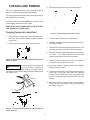
INITIAL SET-UP
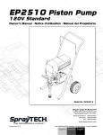
The SprayTech EP2300 Piston Pump unit is fully assembled upon delivery. Follow these
simple steps for set-up:
CART MOUNT/LOW BOY
LOWBOY
1. Remove the plug from the inlet elbow on the fluid
section.
2. Attach the suction set fitting into the inlet elbow on the
fluid section.
3. Attach the return line to the tube fitting at the dump
valve.
4. Remove protector cap on outlet fitting and install airless hose. DO NOT INSTALL SPRAY TIP(S) IN
GUN(S) AT THIS POINT.
Figure 1. SprayTech EP2300 Cart Mounted Piston Pump
1. Attach handle to cart using bolts and knobs provided.
Insert bolt through square hole in handle and then
through hole in cart leg. Secure with knob. Repeat
other side.
2. Remove protector cap on outlet fitting and install airless hose. DO NOT INSTALL SPRAY TIP(S) IN GUN(S)
AT THIS POINT.
SprayTech EP2300 Low Boy Piston Pump
Figure 2. Install Siphon Tube
7
PURGING AND PRIMING
4. Set Prime/Spray Ball Valve to the Prime position.
This unit is shipped with test fluid in the fluid section to
prevent corrosion during shipment and storage.
For spraying with solvent-based paint, thorough flushing of
this material is not necessary.
If you are going to spray with LATEX paint, this fluid must
be thoroughly cleaned out of the system.
KEEP SPRAY GUN LOCKED AND IN THE OFF POSITON DURING ALL THESE STEPS.
Purging System for Latex Paint
Figure 5. Set Prime/Spray Ball Valve to Prime
1. Place a bucket of soapy water under the paint suction
tube. Also, have a waste container handy to catch the
purged fluid.
5. Turn the ON-OFF switch to the ON position.
6. Gradually increase pressure by turning Pressure Control Knob clockwise.
2. Place paint return hose into the waste container.
7. Watch for fluid to start coming through return tube. Use
minimum pressure necessary to keep fluid flowing.
8. When test fluid is purged, soapy water will flow through
the return. Turn pressure down to minimum and
replace soapy water bucket with clear water.
Figure 3. Place return hose so purged fluid goes into
waste container.
9. Increase pressure again and let unit run until water
running through the return line is clear.
If a metal container is used, ground
the gun by holding it against the
edge of the container while flushing (As shown below).
Failure to do so may lead to static electric discharge, which
may cause a fire.
10. Decrease pressure. Replace clean water container
with bucket of latex paint.
WARNING
11. Increase pressure slowly until paint comes through the
return tube. Place return hose back into operating
position above paint bucket. Keep recirculating until
the paint coming through the return tube is free of air
bubbles.
12. Decrease pressure to minimum setting (counter-clockwise). The unit is now ready to use. (See “Operating
the Sprayer, page 9.)
Figure 4. Turn Pressure Control Knob Counter-Clockwise to
Reduce Pressure
8
For a new unit, follow purging and priming steps above. For
units already in service, also purge water or solvent from
the system as described above, depending on the type of
paint being used.
Purging System for Solvent-Based
Paint
If you are going to spray solvent-based paint, all you need
to do is purge the fluid. Thorough cleaning is not necessary
as it is with latex paint.
After pump is primed and ready to spray, it may also be
necessary to purge the hoses of water or solvent.
NOTE: KEEP SPRAY GUN LOCKED OFF DURING
ALL THESE STEPS.
1. Set Pressure Control Knob to minimum setting (counterclockwise).
1. Put full paint bucket into position.
2. Set Prime/Spray Ball Valve to Spray .
2. Place return hose over waste container. (See Figure
3.) Attach paint hose without tip and put into waste
container.
3. Be sure spray gun still has no tip installed.
4. Unlock spray gun.
3. Set Pressure Control Knob full counter-clockwise (minimum pressure). (See Figure 4.)
5. Increase pressure by turning Pressure Control Knob
clockwise.
4. Set Prime/Spray Ball Valve on Prime . (See Figure 5.)
6. Trigger gun into waste container until solvent or water
is purged from the hose.
5. Turn the ON-OFF switch to the ON position.
6. Turn Pressure Control Knob clockwise to increase
pressure until fluid starts to come through return tube
into waste container.
7. Decrease pressure by turning Pressure Control Knob
counter-clockwise.
8. Set Prime/Spray Ball Valve to Prime, and trigger gun
to be sure no pressure is left in the hose.
7. When paint starts to flow through return tube, decrease
pressure to minimum setting and place return tube over
paint bucket.
9. Lock gun off.
10. Install spray tip appropriate for the material being
sprayed. (The thicker the paint, the larger the spray tip
required.)
8. Continue recirculating until paint flowing through return
tube is free of bubbles.
9. Install spray tip.
11. Re-set Prime/Spray Ball valve to Spray.
10. You are now ready to spray.
12. Increase pressure to maximum setting (turn Pressure
Control Knob clockwise).
OPERATION
13. Release gun lock.
14. Trigger gun to test spray pattern. Spray against a scrap
piece of pasteboard or other test surface.
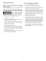
Before starting spraying every day, squirt upper packing
lubricant (Part No. 9992504) into slots in packing nut cover.
Do not apply so much that it overflows and drips into the
paint. This lubricant keeps the piston seals pliant, minimizing paint by-pass and piston wear. If unit is operated
several hours a day, repeat lubrication after about 4 hours.
15. See Setting the Pressure, below.
Setting the Pressure
The best pressure setting will vary with the type of paint and
the size and type of nozzle. The thicker the paint, the higher
the pressure needed.
To find the optimum pressure setting, start with the Pressure Control Knob turned fully clockwise (maximum pressure). Gradually decrease the pressure by turning the knob
counter-clockwise to the minimum level necessary to maintain the desired spray pattern and atomization.
Until you are satisfied with the spray pattern, spray on a test
surface rather than on the surface to be painted.
Figure 6. Oil Upper Pump Packings
9
Using the Spray Gun
Prime the Sprayer with Paint
1. Turn the prime/spray ball valve to prime.
NOTE: FOLLOW THE INSTRUCTIONS THAT CAME
WITH YOUR GUN.
2. Put the suction tube into the paint container.
3. Turn the pressure control knob counterclockwise as far
as possible to the lowest pressure setting.
4. Start motor. Slowly increase pressure by turning the
pressure control knob clockwise until pump begins to
function. When paint begins to flow through return tube
decrease pressure by turning the pressure control
knob counterclockwise and then turn the prime/spray
ball valve to the spray position.
PRESSURE RELIEF PROCEDURE
Be sure to follow the Pressure
Relief Procedure when shutting
the unit down for any purpose, including servicing or
adjusting any part of the spray system, changing or
cleaning spray tips, or preparing for clean-up.
WARNING
5. Disengage the gun safety latch.
6. Hold a metal part of the gun firmly against and aimed
into a metal waste container. Trigger the gun and hold
it open while slowly increasing the pressure setting by
turning the pressure control knob clockwise until the
sprayer starts. Keep the gun triggered until all the air
is forced out of the system and paint is flowing freely.
Release the trigger and engage the safety latch.
1. Engage the gun safety latch.
2. Shut off the motor and turn the pressure control knob
counterclockwise as far as possible.
3. Turn the prime/spray ball valve to prime, having a pail
ready to catch the drainage or return to the paint
container via the return hose.
7. Check all fluid connections for leaks. If any are found,
follow the pressure relief procedure before tightening
the connection.
4. Disengage the gun safety latch.
5. Hold metal part of the gun firmly to the side of a metal
pail to avoid a build up of static electricity, and trigger
the gun into the metal container to relieve the pressure.
6. Engage the gun safety latch.
7. Leave the prime/spray ball valve on prime, until you are
ready to operate the sprayer again.
10
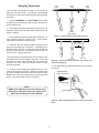
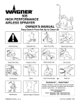
Spraying Technique
Light
Coat
Heavy
Coat
You can learn to spray paint as easily as you can learn to
paint with a brush or roller. You can get a professional
looking job in a safe manner by following the spray painting
tips below.
Light
Coat
Work
1. Heed all WARNINGS and CAUTIONS that are listed
on pages 3 thru 6 at the front of this manual. Take time out
now to reread them.
2. Avoid sharp bending and kinking of the paint hose. All
paint hoses should be kept clear of traffic and sharp cutting
edges or objects.
Wrong
Way to Spray
Figure 7. - Result of flexing wrist while spraying.
3. Use the lowest pressure possible when spraying. Too
much pressure shortens equipment life. It also causes
faster than normal wear on the spray tip.
Even Coat on Work Throughout
Approximatley
10 to 12 Inches
4. Determine the best spraying distance (distance from
spray tip on the spray gun to the work). If the spray gun is
held too close to the work, you will have paint buildup that
will cause sags and runs. If the spray gun is held too far
from the work, "fogging" will result.
The correct distance should be about 10 to 12 inches. Keep
this distance for the entire length of the stroke. Of course,
the shape of some work surfaces will not permit this.
However, the same spraying distance should be kept
whenever possible.
Right
Way To Spray
Steady Arm
Figure 8. - Result of smooth arm stroke and steady, even
speed while spraying.
6. Keep the spray gun perpendicular to the work as shown
in Figure 9.
5. Do not move the spray gun by flexing your wrist. The
result of this is shown in Figure 7. Rather, move the spray
gun with a smooth stroke of the entire arm and shoulder.
Maintain the same arm speed all the way through the
stroke. The result of this is shown in Figure 8.
Approximately
10 to 12 inches
Right Way
NOTE:
WHEN SPRAYING BLOCK FILLER, MASTICS OR
HIGH SOLID COATING LEAVE OUT GUN FILTER
AND HIGH PRESSURE FILTER SCREENS.
Wrong Way
Figure 9. - Right and wrong ways to hold spray gun toward
work.
11
7. The spray gun should be triggered (turned off and on)
on each stroke. This will save paint and avoid paint
buildup at the end of the stroke. However, do not trigger
during the middle of a stroke. This will result in an
uneven spray and splotchy work. See Figure 10 for
proper triggering on a left-to-right stroke. Reverse for
a right-to-left stroke.
CLEAN-UP
The pump, hose and gun should be
cleaned thoroughly after daily use.
Failure to do so permits material to cake, seriously affecting
the performance of the unit.
CAUTION
When cleaning the pump, hose
and gun with mineral spirits or any
other solvent, ALWAYS spray at minimum pressure with
the gun nozzle tip removed. Static electricity build-up may
result in a fire or explosion in the presence of flammable
vapors.
8. Move the spray gun at a rate of speed that is comfortable for you. If you have to move your arm too fast in
order to prevent excessive paint buildup, either (1)
lower the pressure by turning the pressure control knob
counterclockwise, or (2) use a spray tip with a smaller
hole. If you have to move your arm too slow in order to
get a good coating, either (1) raise the pressure by
turning the pressure control knob clockwise, or (2) use
a spray tip with a larger orfice. You should always keep
the spray gun moving when making a stroke. Slowing
down in one place will cause sags or runs.
WARNING
After daily use, paint should be flushed from the unit with
solvent compatible with the material applied, and then reflushed with mineral spirits.
1. Turn power switch to OFF.
Approximatley
10 to 12 Inches
2. Bleed off any pressure remaining in the pump by
opening the dump valve.
Work
Even Steady
Stroke
Start
Stroke
Pull
Trigger
3. Remove gun tip and clean with solution compatible
with material applied.
End
Stroke
Release
Trigger
4. Remove paint container from its position directly below
siphon hose and paint strainer. Replace with a container of solvent compatible with material being applied.
Figure 10. - Proper way to trigger spray gun.
5. Turn the pressure control knob counter-clockwise to
the lowest pressure setting.
9. Overlap each stroke by about 40% to 50%. The
overlap will assure a paint coating that is uniform
across the work. One way to get good overlap is to
point the spray gun at the edge of the last stroke.
6. Turn power switch to ON.
7. Trigger spray gun(s) into container to flush pump, hose
and gun(s) clean.
8. Turn power switch to OFF.
9. Bleed off solvent.
10. Unplug unit and store in a clean dry area.
For long-term storage, be sure to flush unit with appropriate
oil before storing.
12
MAINTENANCE
Routine operator maintenance on this unit is minimal. Only
three daily procedures are required: (1) lubricating the
upper packings, (2) cleaning the high pressure filter screen,
and (3) cleaning the intake screen.
Filter
Housing
Filter
Support
Daily Maintenance
O-Ring
1. Squirt upper packing lubricant into slots in upper pump
housing. Do not over-lubricate, as this will result in oil
dripping into the paint. Oil approximately every four
hours of operation.
Filter
Element
Figure 12. Remove and clean High-Pressure Filter at
least daily, more often if needed.
3. Inspect paint intake screen (at bottom of paint suction
tube) and wash if necessary. (Screen is threaded onto
suction tube. Remove by turning counter-clockwise.)
Teflon tape
Siphon tube
Figure 11. Squirt upper packing lubricant into upper cylinder
housing every four hours.
2. Clean high pressure filter, as needed. Remove filter
housing. (Filter canister is threaded into base with
right-hand threads.) Take out filter element and wash
thoroughly. Scrub gently with a fiber-bristle brush if
necessary (DO NOT use a wire brush). If spraying
block fillers, mastics, etc. leave filter element out.
Screen
Figure 13. Clean paint intake screen daily, or more often if
needed.
13
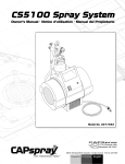
Repacking the Fluid Section
ALWAYS follow the Pressure
Relief Procedure (page 10)
before starting any troubleshooting, servicing, or cleaning.
A small amount of paint by-passing the piston and coming
out of the slots in the upper piston housing is normal, but if
it becomes excessive, or if paint pressure drops, the piston
packings need to be replaced.
WARNING
Refer to Figure 14 (left).
1. Loosen and remove siphon tube assembly by turning
counterclockwise.
1
*2
*4
2. Remove front cover.
*3
3. Remove packing nut cover.
*5
*6
4. Run the unit in short intervals until the connecting pin
is in front of the recessed area of the housing.
7
5. Disconnect the power cord from the electrical supply.
6. Remove the retainer clip on the yoke.
7. Remove the connecting pin by pushing it through the
yoke and piston rod.
8
8. Loosen and remove fluid hose.
*9
9. Loosen large locknut (7) on upper end of fluid section.
10. Unscrew entire fluid section assembly by turning counterclockwise.
10
CAUTION
11. Using wrench flats on inlet valve holder (28), position
fluid section vertically into vise. Tighten vise.
*11
*13
*12
*14
15
* Included in Packing Kit
P/N 0294905.
12. Locate wrench flats on cylinder (8). Turn cylinder
counterclockwise with large adjustable wrench until it is
removed from the inlet valve holder (28).
# Included in Valve Kit
P/N 0294689.
13. Remove and inspect upper O-Ring (22) in inlet valve
holder. If damaged, replace when re-installing.
14. Remove inlet valve holder (28) from vise. Tap out ball
stop disc (23), ball cage (25) and ball (24).
16
*#17
#18
20
Do not run motor with fluid section
removed.
*#19
If any parts are difficult to disassemble, soak in
lacquer thinner until paint softens.
21
*#22
15. Remove lower ball seat (26). Inspect the ball and ball
seat for damage. If seat is worn or damaged it can be
flipped to the unused side. Ball must be replaced if
damaged or if the seat is flipped.
23
*#24
25
NOTE:
#26
*#27
Inlet and Outlet Valve carbide seats are reversible.
If one side becomes worn or damaged, flip the seat
to the un-used side.
28
Figure 14 - Fluid Section
©1994, rev. 1995 Wagner Spray Tech Corporation. All rights reserved.
Continued on next page.
14
Repacking Fluid Section
34. Soak new leather packings in linseed oil for 5 minutes.
Do not oversoak.
Continued from Page 14
35. Insert wave spring (9) and lower male adapter (11) into
cylinder. Remove leather packings from oil. Install
leather packings (13) alternatively with UHMWPE
packings (12). Insert lower female adapter (14).
(Refer to Figure 14, Page 14)
16. Remove lower O-Ring (27) from inlet valve holder.
17. Place cylinder (8) in vise (on wrench flats) and
tighten.
CAUTION
36. Insert piston assembly into bottom of cylinder (8). A
slight force may be required to push piston rod through
packings.
Do not over tighten or damage to
cylinder may occur.
37. Place O-Ring (27), lower ball seat (26), ball cage (25),
ball (24) and lower ball stop disc (23) into inlet valve
holder (28).
18. Remove packing nut (1).
19. Gently hammer piston assembly down with rubber
mallet. Piston assembly will come out.
38. Put anti-seize compound on lower threads of cylinder
(8). Put O-Ring (22) on cylinder. Loosen vise and tilt
cylinder assembly at about a 45 degree angle. Tighten
vise again.
Hold hand under piston rod (10).
Damage can occur if piston rod
falls to the floor. Lower packings may also fall out.
CAUTION
21. Remove lower male adapter (11) and wave spring (9).
39. Tighten foot valve holder assembly onto cylinder with
an appropriate adjustable wrench until cylinder bottoms
out in foot valve holder. Make sure to use wrench flats
on foot valve holder to tighten completely. Torque to 40
ft./lbs.
22. Remove upper packings (3, 4 ) and adapter (2, 5) and
wave spring (6).
40. Soak remaining new leather packings in linseed oil for
5 minutes. Do not oversoak.
23. Insert connecting pin through hole in piston rod (10).
Lock connecting pin in vise jaws so piston rod is
vertical. DO NOT put piston rod itself in vise. The vise
jaws will damage piston rod.
41. Insert wave spring (6), upper male adapter (5). Remove
leather packings from oil. Install leather packings (4)
alternatively with UHMWPE packings (3). A tool, Wagner
part #06009, may be required to compress packings
down. Insert female adapter (2).
20. Remove lower packings (12, 13) and lower female
adapter (14) if they have not already fallen out.
24. Remove jam nut (21).
42. Install packing nut (1) and tighten until the nut bottoms
out in cylinder. Torque to 25 ft./lbs. Do not overtighten.
25. Remove piston seat retainer (20) with 5/16'' allen
wrench.
26. Remove piston rod assembly from vise.
43. Install large locknut (7) onto upper cylinder (8) and
turn until nut bottoms out on threaded section of
cylinder.
27. Remove washer (19), ball seat (18), ball (17), ball
cage(16) and ball stop disc (15) from lower end of
piston rod assembly.
44. Put anti-seize compound on upper cylinder threads.
28. Inspect ball, and ball seat for damage. If the seat is
worn or damaged it can be flipped to the un-used side.
Ball must be replaced if damaged or the seat is flipped.
Washer must be replaced.
45. Remove fluid section from vice and install into main
pump housing. Piston rod (10) will align itself inside
yoke.
46. Rotate fluid section slightly to align hole in yoke and
hole in piston assembly. Insert connecting pin.
Replace spring retainer.
29. Hold piston assembly in vice using same procedure as
step 23.
30. Insert upper ball stop disc (15), ball cage (16), ball (17),
ball seat (18), and washer (19) into piston assembly.
47. Thread fluid section into pump housing completely,
then unscrew up to 3/4 turn to align outlet elbow with
fluid hose.
31. Put removable loctite on piston seat retainer (20).
Insert into piston assembly and tighten. Torque to 250
in./lbs.
48. Rotate large locknut (7) clockwise until tight against
drive housing.
32. Put removable loctite on jam nut (21). Tighten onto
piston seat retainer. Torque to 200 in./lbs. Remove
piston assembly from vice.
33. Place cylinder in vice using wrench flats and tighten.
15
WARNING
NEVER OPERATE PUMP WITHOUT FRONT COVER IN
PLACE.
Motor Brush Replacement
Brushes should be inspected periodically to insure uninterrupted service. Their life depends on speed as well as load.
Brush Cap
If one of the brushes measures less than 1/4'' or is worn
roughly or chipped, replace both motor brushes. It is also
recommended that brushes be checked when packings are
replaced.
1. Disconnect power cord from electrical supply.
Motor Brush
2. Remove the four (4) motor shroud mounting screws
and remove the motor shroud.
Figure 15. Remove Brush Cap and Motor Brush
3. Unscrew and remove brush caps holding brushes in
place.
4. Remove brushes.
6. Replace brush caps.
5. Replace with new brushes.
7. Replace motor shroud and screws.
16
TROUBLESHOOTING
PROBLEM
CAUSE
REMEDY
Unit will not run
Blown panel fuse or tripped
breaker
Unit not plugged in
Pressure control knob set too low
Faulty or loose wiring
Check and replace/reset
Worn motor brushes
Clogged Tip or Filters
Faulty On/Off switch fuse
Unit will not prime
Dried out piston packings
Remove siphon tube and feel lower ball check to
be sure it is free to move off its seat. Place full
cup of paint thinner over end of fluid section and
turn on pump.
Remove and clean.
Hold gun trigger in open position and run unit
about 10 seconds until air is purged
Check for siphon tube leak
Replace packings. (See page 14)
Prime pump with compatible solvent. Bring pump
up to pressure. Carefully remove pump from
solvent container and immerse inlet tube in heavy
material to be sprayed. With nozzle tip removed,
trigger gun until heavy material appears at gun.
Replace nozzle tip.
Remove and clean
Check connection and seal
Relieve pressure, remove tip and clean.
Pump inlet screen plugged
Air in pump or hose
Packings worn
Fluid is too viscous
Siphon tube clogged
Siphon tube air leak
Clogged tip
Unit will not build or
maintain pressure
Pressure adjusting knob not
properly set
Pump inlet strainer dirty
Valve balls or seals worn or dirty
Air in pump or hose
Packings worn
Worn spray tip
Internal leakage
Fluid leak
Fluid too viscous
Spray tip too large
Fluid leakage at upper
end of fluid section
Plug in
Turn knob to higher pressure
Inspect/Take to SprayTech Authorized Service
Center
Check and replace brushes
Clean tip and filters.
Take to SprayTech Authorized Service Center
Upper packing worn
Adjust to increase pressure
Clean
Replace or clean
Hold gun trigger in open position and run about 10
seconds until air is purged
Replace (See Page 14)
Replace (Follow direction supplied with gun)
With gun trigger closed, allow unit to pump up to
pressure and shut off if pump momentarily starts.
Internal leak is indicated and fluid section rebuild
is necessary. (See Page14)
Check for external leaks including hydraulic
fittings attached to pressure control housing
Consult manufacturers recommendations on paint
container label
Change tip
Relieve pressure and tighten packing take up nut
or replace packings. (See Page 14)
Replace. (See Page 14)
Piston rod worn
17
TROUBLESHOOTING CONTINUED
PROBLEM
CAUSE
REMEDY
Poor spray pattern
Tip too large
Pressure adjustment wrong
Insufficient fluid delivery
Fluid too viscous
Change to smaller tip
Adjust pressure control knob
Clean all strainers and filters
Add solvent according to manufacturer's
recommendations
Unit lacks power
Pressure adjustment low
Improper voltage supply
Increase pressure
Reconnect input voltage for 115 AC
Blow Fuses at Pump
Excessive pressure
Circuit Breaker
Overtightened packings
gear box, linkage or motor
failures
Take to SprayTech Authorized Service
Center
Repair/replace malfunctioning parts
18
26
20
25
24
3
4
2
23
5
1
22
15 14
9
10
21
7
8
6
6
20
19
18
13
12
9
10
17
11
16
2
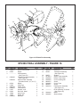
Figure 16- EP2300 Final Assembly
EP2300 FINAL ASSEMBLY - FIGURE 16
ITEM PART NO.
1
2
3
0294611
05045
--------
4
0294220
0294229
5
6
7
8
9
10
11
12
13
02518
51055
9885563
0294416
51357
52183
13549
12440
0294415
DESCRIPTION
QTY
Hose, Fluid,1/4 NPT
Nipple
Cart Assembly
(See Figure 18)
Filter/Dump Valve Assembly
(See Figure 26)
Optional Filter Assembly
(Includes Items 2, 4, 5, 6 & 7)
Nipple
Plug, Pipe
Fitting, Tube
Tube, Return
Washer, Lock
Bolt, Hex. Head
Hose, Fluid
Elbow, 90°
Manifold
ITEM PART NO.
1
2
1
1
1
2
1
1
4
4
1
1
1
19
14
15
9885547
02208
16
17
18
19
20
21
22
23
02975
0279473
0294584
0294393
9802515
0294425
9802511
0294133
24
------------
25
26
0294344
0294405
DESCRIPTION
Elbow 45°
Transducer Assembly
(See Figure 22)
Strainer
Siphon Tube Assembly
Return Tube Clamp
Cover, Packing Nut
Screw
Cover, Front
Screw
Fluid Section Assembly
(See Figure 21)
Drive Assembly, 23 Series
(See Figure 25)
Baffle
Shroud, Motor
QTY
1
1
1
1
1
1
6
1
5
1
1
1
1
24
18
23
22
8
9
5
21
6
1
10
20
11
12
17
7
19 18
6
16
2
3
13
15
14
4
3
2
4
5
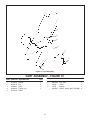
Figure 17- Low Boy Final Assembly
EP2300 LOW BOY FINAL ASSEMBLY - FIGURE 17
ITEM
PART NO.
1
--------
2
3
4
5
6
7
8
51357
52183
13549
05045
51055
02518
0294220
0294228
9
10
11
12
9885559
0294424
9885547
02208
DESCRIPTION
QTY.
ITEM
LowBoy Cart Assembly
1
(See Figure 19)
Washer, Lock
4
Bolt, Hex. Hex.
4
Hose, Fluid
2
Nipple
2
Plug, Pipe
2
Nipple
1
Filter/Dump Valve Assembly
1
(See Figure 26)
Optional Filter Assembly
( Includes Items 5, 6, 7, 8, & 9)
Elbow, 90°, Return Line
1
Tube, Return
1
Elbow, 45°
1
Transducer Assembly
1
(See Figure 22)
20
PART NO.
13
14
15
16
12440
0294415
0090447
0294133
17
18
19
20
0294393
9802515
0294425
0294185
21
22
9802511
-------
23
24
0294344
0294405
DESCRIPTION
Elbow, 90°
Manifold
Elbow, 90°
Fluid Section Assembly
(See Figure 21)
Cover, Packing Nut
Screw
Cover, Front
Suction Set
(See Figure 23)
Screw
Drive Assembly 23 Series
(See Figure 25)
Baffle
Shroud, Motor
QTY.
1
1
1
1
1
6
1
1
5
1
1
1
1
2
3
4
5
6
7
8
Figure 18 - Cart Assembly
CART ASSEMBLY - FIGURE 18
ITEM PART NO. DESCRIPTION
1
2
3
4
5
0279324
9802518
0288661
0294558
0270318
Handle
Bolt
Knob
Frame, Cart
Wheel
ITEM PART NO. DESCRIPTION
QTY.
1
2
2
1
6
7
8
21
9890104
54458
13538
0294534
Cap, Axle
Screw
Bumper
Spacer, Wheel (NOT SHOWN)
QTY.
2
2
2
4
1
2
3
4
5
4
7
6
8
Figure 19- LowBoy Cart Assembly
LOWBOY CART ASSEMBLY - FIGURE 19
ITEM PART NO. DESCRIPTION
1
2
3
4
0294445
9802518
0288661
0294534
Handle, Cart
Bolt, Carriage
Knob, Handle
Spacer, Wheel
QTY.
ITEM PART NO. DESCRIPTION
5
6
7
8
1
2
2
4
22
0270318
9890104
0294579
0270343
Wheel
Cap, Hub
Cart
Foot, Rubber
QTY.
2
2
1
2
1
8
2
7
3
4
6
5
18
19
20
17
21
10
9
14
13
16
11
15
12
Figure 20 - Pressure Control Assembly
PRESSURE CONTROL ASSEMBLY - FIGURE 20
Item
1
2
3
4
5
6
7
8
9
10
11
Part No.
Description
0294837
0295426
02585
0089986
0294349
0275703
9850630
52671
0294428
02491
9850629
02712
0294359
Pressure Increase Label
Knob
Toggle Boot
On/Off plate
Housing
Strain relief
Strain relief (CSA)
Ring terminal
Cord set
Cord Set (CSA)
Strain relief
Spring
Plunger
Qty.
Item
1
1
1
1
1
1
1
1
1
1
1
1
23
Part No.
Description
12
02208
13
14
15
16
17
18
19
20
21
9822522
03662
0294132
9800604
9851311
53280
53732
18066
50520
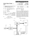
Transducer assy.
(See Figure 23)
Retainer ring
Switch spacer
Pressure Switch Assembly
Screw
Lead wire
On/Off switch
Fuse (10 amp)
Relay (25 amp)
Screw
Qty.
1
1
1
1
2
1
1
1
1
3
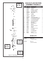
0294133 FLUID SECTION
ASSEMBLY FIGURE 21
NOTE:
#1 Torque
25 FT. LBS.
1
ITEM
PART NO
DESCRIPTION
1
2
3
4
5
6
7
8
9
10
11
12
13
14
15
16
17
18
19
20
21
22
23
24
25
26
27
28
0294319
0294377
08180
00078
0294376
0294379
00302
0294318
13364
0294316
0294326
08070
09091
0294375
13458
13357
50164
13359
09446
13481
13482
13381
13380
51519
00311
00310
00203
13403
Packing nut
Adapter
Packings, UHMWPE
Packings, leather
Upper male adapter
Wave spring
Locknut
Cylinder
Wave spring
Piston rod
Lower male adapter
Lower packings, UHMWPE
Lower packings, leather
Lower female adapter
Upper ball stop disc
Upper ball cage
Upper ball
Upper ball seat
Washer
Piston seat retainer
Jam nut
O-ring
Lower ball stop disc
Lower ball
Lower ball cage
Lower ball seat
O-ring
Inlet valve holder
QTY.
*2
*4
*3
*5
*6
7
8
*9
10
*11
*13
*12
*14
15
16
20
REPAIR KITS
*#17
#18
*#19
21
*#22
23
*#24
NOTE:
#21 Torque
200 IN./LBS.
25
NOTE:
#20 Torque
250 IN. LBS.
# 26
*#27
28
NOTE:
#28 Torque
40 FT. LBS.
Figure 21 - Fluid Section
24
KIT NO.
DESCRIPTION
0294905
Packing Kit
(* Items Included)
0294689
Valve Kit
(# Items Included)
1
1
3
2
1
1
1
1
1
1
1
3
2
1
1
1
1
1
1
1
1
1
1
1
1
1
1
1
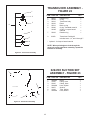
TRANSDUCER ASSEMBLY FIGURE 22
1
ITEM PART NO. DESCRIPTION
2
3
8
4
5
6
1
2
3
4
5
6
50431
50504
02216
02232
50512
50482
02305*
7
50423
8
02283
QTY
Retainer ring
O-ring
Transducer body
Piston
Back-up ring
O-ring - Standard material
O-Ring - Lacquer based
material
Retainer ring
1
1
1
1
1
1
1
1
Transducer Packing Kit
Includes Items 1, 2, and 4 through 7.
* Optional - for lacquer based material
7
NOTE: When paint begins to leak through the
weep hole on the transducer assembly, repack the
transducer assembly.
Figure 22 - Transducer Assembly
0294185 SUCTION SET
ASSEMBLY - FIGURE 23
7
ITEM PART NO. DESCRIPTION
1
2
3
4
5
6
7
1
6
5
2
4
3
Figure 23 - Suction Set Assembly
25
0090447
13455
53635
0294426
02975
13463
0294424
Elbow
Fitting, Hose
Clamp, Hose
Hose, Siphon
Strainer
Tube, Siphon
Hose, Return
QTY
1
1
1
1
1
1
1
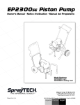
EP2300 MOTOR ASSEMBLY - FIGURE 24
3
2
ITEM
1
2
3
4
5
6
7
8
9
10
1
4
PART NO.
DESCRIPTION
01678
01694
01686
01783
19498
50148
50865
01791
50962
*01961
Brush Holder
Motor Brush
Brush Cap
Stud
Stator Assy.
#10 Lockwasher
10-32 Nut
Belleville Washer
Bearing-Commutator End
Armature w/Bearings
5
* Includes #50962 Bearing
6
6
7
7
8
9
8
10
9
NOTE: Washers
must be stacked
as shown.
6
7
EP2300 Motor Assembly - Figure 24
26
QTY.
2
2
2
2
1
4
4
4
2
1
6
4
3
9
8
7
5
10
2
1
7
6
15
39 40
14
11
13
16
38
37
18
17
36
35
19
24
34
33
32
22
25
31
30
27
21
20
23
26
12
29
28
EP2300 Drive Assembly - Figure 25
EP2300 DRIVE ASSEMBLY - FIGURE 25
ITEM
PART NO.
DESCRIPTION
1
2
3
4
5
6
7
8
9
10
11
0294349
05304
11177
51837
51845
11843
53074
05282
50547
0294154
50318
50113
05208
05207
50717
19015
17183
50989
05223
50997
50008
Housing
Key
Crankshaft
Bearing
Ring, Retainer
Washer
Screw
Gear
Bearing
Motor with Pinion
Screw
Washer
Gear Set
Pinion
Spring Pin
Gear Case
Gasket
Bearing
High Speed Cluster
Bearing
Ball, Stainless
12
13
14
15
16
17
18
19
20
QTY.
1
1
1
1
1
2
2
1
1
1
13
13
1
1
1
1
1
1
1
1
1
27
ITEM
PART NO.
DESCRIPTION
21
22
23
24
50962
05274
50954
53074
25
26
27
28
29
30
31
32
33
34
35
36
37
38
39
40
0294402
0294365
0294394
0294301
0294302
51187
0294606
0294366
0294367
0294364
50555
0294604
0294410
0294368
0294602
0294446
Bearing
Low Speed Cluster
Bearing
Screw
Washer, Lock
Plate, Adapter
Pin, Yoke
Gasket
Retainer. Spring
Pin, Connecting
Ring, Retainer
Yoke
Bearing
Bearing
Bushing
Bearing
Rod, Connecting
Bolt, Shoulder
Bearing
Drag Line
Washer
QTY.
1
1
1
6
6
1
1
1
1
1
2
1
1
2
1
1
1
1
1
1
1
1
2
3
4
5
6
7
8
9
∆
∆
1
2
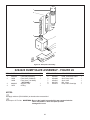
Figure 26 - Dump Valve Assembly
0294220 DUMP VALVE ASSEMBLY - FIGURE 26
ITEM
PART NO.
DESCRIPTION
1
2
0294194
14069
14068
3
4
9894245
14072
Filter Body Assembly
Filter Sieve (50 Mesh)
Filter Sieve (100 Mesh)
(OPTIONAL)
Support, Filter
O-Ring
QTY.
ITEM
1
1
5
6
7
8
9
1
1
PART NO.
DESCRIPTION
0294555
0294499
0294516
9841502
0294214
Head, Filter/Dump Valve
Seal, Dump Valve
Seat, Valve
Ball, 10mm
Dump Valve Cartridge
NOTES:
∆ Apply antisieze (P/N 0093930) to threads when reassembled.
∆ Torque to 35 Ft./Lbs. CAUTION: Be
sure the handle is turned all the way counterclockwise
when reassembled. Valve seat (item 6) will be
1
2
damaged if it is not.
28
QTY.
1
1
1
1
1
1
2
3
4
5
6
{∆∆
1
See Note Page 28
2
Figure 27 - Dump Valve Assembly
DUMP VALVE ASSEMBLY - FIGURE 27
Item
Part No.
Description
Qty.
1
2
3
0294502
0294966
0294499
Housing, Dump Valve
Repair Kit
Seal, Dump Valve
1
1
1
Item
4
5
6
Part No.
0294516
9841502
0294214
Description
Seat, Valve
Ball, 10mm
Dump Valve Cartridge
Qty.
1
1
1
1
2
3
4
5
6
Convex
7
Concave
Convex
8
Figure 28 - Dump Valve Cartridle
DUMP VALVE CARTRIDGE - FIGURE 28
Item
1
2
3
4
Part No.
Description
9871046
0294498
9871045
0294500
O-Ring
Body, Dump Valve
O-Ring
Stem, Dump Valve
Qty.
Item
1
1
1
1
5
6
7
8
29
Part No.
Description
0294501
9822516
0294788
0291512
Washer, Dump Valve
Ring, Retainer
Washer, Kit, Bellville
Handle, Dump Valve
Qty.
1
1
4
1
ACCESSORIES
GUN FILTERS
Part
Number Description
0153——
0153003
0291004
0291003
0291002
0291000
0093896
0088154
0153043
0153042
0152001
0152308
0152307
0152309
0152310
0152235
0152236
0152237
0152238
0152700
0149017
0093930
0152909
0152900
0502007
0502008
0502009
0270214
0502012
Part No.
Tungsten Carbide Flat Tips
Tip Guard, Flat Tip
Hose, Whip End, 3' x 3/16"
Hose, Whip End, 5’ x 3/16”
Hose, Wireless, 25’ x 1/4"
Hose, Wireless, 50’ x 1/4"
Hose Connector, 1/4” x 1/4”M
Pressure Gauge
Tip Extension, 6” (fits 11/16” diffuser)
Tip Extension, 12” (fits 11/16” diffuser)
Power Roller Gun Attachment
9" Roller Cover, 3/8” Nap
9" Roller Cover, 1/2” Nap
9" Roller Cover, 3/4” Nap
9" Roller Cover, 1-1/4” Nap
12" Roller Cover, 1/2" Nap
12" Roller Cover, 3/8" Nap
12" Roller Cover, 3/4" Nap
12" Roller Cover, 1-1/4" Nap
Adapter, Power Roller Extension
G-10 Four Finger Airless Spray Gun (no tip)
Anti-Seize Compound
R-10 Telescoping Roller, 9", 3/8" Nap
R-10 Telescoping 12" Roller, 3/8" Nap
G-10 Four Finger Airless Spray Gun with 517
Reversible Tip
G-10 Two Finger Airlesss Spray Gun (no tip)
G-10 Two Finger Airless Spray Gun with 517
Reversible TIp
G-10 Four Finger Spray Pack with 50’ x 1/4”
airless hose
G-10 Two Finger Spray Pack with 50” x 1/4”
Airless Hose
0089960
0089959
0089958
0089957
30
Application
Synthetic resin
enamels, clean
varnishes, stains
azures
Filter
Type
Extrafine 0.084 mm
Base coat enamels
primer enamels
fillers, marking paints, Fine
textujred enamesls
Emulsions
Latex-paints
acrylic-paints
Filler paints,
large area surfaces
Mesh
Number
Color of
Fiilter Body
Red
0.140 mm
Yellow
Medium
0.315 mm
Green
Coarse
0.560 mm
White
Limited Warranty
Commercial Airless Spray Equipment
Two Year Warranty
Spray Tech, a division of Wagner Spray Tech Corporation ("Spray Tech"), warrants this product against defects in material and
workmanship for a period of two years following the date of purchase by the original purchaser. During that period, Spray Tech will repair
or replace any defective or worn-out component or, at Spray Tech’s option, refund to the original purchaser the full purchase price for
the product in exchange for the return of that product. However, Spray Tech will not replace or repair any fluid pump component on account
of wear more than twice during the two year warranty period. This warranty does not cover consumable products such as filters and tips.
Lifetime Warranty on Gear Trains, Electric Motors, and Gas Engines
Spray Tech warrants any gear train, electric motor (excluding brushes) and gas engine (excluding the clutch) in this product against
defects in material and workmanship for the lifetime of the original purchaser. If Spray Tech determines that the foregoing warranty has
been breached, Spray Tech will repair or replace the defective components without charge or, at Spray Tech’s option, refund to the original
purchaser the full purchase price for the product in exchange for the return of that product.
Warranty Claims
Any request for repair or replacement pursuant to the warranties above must be accompanied by the return of the applicable parts, with
transportation charges prepaid, to a service center authorized by Spray Tech or to Wagner Spray Tech Corporation, 1770 Fernbrook Lane,
Minneapolis, MN 55447.
Limitation of Remedies
THE REMEDIES SET FORTH ABOVE ARE THE EXCLUSIVE REMEDIES AVAILABLE FOR BREACH OF EXPRESS AND IMPLIED
WARRANTIES. These remedies shall not be deemed to have failed of their essential purpose so long as Spray Tech is willing to repair
or replace parts, or to refund the purchase price, as set forth above.
What Is Not Covered By This Warranty
This warranty does not cover defects or damages caused by:
•
the use or installation of repair or replacement parts or accessories not manufactured by Spray Tech;
•
repair performed by anyone other than a Spray Tech Authorized Service Center; or
•
abuse, misuse, negligence, accident, faulty installation or tampering in a manner which impairs normal operation.
This warranty also does not cover equipment and accessories supplied to Spray Tech from an original equipment manufacturer, including
but not limited to hoses, tips, and accessories. Spray Tech will provide the purchaser with copies of the original equipment manufacturer’s
express warranties provided to Spray Tech along with the name and address of the appropriate manufacturer.
Limitation of Remedies
IN NO CASE SHALL SPRAY TECH BE LIABLE FOR ANY INCIDENTAL, SPECIAL OR CONSEQUENTIAL DAMAGES OR LOSS,
INCLUDING TRANSPORTATION COSTS, WHETHER SUCH DAMAGES ARE BASED UPON A BREACH OF EXPRESS OR IMPLIED
WARRANTIES, BREACH OF CONTRACT, NEGLIGENCE, STRICT TORT, OR ANY OTHER LEGAL THEORY.
Disclaimer Of Implied Warranties
THE FOREGOING WARRANTIES ARE IN LIEU OF ALL OTHER WARRANTIES, EXPRESS OR IMPLIED, INCLUDING BUT NOT
LIMITED TO THE IMPLIED WARRANTIES OF MERCHANTABILITY AND FITNESS FOR A PARTICULAR PURPOSE.
No Ability To Transfer
This warranty is extended to the original purchaser only and is not transferable.
Patents
These products are covered by one or more of the following patents:
5,228,842
5,192,425
D344,832
5,318,314
5,346,037
5,494,199
5,472,318
5,435,697
1770 Fernbrook Lane
Minneapolis, Minnesota 55447
Telephone 1-800-292-4637
Printed in U.S.A.
32
5,282,722
4,992,633
5,099,183