1
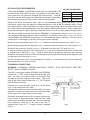
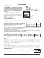
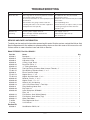
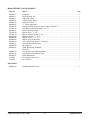
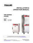
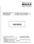
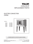
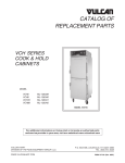
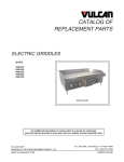
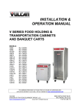
INSTALLATION &
OPERATION MANUAL
SCALEBLOCKERTM
WATER FILTRATION SYSTEM
MODEL
PART NO.
SPS600V
SPS620V
854893-1
854893-2
For additional information on Vulcan-Hart or to locate an authorized parts
and service provider in your area, visit our website at www.vulcanhart.com
VULCAN-HART
DIVISION OF ITW FOOD EQUIPMENT GROUP, LLC
WWW.VULCANHART.COM
P.O. BOX 696, LOUISVILLE, KY 40201-0696
TEL. (502) 778-2791
FORM 31228 Rev. A (Sept. 2004)
Installation, Operation and Care of
SCALEBLOCKER TM WATER FILTRATION SYSTEM
MODELS SPS600V & SPS620V
SAVE THESE INSTRUCTIONS
GENERAL
Vulcan water filters are produced with quality workmanship and material. Proper installation,
usage and maintenance of your water filter will result in many years of satisfactory performance.
It is suggested that you thoroughly read this entire manual and carefully follow all of the
instructions provided.
The water filtration system conforms to ANSI/NSF Standard 53 and ANSI/NSF Standard 42 for
the specific performance claims as verified and substantiated by test data.
Filter capacity will vary according to flow rate, influent water pressure and local water conditions.
Service life for the filter cartridge for model SPS600V is 7,500 gallons ( 28,390 liters ); for model
SPS620V, the service life for the filter cartridge is 15,000 gallons ( 56,780 liters ). Filter cartridge
replacement is recommended at least every 6 months to maintain equipment warranty. Filter
cartridge replacement is also recommended if water pressure goes below 20 psig ( 138 kPa ).
INSTALLATION
UNPACKING
The water filter was inspected before leaving the factory. The transportation company assumes
full responsibility for safe delivery upon acceptance of the shipment.
IMPORTANT: Immediately after unpacking, check for possible shipping damage. If the water
filter is found to be damaged, save the packaging material and contact the carrier within 15 days
of delivery.
TEST THE WATER AND RETURN THE RESPONSE CARD
Test the incoming unfiltered water supply with the enclosed 4-IN-1 City Water Check test strip by
carefully following the instructions on the package. Record the results on the enclosed Filter
Registration Card. Be sure and use the Vulcan-Hart Equipment model and serial number. Do
not use the filter system model and serial number. Fill the registration card out completely and
return the information to Vulcan in one of the following three ways: Mail the postage-paid selfaddressed card to Vulcan, FAX the completed card per instructions on the cord or contact Vulcan
on-line at www.vulcanhart.com , select service tab and answer all the necessary questions.
NOTE: Filter registration is required at time of installation to begin warranty coverage on the
equipment being installed with the filter.
LOCATION
The water filter should be mounted on a sturdy support structure or wall and must be level. Do
not mount the filter system directly on the steamer.
LEVELING
Use a carpenter's level to level the top of the water filter's mounting head.
© VULCAN-HART 2002, 2004
–2–
INSTALLATION REQUIREMENTS
WATER PARAMETERS
6 to 9
0 to 250 ppm
0 to 4 ppm
0 to 300 ppm
The model SPS600V and SPS620V water filters are designed to be p H
installed in the cold water line only. Installation of the water filter in Alkalinity
a hot water line can seriously damage the filter housing. The filter
Chlorine
must be in contact with water at all times after installation. Installation
Hardness
must comply with any existing state or local plumbing codes.
Refer to the Water Parameters table, right, for recommended water quality limitations. If your
local water supply does not meet the recommendations in the Water Parameters table, Vulcan
may request that a water sample be returned for laboratory testing. After evaluation of the water
test, other specific recommendations may be made for additional filtration or water treatment to
make the local water supply meet the acceptable limits for use in steam generator equipment.
The recommended incoming flow rate for SPS600V is 2 gallons per minute (7.6 liters per minute ).
The recommended incoming flow rate for SPS620V is 4 gallons per minute ( 15.1 liters per minute ).
The SPS600V and SPS620V water filters must be protected against freezing. Failure to do so
could result in breakage of the filter housing and water leakage.
Minimum operating temperature: 45°F ( 7°C ). Maximum operating temperature: 100°F ( 38°C ).
Minimum operating pressure: 20 psig ( 138 kPa ). Maximum operating pressure: 125 psig ( 862 kPa ).
Minimum line pressure: 40 psig ( 276 kPa ). Maximum line pressure: 125 psig ( 862 kPa ).
If the filter pressure gauge is over 60 psig ( 414 kPa ), you must reduce the pressure to the boiler
to a maximum of 60 psig ( 414 kPa ). Install a water pressure reducing regulator (part number
854322 or equivalent) after the filter, move the pressure gauge downstream of the regulator and
set the pressure at 60 psig ( 414 kPa ).
Do not use with water that is microbiologically unsafe or of unknown quality without adequate
disinfection before or after the filter.
PLUMBING CONNECTIONS
WARNING: PLUMBING CONNECTIONS MUST COMPLY WITH APPLICABLE SANITARY,
SAFETY AND PLUMBING CODES.
The filter housing on models SPS600V and SPS620V
comes with 3/ 4" NPT internal pipe threads on the inlet
side. The inlet is on the left; outlet is on the right, after
the pressure gauge and the water meter. The outlet
side of the water meter comes with a 3/ 8" NPT internal
pipe thread connection.
OUTLET
INLET
Connect the incoming cold water line to the water
filter's inlet connection (left side).
Connect the incoming water line to the boiler (or steam
generator, steamer or combi oven) from the outlet side
of the water filter (right side of water meter).
Steamers and combi ovens with two water connections
have a boiler or steam generator feed line and a cold
water drain line condenser feed line. Connect the drain
line condenser feed line to the tee using the 3/ 8"
compression fitting for 3/ 8" copper tubing, provided
(Fig.1).
–3–
BOILER/GENERATOR
FEED CONNECTION
COLD WATER
DRAIN LINE
CONDENSER
CONNECTION TEE
(SUPPLIED)
Fig. 1
OPERATION
WATER FILTER
+
BATTERIES
The proper water filter cartridge should already
be installed in the filter housing. Make sure the
filter housing is firmly screwed into the filter
mounting head. Use the supplied wrench if
necessary.
+
COVER
1234567
123
1234
1234567
1234
Turn on the filter water supply valve.
Press the red pressure relief button on top of the
filter mounting head until all air is purged from
the filter.
DISPLAY
Digital Flow Meter
RESET
DIGITAL FLOW METER
Installing Batteries (Fig. 2)
Fig. 2
Slide off the cover to the battery housing on top of the flow meter. Install two AAA batteries. Slide
the cover back.
CAPACITY & TIME
Capacity and Time
Model
Capacity and Time settings are preset at the factory as
indicated in the Capacity & Time table, at right:
Connection to Water System
SPS600V
SPS620V
Capacity
Time
gal
days
7,500
15,000
180
180
The Flow Meter has 3/ 8" NPT female threaded fittings allowing the meter to be connected to the
water system using 3/ 8" NPT male threaded fittings.
Operating the Digital Flow Meter
The meter is automatically on when there is water flowing through the sensor. The meter is
automatically off when no water is flowing for 10 seconds.
Display Button
Pressing the Display button shows the three
values that the flow meter tracks: The flow
rate in gallons per minute, the remaining
number of days and the remaining gallons.
1.05 g/m 162 days 890 gal
Alarm
The buzzer beeps once and the display flashes to notify you that the filter cartridge will need to
be changed soon. This alarm occurs when the capacity goes below 30 gallons or when the
remaining time is less than 7 days. The alarm displays when water is flowing through the flow
meter or when you press the Display button.
Warning Alarm
When Capacity reaches 0 gallons or Time reaches 0 days, the buzzer beeps twice and the display
flashes to notify you to change the water filter cartridge right now. This alarm displays when there
is water flowing through the flow meter or when you press the Display button.
Low Battery Alarm
When the battery power is low, the buzzer will beep twice and an icon will
display to notify you to change the batteries. Capacity and timing data will be
kept in memory when the battery power is low or when the battery is removed
and changed.
–4–
570 gal
MAINTENANCE
ORDERING PREVENTIVE MAINTENANCE KITS
FILTER CARTRIDGE REPLACEMENT (PM) KITS
To order the Preventive Maintenance Kit for your
filtration system, contact your Vulcan
representative, the Vulcan-Hart Service
Department (at the address or phone number on
the cover of this document) or visit Vulcan online
at www.vulcanhart.com and click on Service.
Filter
Model
Filter
Height
ScaleBlocker PM
Preventive Maintenance Kit
Part Number
SPS600V
SPS620V
10"
20"
854306-4
854306-13
Refer to the part numbers in the table above when ordering. Only genuine Vulcan water filters
can be used to maintain the warranty.
FILTER SYSTEM MAINTENANCE
Maintenance on the filter, including the use of ScaleBlocker Release and replacement of the filter
cartridge, is necessary when the capacity register on the water meter declines to 0.0 gallons or
when the time register declines to 0 days (equivalent to six months of usage). Another indicator
that maintenance is necessary is if the filter pressure gauge declines to 20 psig ( 138 kPa ).
NOTE: Failure to follow use, care and maintenance instructions may void your Vulcan equipment
warranty.
If the filter is to be installed on a steamer or combi oven that has been in use for a period of time,
before installing the filter, delime per the equipment's Installation & Operation manual.
After installation of the filter on a used or new steamer it is necessary that you follow the
instructions in the filter cartridge replacement and preventive maintenance kit and do not delime
per the instructions in the equipment's Installation & Operation manual.
If the filter is being installed on a new combi oven, maintenance on the filter is necessary when
the capacity register on the water meter declines to 0.0 gal ( 0.0 liter ) or when the time register on
the water meter declines to 0 days (equivalent to six months of usage). Another indicator that
maintenance is necessary is if the filter pressure gauge declines to 20 psig ( 138 kPa ). For the
combi oven, follow the Clean Cycle Deliming Procedure in the equipment Installation & Operation
manual along with the instructions in the ScaleBlocker PM Filter Cartridge Replacement Kit.
REMOVING THE FILTER CARTRIDGE
Turn off the steamer or combi oven. Shut off the incoming water supply valve to the water filter.
Press the red pressure relief button on the filter mounting head to release the water pressure in
the filter housing. Unscrew the lower filter housing using both hands or use the wrench supplied.
Use care. The lower housing will be loaded with water and can be heavy.
Inspect the O-Rings: One O-Ring is a large black rubber gasket that fits in the groove on top of
the filter cartridge housing. Two small white O-Rings are located on the top and bottom of the
filter cartridge. New O-Rings are supplied with the replacement water filter cartridge (ScaleBlocker
PM Preventive Maintenance Kit — be sure to mention the model number when ordering).
The large black O-Ring seal may lift out of the groove and stick to the filter mounting head. One
of the small white O-Rings may stay in the bottom of the filter housing. Discard the used filter
cartridge.
–5–
USING SCALEBLOCKER RELEASETM
Do not use alcohol-based cleaners. Clean the inside of the filter housing with a mild soap.
Inspect the O-Rings for damage and replace if necessary.
Wipe the large black O-Ring clean with a rag, press it down into the groove and then apply a very
light coating of white petroleum jelly (Vaseline). Make sure the O-Ring fits in the groove and is
properly seated each time the filter is reassembled, otherwise a water leak could occur.
With the filter removed, insert the dip tube into the housing cap. Pour the contents of both
ScaleBlocker Release packages 2 lbs. total ( 0.746 kg ) into the bowl of the lower filter housing.
Add warm water, stir to dissolve.
Using the supplied wrench, screw the lower filter housing into the filter mounting head until a
definite stop is felt.
On combi ovens, follow the Clean Cycle Deliming Procedure in the Installation & Operation
manual (on older model combi ovens, follow the deliming procedure in the manual shipped with
the oven).
On steamers, turn on the filter water supply valve and turn the steamer on. Allow the steamer
to operate so steam is flowing through the compartments for approximately 35 minutes. Turn the
steamer off.
On steamers and combi ovens, turn off the incoming water supply valve to the filter. Press the
red pressure relief button on top of the filter mounting head to release pressure in the system.
Unscrew the lower filter housing and dump out the water. Replace the filter cartridge.
RETEST THE WATER AND RETURN THE RESPONSE CARD
Test the incoming unfiltered water supply with the enclosed 4-IN-1 City Water Check test strip by
carefully following the instructions on the package. Record the results on the enclosed Filter
Registration Card. Use the Vulcan-Hart equipment model and serial number, not the filter system
model/ serial number. Fill the registration card out completely and return the information to Vulcan
in one of the following three ways: Mail the postage-paid self-addressed card to Vulcan, FAX the
completed card per instructions on the card or contact Vulcan online at www.vulcanhart.com, select
the Service tab and answer all the necessary questions.
NOTE: Returning the Filter Registration Card is required at the time the PM is performed to continue
warranty coverage on the equipment installed with the filter.
REPLACING THE FILTER CARTRIDGE
Make sure the large black O-Ring and the two flat white rubber washers are in their proper place
when the new filter cartridge is installed and the lower housing is reassembled to the filter
mounting head. Make sure the filter cartridge is oriented so the hole in the middle of the top is
up. Make sure the lower flat washer is properly positioned as the cartridge is lowered. Make sure
the upper white flat washer is over the top hole of the filter cartridge. Make sure the large black
O-Ring is properly seated in the groove. Using the supplied wrench, screw the lower filter
housing into the filter mounting head until a definite stop is felt and the filter cartridge is sealed.
Make sure the boiler tank has completely drained.
Turn on the incoming water supply valve to the filter. Press the red pressure relief button on top
of the filter mounting head until all the air is purged from the filter. Depress the water meter reset
button using a blunt object such as a paper clip.
–6–
TROUBLESHOOTING
SYMPTOM
POSSIBLE CAUSE
SUGGESTED CORRECTIVE ACTION
Short filter life.
Filter clogs due to excessive particles in water.
Low incoming water pressure.
Excessively hard water or water quality beyond
specification.
Filtered water not going to boiler feed line.
A leaking Fill Valve on the steamer equipment
will deplete the filter quickly.
An additional filter may be needed.
Check water source.
Additional water treatment may be needed
before filter.
Check plumbing lines.
Contact Service (to replace valve) if water
is flowing through the filter when the
steamer is off.
Steamer not
operating.
Incoming water supply valve off.
Filter cartridge installed upside-down.
Steamer not turned on.
Turn supply valve on.
Reinstall filter right side up.
Turn steamer on.
SERVICE AND PARTS INFORMATION
To obtain service and parts information concerning this water filtration system, contact the Vulcan-Hart
Service Department at the address or phone number shown on the front cover of this manual or visit
Vulcan online at www.vulcanhart.com and click on Service.
Model SPS600V, Part No. 854893-1
Part No.
Name
854306-1
854893-5
854306-3
854893-8
854893-24
854893-12
FP-069-02
FP-081-25
854306-9
FP-041-54
FP-054-29
854893-25
854893-26
854893-22
854306-19
854893-3
854893-28
854893-20
Backplate . . . . . . . . . . . . . . . . . . . . . . . . . . . . . . . . . . . . . . . . . . . . . . . . . . . . . . . . . . .
Clear Housing, 10" . . . . . . . . . . . . . . . . . . . . . . . . . . . . . . . . . . . . . . . . . . . . . . . . . . . .
U-Bracket, Large . . . . . . . . . . . . . . . . . . . . . . . . . . . . . . . . . . . . . . . . . . . . . . . . . . . . .
O-Ring, Large, Black . . . . . . . . . . . . . . . . . . . . . . . . . . . . . . . . . . . . . . . . . . . . . . . . . .
Brass Ball Valve, 3/4" . . . . . . . . . . . . . . . . . . . . . . . . . . . . . . . . . . . . . . . . . . . . . . . . . .
3
/8" Tubing Connector . . . . . . . . . . . . . . . . . . . . . . . . . . . . . . . . . . . . . . . . . . . . . . . . . .
Tee Pipe Fitting, Stainless Steel, Internal Threads, 3/4" . . . . . . . . . . . . . . . . . . . . . .
Pipe Bushing, Stainless Steel, 3/4" x 1/4" . . . . . . . . . . . . . . . . . . . . . . . . . . . . . . . . . . .
Brass Pressure Gauge . . . . . . . . . . . . . . . . . . . . . . . . . . . . . . . . . . . . . . . . . . . . . . . . .
Nipple, Brass, 3/4" x 2 . . . . . . . . . . . . . . . . . . . . . . . . . . . . . . . . . . . . . . . . . . . . . . . . . .
Nipple, Stainless Steel, 3/4" x 2 . . . . . . . . . . . . . . . . . . . . . . . . . . . . . . . . . . . . . . . . . .
Reducer, Plastic, 3/4" to 3/8" . . . . . . . . . . . . . . . . . . . . . . . . . . . . . . . . . . . . . . . . . . . . .
Nipple, Plastic, 3/8" x 11/2" . . . . . . . . . . . . . . . . . . . . . . . . . . . . . . . . . . . . . . . . . . . . . . .
Wrench (10") for Housing . . . . . . . . . . . . . . . . . . . . . . . . . . . . . . . . . . . . . . . . . . . . . .
4-IN-1 City Water Check + Test Strip . . . . . . . . . . . . . . . . . . . . . . . . . . . . . . . . . . . . .
Filter Mounting Head, Red . . . . . . . . . . . . . . . . . . . . . . . . . . . . . . . . . . . . . . . . . . . . . .
Dip Tube, 10" . . . . . . . . . . . . . . . . . . . . . . . . . . . . . . . . . . . . . . . . . . . . . . . . . . . . . . . .
Label, Backplate, SPS600V . . . . . . . . . . . . . . . . . . . . . . . . . . . . . . . . . . . . . . . . . . . .
Filter, 10" . . . . . . . . . . . . . . . . . . . . . . . . . . . . . . . . . . . . . . . . . . . . . . . . . . . . . . . . . . .
Flat Washer, Small White (Bottom) . . . . . . . . . . . . . . . . . . . . . . . . . . . . . . . . . . . . . .
Flat Washer, Small White (Top) . . . . . . . . . . . . . . . . . . . . . . . . . . . . . . . . . . . . . . . . .
Water Flow Meter . . . . . . . . . . . . . . . . . . . . . . . . . . . . . . . . . . . . . . . . . . . . . . . . . . . . .
Filter Registration Card . . . . . . . . . . . . . . . . . . . . . . . . . . . . . . . . . . . . . . . . . . . . . . . .
I & O Manual . . . . . . . . . . . . . . . . . . . . . . . . . . . . . . . . . . . . . . . . . . . . . . . . . . . . . . . . .
854893-14
854893-15
854893-11
F-32553
F-31228
Qty.
1
1
1
1
1
1
1
1
1
1
1
1
1
1
1
1
1
1
1
1
1
1
1
1
Service Kit
854306-4
ScaleBlocker PM Kit, 10" . . . . . . . . . . . . . . . . . . . . . . . . . . . . . . . . . . . . . . . . . . . . . . . 1
–7–
Model SPS620V, Part No. 854893-2
Part No.
Name
854306-1
854893-7
854306-3
854893-8
854893-24
854893-12
FP-069-02
FP-081-25
854306-9
FP-041-54
FP-054-29
854893-25
854893-26
854893-23
854306-19
854893-3
854893-29
854893-21
Backplate . . . . . . . . . . . . . . . . . . . . . . . . . . . . . . . . . . . . . . . . . . . . . . . . . . . . . . . . . . .
Clear Housing, 20" . . . . . . . . . . . . . . . . . . . . . . . . . . . . . . . . . . . . . . . . . . . . . . . . . . . .
U-Bracket, Large . . . . . . . . . . . . . . . . . . . . . . . . . . . . . . . . . . . . . . . . . . . . . . . . . . . . .
O-Ring, Large, Black . . . . . . . . . . . . . . . . . . . . . . . . . . . . . . . . . . . . . . . . . . . . . . . . . .
Brass Ball Valve, 3/4" . . . . . . . . . . . . . . . . . . . . . . . . . . . . . . . . . . . . . . . . . . . . . . . . . .
3
/8" Tubing Connector . . . . . . . . . . . . . . . . . . . . . . . . . . . . . . . . . . . . . . . . . . . . . . . . . .
Tee Pipe Fitting, Stainless Steel, Internal Threads, 3/4" . . . . . . . . . . . . . . . . . . . . . .
Pipe Bushing, Stainless Steel, 3/4" x 1/4" . . . . . . . . . . . . . . . . . . . . . . . . . . . . . . . . . . .
Brass Pressure Gauge . . . . . . . . . . . . . . . . . . . . . . . . . . . . . . . . . . . . . . . . . . . . . . . . .
Nipple, Brass, 3/4" x 2 . . . . . . . . . . . . . . . . . . . . . . . . . . . . . . . . . . . . . . . . . . . . . . . . . .
Nipple, Stainless Steel, 3/4" x 2 . . . . . . . . . . . . . . . . . . . . . . . . . . . . . . . . . . . . . . . . . .
Reducer, Plastic, 3/4" to 3/8" . . . . . . . . . . . . . . . . . . . . . . . . . . . . . . . . . . . . . . . . . . . . .
Nipple, Plastic, 3/8" x 11/2" . . . . . . . . . . . . . . . . . . . . . . . . . . . . . . . . . . . . . . . . . . . . . . .
Wrench (20") for Housing . . . . . . . . . . . . . . . . . . . . . . . . . . . . . . . . . . . . . . . . . . . . . .
4-IN-1 City Water Check + Test Strip . . . . . . . . . . . . . . . . . . . . . . . . . . . . . . . . . . . . .
Filter Mounting Head, Red . . . . . . . . . . . . . . . . . . . . . . . . . . . . . . . . . . . . . . . . . . . . . .
Dip Tube, 20" . . . . . . . . . . . . . . . . . . . . . . . . . . . . . . . . . . . . . . . . . . . . . . . . . . . . . . . .
Label, Backplate, SPS620V . . . . . . . . . . . . . . . . . . . . . . . . . . . . . . . . . . . . . . . . . . . .
Filter, 20" . . . . . . . . . . . . . . . . . . . . . . . . . . . . . . . . . . . . . . . . . . . . . . . . . . . . . . . . . . .
Flat Washer, Small White (Bottom) . . . . . . . . . . . . . . . . . . . . . . . . . . . . . . . . . . . . . .
Flat Washer, Small White (Top) . . . . . . . . . . . . . . . . . . . . . . . . . . . . . . . . . . . . . . . . .
Water Flow Meter . . . . . . . . . . . . . . . . . . . . . . . . . . . . . . . . . . . . . . . . . . . . . . . . . . . . .
Filter Registration Card . . . . . . . . . . . . . . . . . . . . . . . . . . . . . . . . . . . . . . . . . . . . . . . .
I & O Manual . . . . . . . . . . . . . . . . . . . . . . . . . . . . . . . . . . . . . . . . . . . . . . . . . . . . . . . . .
854893-14
854893-15
854893-11
F-32553
F-31228
Qty.
1
1
1
1
1
1
1
1
1
1
1
1
1
1
1
1
1
1
1
1
1
1
1
1
Service Kit
854306-13
ScaleBlocker PM Kit, 20" . . . . . . . . . . . . . . . . . . . . . . . . . . . . . . . . . . . . . . . . . . . . . . . 1
FORM 31228 Rev. A (Sept. 2004)
–8–
PRINTED IN U.S.A.