1
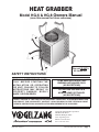
Heat GRABBer
Model HG-6 & HG-8 Owners Manual
(save this manual for future reference)
This unit is not a
UL Listed unit.
SAFETY INSTRUCTIONS
READ ALL INSTRUCTIONS CARE–
F U L LY B E F O R E S TA RT I N G T H E
I N S TA L L AT I O N O R O P E R AT I N G
THE unit. Failure to follow
instructions may result in
property da m age , bodily
injury, or even death.
To be used with SOLID FUEL
burning appliances only.
(No Exceptions)
Do NOT use this unit in a
mobile home or trailer.
(NO EXCEPTIONS)
Safety Notice: If this unit is not properly installed, a house/building fire
may result. For your safety, contact local building or fire officials about
permits, restrictions, and installation requirements for your area.
Vogelzang International Corporation
400 West 17th Street
Holland, Michigan 49423
www.vogelzang.com
Phone:1-616-396-1911
Fax: 1-616-396-1971
VGZ-017 / 0707.0
HG-6 & HG-8 Heat Grabber / Page
SAFETY INSTRUCTIONS
Read All Instructions carefully.
1. The installation of this unit must comply with
your local building code rulings. Please observe the clearances to combustibles (fig. 2).
2. Do not install this unit in a mobile home or
trailer (NO EXCEPTIONS).
3. Always connect this unit to a chimney and vent
to the outside. Never vent to another room or
inside a building.
4. Do NOT connect this unit to an aluminum
Type B gas vent. This is not safe.
5. CAUTION: Do not install the Heat
Grabber in a horizontal position.
6. The paint used on your Heat Grabber may give
off smoke and/or odor during the first fires.
This may occur during the first dozen fires
until the paint has cured. This will end and not
reoccur after paint has cured. Persons with lung
conditions or owners of susceptible domestic
pets (such as birds) should take prudent precautions. Open windows and doors as needed to
clear smoke and odor.
7. Be sure that your chimney is safely constructed
and in good repair. Have the chimney inspected
by the fire department or a qualified inspector. Your insurance company may be able to
recommend a qualified inspector.
8. Creosote or soot may build up in the chimney
connector and chimney and cause a house/
building fire. Inspect this unit, the chimney
connector, and chimney twice monthly during
the heating season and clean if necessary (see
Maintenance & Service Hints, page 5 .)
9. Do not install the Heat Grabber on a stove,
heater, or fireplace pipe that has poor draft or
“smokes.” The Heat Grabber will aggravate
this condition. Correct the draft situation
BEFORE installing.
10.Do not use a Heat Grabber that has a smaller
diameter than the flue outlet on your stove,
heater, or fireplace.
11.Do not connect duct work to the Heat Grabber. Do not restrict the air movement inside or
through the Heat Grabber.
12.Do not install on a stove, heater, or fireplace
with an operating temperature of less than 350
degrees Fahrenheit.
13.Do not install the Heat Grabber closer than 12”
to any combustible object or material. Maintain
all clearance requirements of the heating appliance (see the appliance’s owner’s manual.)
Page / HG-6 & HG-8 Heat Grabber
14.Use at least three (3) sheet metal screws at each
connection to secure the Heat Grabber to the
flue pipe.
15.While in operation, keep the soot remover
scraper knob pulled out at least 5 inches from
the front of the unit.
16.Do not touch the Heat Grabber while it
and the heating appliance is in operation. The
surfaces are hot and can cause severe burns.
Keep children, clothing, and combustible
materials away from the unit.
17.Do not allow the power cord to touch any hot
surfaces. Keep the power cord at least 12” away
from the flue pipe.
18.Use only with a grounded electrical socket.
Consult a qualified licensed electrician to provide a properly grounded socket. Do not modify
the electrical plug in any way. Dangerous or
damaging conditions could result. Do not plug
into an electrical outlet that is not grounded
or that is operated by a wall mounted on/off
switch.
19.The Heat Grabber MUST be plugged
into an electrical outlet whenever the
stove is in use. Failure to do so will likely
result in damage to the electrical components
of the Heat Grabber and could result in shock
or electrical fire.
20.Keep the unit plugged in at all times. Do Not
operate the stove if the Heat Grabber is inoperative. Doing so will damage the electrical
components.
NOTE: A professional, licensed heating
and cooling contractor should be
consulted if you have questions
regarding the installation.
CAUTION: SHOCK HAZARD
•Always disconnect plug from electrical source before adjusting or
attempting repairs.
• Always disconnect plug by grasping plug body – Do
not pull on cord to
disconnect from
wall outlet.
Figure 1
..
• Use only with properly grounded outlet. Do not alter
plug.
VGZ-017 / 0707.0
Installation Instructions
Refer to diagram and parts lists at back of this
manual.
1. Check the Owner’s Manual for your stove and
do not reduce any minimum clearances which
may be listed there. Use only Type A (all-fuel)
or lined masonry chimneys to connect to your
stove. Check your local and state building
codes for proper and safe installation.
2. If you have determined your chimney to have
an inadequate draft, overcome that deficiency
before installing your Heat Grabber. Your
chimney should be capable of developing at
least 0.06 w.c. (measured in water column)
draft before installing a Heat Grabber. After
installation, the chimney should develop at
least 0.045 w.c. as measured below the Heat
Grabber. All stove pipe above or below your
Heat Grabber must be 24-gauge or heavier to
provide adequate support. Any horizontal run
of pipe must pitch upward toward the chimney
at least 1/4” per foot of horizontal run. All stove
pipe and/or elbow joints must be secured by at
least three (3) sheet-metal screws.
3. Any elbow installed below your Heat Grabber
should be of the non-adjustable type.
4. If your stove requires a hand damper (wood
and coal stoves), install BELOW the Heat
Grabber.
5. Note: The power cord must not contact any
part of the stove, chimney connector(s) or the
Heat Grabber components. Secure the power
cord to keep it away from hot surfaces or their
proximity.
6. The Heat Grabber pipe size must be the same
or larger diameter than the flue outlet of the
heating appliance.
7. All electric supply cord connections shall
comply with the requirements of local authorities having jurisdiction over such matters.
8. Overfiring this unit is not recommended.
Refer to your heating appliance owner’s
manual regarding overfiring.
9. The Heat Grabber must be installed in your
flue pipe vertically. It may be installed with
the crimped end either up or down, according
to your installation needs.
10.The Heat Grabber should be installed as close
to the flue outlet as possible, but no closer than
15” from the top or back as shown in figure
2.
11.Do Not install the Heat Grabber closer than
18” from any combustible material.
12.Use at least three (3) sheet metal screws at
each connection to secure the Heat Grabber to
the flue pipe.
13.Keep the power cord at least 12” away from
the flue pipe.
NOTICE: In case of a power outage, your stove
may be kept in use with low heat fires provided you
remove the rear panel of the Heat Grabber (fan and
electrical components).
Figure 2
VGZ-017 / 0707.0
HG-6 & HG-8 Heat Grabber / Page
Operating Instructions
WARNING: Explosion Hazard
• Never use chemicals, gasoline,
gasoline - type lantern fuel ,
kerosene, charcoal lighter fluid,
or similar flammable liquids to
start or “freshen-up” a fire in any
heating appliance.
NOTICE: Before first use, review the
safety precautions and installation
instructions to ensure that all of
the procedures and steps have been
properly completed.
• K eep all fla m m able li q uids ,
especially gasoline, out of the
vicinity of any heating appliance
— whether in use or in storage.
Build a small fire in your stove and gradually
build up to normal operating condition. Some
smoke and odor may be evident during initial
operation. This will cease as the paint bakes
and cures.
The Heat Grabber is designed to be automatic and will turn on when the flue pipe reaches
the factory set temperature. It will also turn off
automatically when the flue temperature falls
below the factory set temperature. A toggle switch
on the rear of the Heat Grabber allows the fan to operate before the thermostat activates. Do not attempt
to alter the thermostat in any way. This not only
a convenience feature, but an important safety
device as well. Keep the electrical cord plugged
into a live circuit at all times except during
servicing to prevent overheating and possible
damage and/or malfunctioning of the unit.
Do not connect this unit to a switched circuit.
CAUTION: HOUSE FIRE HAZARDS
• F loorprotector m ust extend
underneath Heat Grabber.
• Overfiring may cause a house fire.
you are overfiring If the heater,
chi m ney connector , or H eat
Grabber glows red. Overfiring
may damage the tubing air seals
in the heat reclaimer and cause
unsafe operating conditions.
Operating Safety Precautions
1. N e v er build extre m ely large
fires in your stove as damage to the
appliance or smoke leakage may
result.
2. H eat G rabber and heating
appliances are H OT w hile in
operation. Keep children, clothing,
and Furniture away. Contact may
cause skin burns. Do not touch the
heat reclaimer or appliance after
firing until it has cooled.
3. I nspect sto v epipe and heat
exchanger tubes every 60 days.
Replace immediately if stovepipe
or tubes are rusting or leaking
smoke into the room.
CAUTION : Slow burning fires and
extended use m ay cause exces sive creosote buildup. Ignition of
creosote buildup or overfiring
may cause a chimney fire. Chimney
fires burn extremely hot and may
ignite surrounding materials. In
case of a chimney fire call the fire
department immediately.
CAUTION: Soot scraper knob and connecting rod are hot during operation
and could cause severe burns. Use
protective equipment when operating
or wait until unit has cooled before
operating.
After each firing, operate the soot scraper
(pull knob in and out) to clean the heat exchanger
tubes.
Keep soot scraper knob pulled out at least
5 inches from the face of the unit while in
operation.
Page / HG-6 & HG-8 Heat Grabber
VGZ-017 / 0707.0
Maintenance & Service Hints
Cleaning – Periodic cleaning of the Heat
Grabber is recommended. Inspect and clean at least
three times during the heating season. Remove the
unit and clean any ash or creosote from the pipes.
Vacuum or blow any dirt that has accumulated in
the outer housings of the Heat Grabber.
Fan Motor – Unsrew the rear panel.
Remove any accumulations of dirt or dust and
apply two drops of 20 weight motor oil into each
lubricating hole.
Reassemble the unit following the diagram in
the back of this manual.
Chimney Draft – Draft is a function of the
chimney, not the heating appliance. Smoke spillage
into the house or excessive buildup of condensation or creosote in the chimney are warnings that
the chimney is NOT functioning properly. Correct
the problem before using the heating appliance or
installing the Heat Grabber. Following are some
possible causes for improper draft.
1. The connector stovepipe may be pushed
into the chimney too far, stopping the draft.
2. If the chimney temperature is too cool,
water will condense in the chimney and run back
into the appliance. Creosote formation will be rapid
and may block the chimney. Operate the appliance
at a fire level high enough to keep the chimney
warm to prevent condensation from forming.
3. If the fire burns well but sometimes creates
excess smoke or burns slowly, it may be caused by
the chimney top being lower than another part of
the house or a nearby tree. The wind blowing over
a house or tree, falls on top of the chimney like
water over a dam, beating down the smoke. The
top of the chimney should be at least three (3) feet
above the roof and be at least two (2) feet higher
than any point of the roof within ten (10) feet.
VGZ-017 / 0707.0
CREOSOTE – Formation and Removal.
Slow-burning wood produces tar and other organic
vapors which combine with expelled moisture to
form creosote. Creosote vapors condense in the
relatively cool chimney flue of a slow-burning
fire. As a result, creosote residue accumulates on
the flue lining. If ignited, this creosote creates an
extremely hot fire which may ignite surrounding
materials resulting in a building fire.
If creosote has accumulated, it should be
removed. Failure to remove creosote may result
in ignition and may cause a house/building fire.
Creosote may be removed using a chimney brush
or other commonly available materials from your
local hardware retailer. Remove the Heat
Reclaimer before cleaning the chimney or
flue pipe.
Chimney Inspections – The chimney
connector and chimney should be inspected at the
beginning of and at least twice a month during the heating season to determine if a creosote
buildup has occurred.
Chimney fires burn very hot. If the chimney
connectors or the Heat Grabber should glow red,
reduce the fire by closing the damper and the appliance draft control and immediately call the fire
department.
CAUTION: A chimney fire may cause
ignition of wall studs or rafters
which were assumed to be a safe distance from the chimney. If a chimney
fire has occurred, have your chimney inspected by a qualified expert
before using again.
A fire in your heating appliance may be
smothered by pouring a large quantity of coarse
salt, baking soda, or cool ashes on top of the
fire.
HG-6 & HG-8 Heat Grabber / Page
Ordering Parts - HG6 & HG8 Heat Grabber
When ordering missing or replacement parts, always give the Model Number of the unit, Part
Number, and Part Description. Use the illustration and parts list provided to identify parts.
Top Rear View
Bottom Front View
art No.
P
1 2 3 4 5 6 7 8 9 10 11 12 13 14 DescriptionQty.
Nickle Trim.................................................... 1
Heat Exchanger Assembly........................... 1
Blade, Fan.................................................... 1
Motor, Fan..................................................... 1
Motor Capacitor (not shown)........................ 1
Cord, Power Supply...................................... 1
Rear Panel.................................................... 1
Motor Bracket............................................... 1
Thermostat Wires......................................... 2
Thermostat .................................................. 2
Outside Case................................................ 1
Bushing, Strain Relief .................................. 1
Junction Box Cover....................................... 1
Toggle Switch............................................... 1
Knob, Scraper............................................... 1
NOTE: Designate Model (HG6 or HG8) when ordering parts
Page / HG-6 & HG-8 Heat Grabber
VGZ-017 / 0707.0
Electrical Diagram - HG6 & HG8 Heat Grabber
When ordering missing or replacement parts, always give the Model Number of the unit, Part
Number, and Part Description. Use the illustration and parts list provided to identify parts.
115Vac Cord
Toggle Switch
Red
Red
black
white
Green
Snap Disk Sensor
Motor Fan Assembly
black
white
VGZ-017 / 0707.0
HG-6 & HG-8 Heat Grabber / Page
This Vogelzang heating appliance is safe when installed properly and will provide you with years of
service. However, always exercise good judgement when you are using this stove. You are dealing with
FIRE! Fire is inherently dangerous and must be treated with respect. Stay warm and in good health!
Respectfully yours,
Steve Vogelzang
Proprietor
Company Testimony:
“For God so loved the world that he gave his only begotten Son, that whoever
believes in Him shall not perish but have eternal life”
John 3:16
MADE IN CHINA
Vogelzang International Corporation
400 West 17th Street
Holland, Michigan 49423
www.vogelzang.com
Phone: 1-616-396-1911
Fax: 1-616-396-1971
Page / HG-6 & HG-8 Heat Grabber
VGZ-017 / 0707.0