1
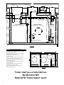
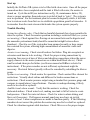
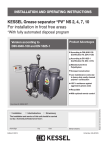
NR Series Wastewater Treatment Systems Installation & Owner’s Manual Class I Wastewater Treatment Systems 500/550/600/800/1000/1500 Gallon Per Day Capacity Commercial and Residential Systems The Environmentally Friendly Alternative for Wastewater Treatment ENVIRO-FLO Inc. P.O. Box 321161 Flowood, MS 39232 1-877-836-8476 This product has been tested in accordance with the criteria set forth in the ANSI/NSF Standards 40 & 245. PROCESS DESCRIPTION The NuWater NR Wastewater Treatment System is designed for treating domestic wastewater generated by normal household activities. The system consists of a single tank utilizing the extended aeration activated sludge process. The system is capable of producing an effluent which meets or exceeds applicable state discharge standards. This system has been successfully tested in accordance with National Sanitation Foundation (NSF) Standards 245 and 40. Treatment begins when wastewater from the home flows into the pretreatment zone of the system. Here, the organisms begin to break down and convert the waste into gases and additional microbes. This is also where nitrate is converted to nitrogen gas. The partially broken down waste then enters the treatment area, or aeration chamber. In the treatment area, waste is continually exposed to microbes for the remainder of the treatment process. The digestion action of the aerobic microbes results in a lower concentration of pathogenic bacteria. After average retention time in the aeration zone of 24 hours or more, the mixture enters the clarifier where calm conditions enable separation of microbes, solids, and treated wastewater. The microbes that settle out of the water sweep back into the aeration chamber where they are again beneficial in wastewater treatment. The proprietary airlift provides for a portion of the treated wastewater to be returned to the pre-treatment zone for additional treatment and de-nitrification. The result of aeration and quiescent separation, followed by recirculation is an effluent that is clear, odorless, and low in nutrients which may be discharged according to local health regulations. The NuWater NR Wastewater treatment system is available in concrete and polyethylene. Materials are subject to state approval. 2 NuWater NR Individual Home Wastewater Treatment System The NuWater NR system is uniquely designed based on modern concepts. This system has been tested at an ANSI certified lab. It has undergone strenuous testing, meeting ANSI/NSF standards 40 and 245 requirements, and is approved for use throughout the United States. NuWater NR Model Sizes approved by the test facility are: 500, 550, 600, 800, 1000, and 1500 GPD. Please note that all sizes may not be available due to precaster availability. The NuWater NR system consists of three compartments. They are: Pre-treatment Compartment Aeration Compartment Clarification Compartment Pretreatment Compartment In the pretreatment compartment large solids are separated out from the incoming wastewater. This compartment helps to prevent unapproved items from entering the aeration compartment. This is also where re-circulated water, from the clarifier, is returned to continue the nutrient reduction process. Aeration Compartment The aeration compartment is designed to set the right environment for aerobic microbes to grow by having air pumped in with a specific formation. The air is diffused into microscopic bubbles by low pressure diffusers. This process agitates and mixes the effluent, while promoting the growth of aerobic microbes which breakdown organic solids in wastewater. Clarifier Compartment Wastewater from the aeration chamber seeps into the clarifier from the bottom of the tank. In this system the clarifier is referred to as the still zone. In the clarifier there are no mixing of solids and wastewater. Solids are settled and diverted from the clarifier and returned to the aerator chamber for further treatment. Water, after separation, passes through a clarifier tee assembly and discharged as local laws allow. Settled solids, and a portion of treated wastewater along with microbes are re-circulated back to the pretreatment chamber. 3 9'-2 " W AT ERT IG HT RI SE RS (T YP ) LI D VEN T (t yp) 36 " MAX . DU AL PO RT AE RAT OR 1" P VC (T YP ) MAS T IC 4" 2" COU PL IN G & R E DU C ER 1/2" PV C A IR LIN E 6" 2" T E E 1" PV C S LU D GE R ET U RN LINE 12 " 2" PV C TRAS H CHAMBER CLARIFIE R CHAMBE R DIGE STE R CHAMBER O PER AT I NG CAP ACI T Y : 463 GA LLON S F LO OD C APA CI T Y: 506 G ALLO NS O PER AT I NG CAP ACI T Y : 474 GA LLON S F LOO D CA PAC IT Y: 518 G ALLO NS 160 G ALLO NS F LO O D: 191 G AL. 65 " 54 " 53 " 36 " 1" X 1/2" T EE 12 " DI F F USE R BAR S (2) PA RALE L T O T A NK W ALL 3" 4" S LU DGE R E T U R N 1. 5" T A PER S ID E V IEW INS TALLATION INS TRUCTIONS 1) Exc avate tank ho le wi th ve rti cal wa ll s to 1 fo ot l arger th an tank on a ll si des . 2) If bottom of h ol e is s to ny, i ns ta ll 3" o f co mpac t sa nd & l eve l ou t with sc re ed. 3) In stal l tank i n cen te r of hol e, keep in g 1 ft. vo id sp ace o n al l si de s. 4) As tan k i s fil l in g wi th wa te r, fi l l voi d sp ace wi th gran ul ar (sa ndy) soi l free of la rg e cl umps . 5) In stal l rest of s ystem, & affi x ri se rs to ad apters with waterproof adh esi ve. 6) Pe rform wa te rti ghtne ss test in fi el d as requ ired by l oca l j uris di ctio n. 7) Up on ap proval to b ackfi ll , c areful ly ba ckfil l with na ti ve so il s ove r top of ta nk. 8) Fi nal grade the s urfa ce to avoi d ch ane ll i ng su rfac e wa te r toward ta nk. 9'-2 " 24" BLO W ER HO US IN G CA ST ON T OP O F LI D 24 " R IS E RS (T Y P) 4'-8 " 12 " R IS E R TR A S H C H A M B E R D IG E S T E R CLAR IFIER TOP V IE W Tank Installation Detail TANK INSTALLATION DETAIL FOR NuWater ENVIRO-ROBIX 500 GPD NRNR TREATMENT UNIT 500 GPD Treatment Unit 4 5 Plant Installation Instructions Installation of the Treatment Tank (see tank drawing in appendix) Review permit / design conditions accordingly, and decide on an appropriate location for the tank(s) which is accessible to the home sewer outlet. Excavate a site which is approximately 1’ larger than the tanks at a depth that will allow proper coverage of the system. The building sewer outlet will determine the minimum depth of the plant. Make sure you have a smooth level surface for the base of the unit. The tank must be placed on stone-free undisturbed soil or fill sand / pea gravel over stony soil (stones greater than 1/2 “diameter). Place the treatment tank into the excavated site and double check for level. Carefully backfill around the unit, gently compacting the soil as well as possible, and leaving the inlet and outlet holes open for connections. Connect the influent end to the building sewer outlet. Connect the appropriate discharge to the effluent end of the plant. Only 4” schedule 40 pipes or equivalent per code should enter and exit the unit until undisturbed soil is reached. Inlet and outlet pipes should extend at least 3” into the system, with a baffle on inlet as well as (double-tee) baffle assembly on outlet. Carefully install treatment unit components (next section), then install electrical components in accordance with local electrical codes. Fill the unit to the level of the effluent discharge. One by one, turn on each electrical component and verify that there are no leaks, air or water, throughout the system. If a leak is detected, repair and retest. After all required health department and electrical inspections, carefully backfill the excavated site. The first 4” of backfill around and on top of the tank is to be the same as the backfill under the tank. Visually inspect all above ground connections, and double check riser perforations for sign of misplaced boot seals, etc. Connect the clarifier tee to the effluent pipe inside the unit making sure it is in the level vertical position. Install riser vent or vented lid at the digester access riser, or as an alternative, vent at clarifier access if tank is properly constructed with freemoving air between digester & clarifier. Data Plates The following data plates should be located on the aerator and audio/visual alarm: Remove top & filter Wash every six months or as needed NuWater Sewage Treatment 115 Volt, 60HZ, 25 Watt, 500 Class 1 For Service Call 1-877-836-8476 Model B-500NR SERIAL BNR-XXXX 6 Installation of Components (see assembly drawing in appendix) Read the equipment parts list provided in the owner’s manual and verify that all required parts are on site. Before the system package is installed inside of the unit, each component should be carefully inspected for damage or defects. Never install damaged components inside of the treatment system. The dual port linear blower should be no more than 50’ away from the plant and in a well ventilated area. The precaster will typically install a tank adapter ring onto the lid of the tank, which works well if there is 12” or more of riser height available to accommodate the blower. If the tank is shallower, blower can be installed at remote location (either in separate ventilated basin or crawlspace, etc.). Air line to diffusers should be made with 1” PVC schedule 40 pipe. Make sure the pipe is stable and resting on the excavated surface as opposed to hanging. All PVC glue fittings should be connected using approved PVC primer and cement. Use provided adapter fittings to adapt from blower to 1” PVC, as outlined in assembly drawing. A hole saw will be necessary to tap through the riser(s), and rubber grommets (recommend pull thru grommets) will be necessary to keep riser perforations watertight. As per the assembly diagram, the diffuser manifold assembly will hold the diffusers off the bottom of the tank approximately 4 inches. The screw-in diffusers are placed parallel to and approximately 4” away from the intercompartmental wall. Verify that the clarifier tee assembly is vertical and level for correct operation. The second aerator port marked “skimmer” will adapt to ½” Schedule 40 PVC as per the assembly diagram. This line feeds the airlift for the sludge recirculation. The 1” PVC recirculation inlet is installed vertically in the inlet of the clarifier, 4” from the angled hopper floor as measured from the lowest measurable point. Tie the ½” skimmer airline into the 1” x ½” tee exactly 8 inches above the recirculation inlet. The recirculation line then runs vertically up to a point as shown on the tank diagram above the liquid level, it then runs horizontally back across the digester to the pretreatment tank. Upon entering the pretreatment tank, immediately adapt up to 2” Schedule 40 PVC with the provided adaptor (this is necessary to avoid splashing at the return inlet). Run the 2” PVC back to a point visible from the access riser above, and into the 2” San-Tee provided. Extend the 2” PVC down into the pretreatment tank as shown on the tank diagram. The Aerator and alarm control panel should be installed in areas where their function will not be hindered. 7 Installation of low air alarm (see assembly drawing) The low air alarm is built into the standard NuWater ATU combo timed dosing panel. The small diameter flex air tubing attaches to the barbed brass tank tap on the side of the blower, and adapts up to ½ PVC with the provided fittings (see assembly diagram). The ½” PVC runs underground to the location of the ATU combo panel, then elbows up and transitions to UV rated (gray conduit) ½” PVC, which runs up to the base of the control panel. The provided fittings adapt back to the small diameter flex tubing at the base of the control panel. Apply a ring of silicone sealant at the perforation. The fittings will effectively pinch the bottom wall of the control panel, forming a water-tight seal, as shown on the assembly diagram. The flex tubing should do a ¾ loop inside the panel to allow slack for future removal and repositioning, and tie in at the barbed air switch. Wiring Separate circuit is required for the controls. Timer controller at panel controls effluent pump on/off. See wiring diagram. Outdoor plug receptacle independent of controls required in blower housing, resulting in constant power to blower (blower has internal controller for skim cycle). All electrical wiring shall conform to the requirements of the NEC (National Electric Code) and all other standards under the jurisdiction of the state. All external wiring must be installed in approved conduit. Salcor UV light for fecal reduction (Where required) For systems requiring fecal reduction UV disinfection is necessary. The Salcor 3G UV light is commercially available and is the disinfection unit of choice. Refer to installation instructions provided by Salcor. It is imperative that care be taken not to break the fragile UV bulb. The UV assembly shall be installed in the inlet of the pump chamber. Use a reducing fernco to suspend the UV assembly from the 6” inlet access, and install the ballast and controls just below final grade in a Electrical-style access box (similar to a valve box only larger). Individual circumstances may prevent installation inside the pump chamber, in which case the UV assembly can be direct-buried along the line between the treatment unit and the pump chamber. The base must bear on native soil or on compacted granular fill. 8 Start up Initially the NuWater NR system is to be filled with clean water. Once all the proper connections have been completed and the tank is filled with water, the aerator is turned on. Cycle the airlift (see instructions on Pg. 10, maintenance duties, #9), observe proper operation, then make sure to switch it back to “auto”. The system is now in operation. For the treatment plant to become biologically stable, it will take four to sixteen weeks from first use to establish a population growth of microbes. It is microbes from the waste stream which make the system operate properly. Trouble Shooting System has offensive odor: Check that no harmful chemicals have been permitted to enter the system. Check for aerator operation including a restricted filter (see system not aerating.) Check against free-flowing air movement between the digester and the anaerobic pretreatment tank (should be somewhat airtight between these chambers). Check to see if the system has been pumped recently or large surges have entered the system, allowing high concentrations of anaerobic waste into digester. Aerator is not running: Check circuit breakers for failure. Plug into receptacle or extension cord known to be working. Check for proper wiring connections by removing four screws at base of blower and checking connections where the power supply connects to the motor (connectors are within small black sleeve). Check small overload shear pin for failure (see blower manual or HiBlow website for instructions). If the prior remedies are not sufficient, replacement might be necessary. Electrical failure typically will not be remedied by rebuilding the blower pump. System is not aerating: Check aerator for operation. Check aerator filter element for restrictions. Visually check airline and diffusers for broken connections or restrictions. Check aerator pressure output using a standard low pressure gauge and compare to manufacturer’s specifications. If aerator is underperforming, it likely needs to be rebuilt or replaced. Audible/visual alarm sounds: Verify that the aerator is working. Check for dislocated airlines. Check water level, making sure tank is full of water to create backpressure. Check for water in blower. Check for water in alarm tubing, and blow out if necessary. If all appears normal, panel may need new air switch. Aerator is loud: Linear compressors are made to function quietly. If the following remedies do not correct the problem the aerator may need to be rebuilt or replaced. Check for vibrations against solid structures. Check filter cover for proper torque. 9 Maintenance Requirements Ongoing maintenance contracts are required for advanced treatment. The installer of an OSSDS shall either include the first two years of maintenance with the price of the installation, or as an alternative, arrange for the maintenance to be provided by an approved 3rd party maintenance provider. This must be spelled out on installation contract. Maintenance provider shall keep records of, and submit maintenance reports to the permitting authority and the owner of the system. After the first two years, the system shall be maintained at an annual interval. Maintenance Duties: 1. Remove filter element from aerator and clean with soapy water. Dry and replace. 2. Test high water alarm and low air alarm for visual or audible warning function. 3. Check components for buildup such as ant beds or grass. Keep all vents clear of foreign materials. 4. Perform sludge measurement in trash tank. Arrange for pumping if within 12 inches of outlet (more than 24” total sludge depth). 5. Observe performance of digester, check for consistent, even rolling pattern of wastewater. 6. Perform settled solids check from digester. Have tank pumped if settled solids reach 40%. 7. Perform visual check of discharging effluent for clarity, and check for rotten egg odor, which would signify improper treatment of wastewater. 8. If system is equipped with UV light, check and replace bulb if required. 9. Test operation of sludge return by temporarily switching blower to “manual” on the unmarked switch inside the cover. Stand back from the return inlet to the trash tank, as there can be a small splash upon startup of the recirculation. Check for consistent flow intermixed with bursts of air. Be sure to switch it back to “auto” when done, and observe the digester diffusers resume their airflow. 10. Inspect remainder of disposal system per county requirements, including but not limited to: Test pump discharge rate, test alarm, inspect disposal field, flush lines if necessary, etc. 10 Specifications Designation: NuWater NR 500 gpd, single family wastewater treatment system Treatment capacity/class BOD Loading Electrical requirements Aerator Panel 500 gallons per day class 1 500 gpd 1-1.5 lbs/day 115 volts 50/60 Dual Port linear blower NuWater ATU simplex combo panel Operating Instructions Once installed, the blower will run twenty-four hours a day; the system will operate with a minimal amount of attention. To ensure proper operation and minimize maintenance, the following materials should not be permitted to enter the system: 1. Strong disinfectants or bleaches except in moderation such as cleaning and normal laundry. Be conservative. 2. Oils, grease, and chemical waste. 3. Discharge from water softeners. 4. Disposable diapers, condoms, tampons, cigarette butts, etc. 5. Items which are high in phosphates such as certain laundry detergents and dish washing soaps. Service Policy The purchase price for the system includes an initial two year service policy which includes all service calls as needed due to equipment failures or manufacturer defects. These service calls will be made by the dealer or his authorized representatives and shall include the following: 1. Servicing the aerator, including replacement or cleaning of the inlet filter if necessary. 2. The unit is to be inspected every six months during the initial two year service policy. Servicing should include a check of the aerator filter, proper air flow, inspection of all electrical components, and effluent quality. 3. Immediate notification of the owner in writing of any improper operation and remedies used. The manufacturer shall notify owner with an estimated date for correction. 11 Post Warranty A continuing service policy is available from dealers to system owners whose initial service policy is due to expire. Notify dealer for price and details. Warranty Registration It is not required to register your warranty. Representatives will be responsible for all warranty information. If you wish to register your warranty please call ENVIRO-FLO, Inc. directly, and your information will be processed. Owner’s Responsibilities It is the owner’s responsibility to operate the Enviro-Flo system to the best of their ability. To ensure proper operation the following precautions should be noted: 1. Never allow unapproved items to enter the system. 2. Do not allow nest buildup around the aerator or other components. 3. Maintain grass and shrubs around system. 4. Restrict automotive travel over treatment system. Periods of Non-Use The NuWater NR has been tested for short periods of non-use, but aerobic treatment units require organic matter to be introduced periodically to function properly. If circumstances occur where the unit will not be used for long periods of time, bioremediation is recommended to seed the system before functional use begins again. Please consult your representative for proper procedures. If the system is to be transferred to new owners it is recommended that the system be completely pumped and cleaned. 12 Contact Information If service is required it is advisable to contact your nearest NuWater representative. If service is unavailable refer to the system data plates located on the aerator, audio/visual alarm, and under the system access port for contact information. The data plates contain manufacture information including telephone numbers and address. Have your model number and serial number on hand at the time of your call. The serial and model number can also be located on the data plates. NuWater NR Components While all components are durable, it is recommended that care be used when unpacking the components. Always open box in an upright position to avoid dumping of components. Visually inspect all components for breakage and notify ENVIRO-FLO Inc. for replacements if damage is present. Never install damaged components! A Word of Thanks Once again ENVIRO-FLO Inc. would like to extend a word of thanks for your recent purchase. It is our hopes that our product will provide you with many years of satisfactory service. You have helped us take one more step towards a cleaner environment and waste free waters. At Enviro-Flo, Inc. we will continue to work hard for you and strive to make business an enjoyable experience. Thanks and God bless. “For God so loved the world that he gave his only begotten son that whosoever believeth in Him shall not perish, but have everlasting life.” JOHN 3:16 13 Limited Warranty ENVIRO-FLO, Inc. warrants the parts in each treatment process/system to be free from defects in material and workmanship for a period of two (2) years from the date of installation treating residential wastewater. Some states do not allow limitations on how long an implied warranty lasts, so the above limitation may not apply. Sole obligation under this warranty is as follows: ENVIRO-FLO, Inc. shall fulfill this warranty by repairing or exchanging any component F.O.B. factory, that in ENVIRO-FLO, Inc.’s judgment shows evidence of defects, provided said component has been paid for and is returned through an authorized dealer, transportation prepaid. The warrantee must also specify the nature of the defect to the manufacturer. The warranty does not cover treatment process/system that have been flooded, by external means, or that have been disassembled by unauthorized persons, improperly installed, subjected to external damage, or damage due to altered or improper wiring or overload protection. This warranty applies only to treatment process/system and does not include any residential wiring, plumbing, drainage, or disposal system. ENVIRO-FLO, Inc. is not responsible for any delay or damage caused by defective components or materials, for loss incurred because of interruption of service, or for any other special consequential damages or incidental expenses arising from the manufacture, sale, or use of this process/system. ENVIRO-FLO, Inc. reserves the right to revise, change, or modify the construction and design of the treatment process/system for residential wastewater or any component or parts thereof without incurring any obligation to make such changes in previously sold equipment. ENVIRO-FLO, Inc. also reserves the right, in making replacements of components under this warranty, to furnish a component which, in its judgment, is equivalent to the part replaced. Under no circumstances will ENVIRO-FLO, Inc. be responsible to the warrantee for any other direct or consequential damages, including but not limited to lost profits, lost income, labor charges, delays in production, and/or idle production, which result from defects in material and/or workmanship of the system. Some states do not allow the exclusion or limitation of incidental or consequential damages, so the above limitation or exclusion may not apply to you. This warranty is expressly in lieu of any other expressed or implied warranty, excluding any warranty of merchantability or fitness, and of any other obligation on the part of ENVIRO-FLO, Inc. This warranty gives you specific legal rights. You may have other rights which vary from state to state. 14 TREATMENT SYSTEM INITIAL SERVICE POLICY Our Company, ____________________________, will operate and maintain the NuWater Aerobic System located at _____________________________________________________________, (legal description only) Permit # __________________, for the period of 2 years beginning _______________ and ending _______________. This contract will provide for all required inspections, testing and service of your NuWater Aerobic Treatment System. The policy will include the following: 1. __________ inspections a year/service calls ( at least one every ________ months), for a total of ______ over the two year period including inspection, adjustment and servicing of the mechanical, electrical and other applicable component parts to ensure proper function. This includes inspecting the control panel, air pumps, air filters, diffuser operation, and replacing or repairing any component not found to be functioning correctly. 2. An effluent quality inspection consisting of a visual check for color, turbidity, scum overflow and examination for odors. A test for chlorine residual and pH will be taken and reported as necessary. 3. If any improper operation is observed, which cannot be corrected at the time of the service visit, you will be notified immediately in writing of the conditions and estimated date of correction. 4. Any additional visits, inspections or sample collections required by specific Municipalities, Water/River Authorities, County Agencies, the TCEQ or any other regulatory agency in your jurisdiction will be covered by this policy. At the conclusion of the initial service policy, the Service Provider will make available, for purchase on an annual basis, a continuing service policy to cover labor for normal inspection, maintenance and repair. According to state law, all owners of aerobic systems must maintain a factory authorized service provider for the lifetime of the system. With 48 hours of a request for service (weekends and holidays excluded), your system will be visited by the service provider listed below or their authorized agent. If there are any items which need correction and can not be immediately remedied, the service provider will inform the home owner, in writing, of the conditions and the estimated repair date. The NuWater Homeowners Manual must be strictly followed or warranties are subject to invalidation. Pumping of sludge build-up, for reasons other than due to warrantied mechanical failure, are not covered by this policy and will result in additional charges. By signing this form, both installer and Homeowner agree to the terms of this policy. By signing this form, both the installer and the Homeowner agree that the Homeowner has received a copy of the Homeowners Manual and the Installer has made a reasonable effort to explain all pertinent information to the Homeowner. Enviro-Flo, Inc. is not responsible for service, it is the SERVICE PROVIDER indicated below. HOME OWNER SERVICE PROVIDER _______________________________________ Name ______________________________________________ Name of Service Company Representative _______________________________________ Address _____________________________________________ Address _______________________________________ City _____________________________________________ City (________)__________-___________________ (________)__________-__________________________ _______________________________________ Signature of Home Owner ______________________________________________ Signature of Service Provider and License #. 15