1
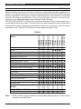
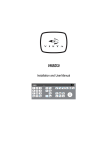
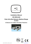
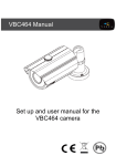
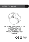
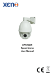
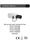
VPM8030 VPM8032 VPM8130 VPM8132 VPM8120 VPM8122 VPC9030 VPC9032 VPC9130 VPC9132 VPC9032/CM VPC9132/CM Protos 3 Series Cameras Installation Instructions Read these instructions first! Installation Instructions INTRODUCTION Read all of these instructions. Use them to install your camera and have them available for its lifetime. If you have any problems, contact your agent. Note that not all cameras have all of the features described in this manual. Refer to the table below for the features of individual cameras. All cameras are fitted with a Direct Drive (DD) lens connector, an Auto Iris (AI) connector, have adjustable back focus and accept C and CS lenses. VPC9032/CM and VPC9132/CM series cameras are designed to give a good image over a broad range of scene illumination. To achieve this, the camera operates in colour mode where the scene illumination is bright and automatically switches to monochrome where the scene illumination is low. Typically, the switchover occurs at approximately 2.0 lux. Mono Color Color/Mono Resolution (TVL) Sensitivity (lux @ f1.2) CCD Sensor size Sony SuperHAD™ CCD DSP Digital Signal Processing Adjustable Gamma (0.45 and 1.0) Automatic Gain Control (AGC) Backlight Compensation (BLC) BLC on/off Electronic Iris (EI) EI on/off Auto Iris connection Line lock with phase adjust (AC only) Internal Sync. VPC9132/CM VPC9132 VPC9130 VPC9032 VPC9030 VPM8122 VPM8120 VPM8132 VPM8130 VPM8032 VPM8030 Option VPC9032/CM TABLE 1 380 380 570 570 570 570 330 330 480 480 330 480 0.1 0.1 0.1 0.1 0.1 0.1 0.9 0.9 1.0 2.0 1.0 0.8 2.0 1.0 1/3“ 1/3“ 1/3“ 1/3“ 1/2“ 1/2“ 1/3“ 1/3“ 1/3“ 1/3“ 1/3“ 1/3“ Supply 11 - 40 VDC; 14 - 30 VAC 98 - 260 VAC Note: 2 NTSC and EIA camera models have suffixes /N and /E respectively. These variants are also covered by Table 1. Installation Instructions PRODUCT SAFETY Installation and servicing is only to be carried out by suitably qualified and experienced personnel. Mains cameras contain hazardous voltages. Do not remove covers as there is a risk of injury or death by electric shock. Cameras connected to mains supplies must be earthed. Only power low voltage cameras from a class 2 isolated power supply. This camera range is designed for use in general purpose CCTV applications and has no other purpose. Only operate your camera between the temperatures of -10OC and +50OC. Do not operate your camera outside its specified power supply range. Cameras must only be used in clean, dry, dust-free environments unless housed in suitable protective housings to IP65 or better. ELECTROMAGNETIC COMPATIBILITY (EMC) This is a class A product. In a domestic environment this product may cause radio interference in which case the user may be required to take adequate measures. This product is intended solely for use in general CCTV applications. The product must be installed and maintained in accordance with good installation practice to enable the product to function as intended and to prevent problems. Refer to Norbain SD Limited for installation guidance. MANUFACTURERS DECLARATION OF CONFORMANCE The manufacturer declares that the equipment supplied with this manual is compliant with the essential protection requirements of the EMC directive 89/336 and the Low Voltage Directive LVD 73/23 EEC. Conforming to the requirements of standards EN 55022 for emissions, IEC801 parts 2, 3 and 4 for immunity and EN 60950 for Electrical Equipment safety. 3 Installation Instructions CAUTIONS In order to avoid damaging the camera note the following points: 1) The camera has threaded mounting points on the top and bottom of the case. Only use a standard, photographic, mounting-bolt with a 1/4 20 UNC thread. 2) Before fitting the lens make sure that its back will not touch the CCD sensor or associated components when screwed fully home. 3) Do not touch the image-surface of the sensor. If the sensor is accidentally touched, only clean it using ethyl alcohol. 4) Do not expose the camera sensor to very bright light over a long period of time as this may cause damage to the CCD. The camera and lens set-up must be correct to avoid continual over exposure by bright light. 5) The weight of your camera is 0.5kg (0.35kg for low voltage versions). 6) Only use your camera in a clean, dust-free environment. 7) For outdoor use, an appropriate protective housing conforming to IP65 or UL50 or better must be used. POWER SUPPLY Cameras are available in AC mains and AC and DC low voltage types. The voltage required to operate the camera is clearly marked on the rear panel of the camera. Only power low voltage cameras from a class 2 isolated power supply. The typical power consumption of a VP... series camera is less than 5 Watts. Mains Power Supply Cameras that are intended to operate directly from the mains supply are fitted with a nondetachable power supply cord. The voltage of operation is clearly marked on the rear panel of the camera. Generally this is 98 to 260 VAC at 50 Hz for CCIR/PAL (60Hz for EIA/NTSC). REFER TO THE WIRING INSTRUCTION LABELATTACHED TO THE SUPPLY CORD and terminate the cord with the appropriate circuit fitted with a 3A fuse. MAINS CAMERAS MUST BE CONNECTED TO A PROTECTIVE EARTH GROUND. Ensure that a secure means of isolation from the mains is provided for the camera in accordance with the national wiring regulations of the country of installation. Auto-Switching Power Supply Cameras fitted with an automatic selecting power supply operate between 11-40 VDC and 14-30 VAC. Connections and polarity are indicated above the screw terminals on the rear panel. The power supply must be a class 2 isolated type. 4 Installation Instructions CONTROLS AND SWITCHES On the side of the camera is a hinged flap. The hinged flap covers various adjustment controls and function switches. 5 1 2 3 4 LOW VOLTAGE MODELS (11a) (12) MONO CAMERAS (13) 6 7 1 2 3 4 (10) (8) (9) 230 VAC MODELS (12) COLOUR CAMERAS (11b) (13) Default switch positions shown (white represents switch position) (1) Synchronisation Selection (LL/INT) This switch is used to select the camera synchronisation mode. When the camera is connected to an AC supply the Line-lock (LL) mode can be used. This locks the camera frame rate to the mains frequency so that cameras in a system are triggered at the same point on the mains AC cycle. Also see 5, 6 and 7 Line Lock Phase Adjustment. (2) Backlight Compensation (BLC) The BLC (Back Light Compensation) facility compensates for back-lit scenes by enhancing objects in the centre of the scene which would previously have been in silhouette. Select ON or OFF using the BLC switch. Default is OFF. BLC will only function with a manual iris lens when the Electronic Iris facility is switched on. For direct drive and auto iris lenses, BLC will still function even though the Electronic Iris facility is switched off. (3) Gamma Two different gamma correction options are available. Select Normal (0.45) to provide increased visibility in dark areas of the scene, or Linear (1.0). The default setting is Normal. 5 Installation Instructions CONTROLS AND SWITCHES (4) Electronic Iris (EI) The Electronic Iris (EI) compensates for excessive light level by automatically adjusting the shutter speed. The electronic iris should be ON when using fixed or manual iris lenses. When using Auto Iris (AI) lenses of either the video drive or DC drive types the EI must be OFF. Also see (10) Electronic Iris and DC Lens Level Adjustment Potentiometer. (5) Line Lock Phase Adjust Potentiometer When the camera is in line-lock mode it is possible to adjust the point on the AC cycle at which the camera triggers. This facility is provided so that cameras that are connected to different mains phases may still be synchronised. The line lock phase adjustment potentiometer allows the line lock phase trigger point to be adjusted by ±120O. Rotating the potentiometer clockwise advances the trigger point and turning it anticlockwise retards the trigger point. The factory default setting is the zero crossing point. If all cameras in a system are on the same mains phase then no line lock phase adjustment should be made. (6 and 7) Line Lock Phase Adjust Buttons (+ Advance; - Retard) When the camera is in line-lock mode it is possible to adjust the point on the AC cycle at which the camera triggers. This facility is provided so that cameras that are connected to different mains phases may still be synchronised. The line lock phase adjustment buttons allows the line lock phase trigger point to be adjusted by ±120O. Pressing the advance button advances the trigger point and pressing the retard button retards the trigger point. The factory default setting is the zero crossing point. If all cameras in a system are on the same mains phase then no line lock phase adjustment should be made. (8) Direct Drive/DC Drive Lens Connector This 4-pin connector supplies the power and DC control signal for use with DC drive Auto Iris lenses. If the lens does not have a DD plug fitted then wire the lens to a suitable plug in accordance with the diagram below: 1 2 3 4 1 = Damp 2 = Damp + 3 = Drive + 4 = Drive - DD Lens Connector (9) Back Focus Adjustment screws These two adjustment points located on the camera body top and side (top not shown), are used to adjust the back focal length or picture focus. The range of adjustment allows both C and CS mount lenses to be used without the need for a spacer ring. Refer to the section on Focus Adjustment (10) Electronic Iris and DC Lens Level Adjustment Potentiometer If the camera is used with a direct drive (DD) lens this potentiometer varies the DC reference voltage used to control the lens. The potentiometer has the effect of increasing or decreasing the lens aperture. This potentiometer should be set to obtain a 1V pk-pk video output. If a mono camera (VPM8030, VPM8032, VPM8130, VPM8132, VPM8120 and VPM8122) is used with a manual iris or fixed iris lens, and hence the electronic iris is switched ON, this potentiometer controls the electronic iris level. The potentiometer is factory set to give a 1V pk-pk video 6 Installation Instructions CONTROLS AND SWITCHES output for a typical scene. The level should not be adjusted unless absolutely necessary. (11a) Supply Voltage Terminals This terminal accepts an 11-40 VDC or 14-30 VAC at 50Hz (CCIR/PAL) or 60Hz (EIA/NTSC) power source. Ther terminals are the quick release type. To connect a cable press the appropriate release lever and insert the end of the cable fully home. Ensure that there is sufficient length of bare tinned wire to make contact with the connector. Also ensure that the cable insulation is not too thick, preventing the cable from being properly inserted. Only connect the camera to a class 2 power supply. (11b) Supply Voltage Power Cord The non-detachable power supply cord must be connected to a power supply of 98 - 260 VAC at 50Hz (CCIR/PAL) or 60Hz (EIA/NTSC). CAMERAS MUST BE CONNECTED TO A PROTECTIVE EARTH GROUND. (12) Video Iris Lens Connector This three way connector provides the power and video drive signal for use with video drive Auto Iris lenses. The terminal block that mates with this connector is provided in the packing kit. Connect the lens to the terminal block in accordance with the diagram below: + V + = Lens positive supply = Lens ground V = Video drive signal Auto Iris Lens Connections (13) Video Output BNC Connector To obtain a 1.0V [pk-pk] composite video signal, connect a video coaxial cable terminated with a 75 Ohm BNC connector to the BNC socket marked VIDEO OUT. CAMERA MOUNTING Mounting points are provided on the top and bottom of the camera and are used to mount the camera on a bracket or tripod. Only use standard, photographic 1/4 BSW (20 UNC) mounting bolts. Mounting receptacle Back focus adjustment DD lens connector 7 Installation Instructions LENS SELECTION VPC9132/CM VPC9132 VPC9130 VPC9032 VPC9030 VPM8122 VPM8120 VPM8132 VPM8130 VPM8032 VPM8030 Lens size VPC9032/CM Suitable lens types are C and CS mount in fixed iris, manual iris, auto iris or direct drive versions. Sizes are shown below. Cameras are factory set for CS mount lenses. If using a C mount lens, rotate either of the back focus screws approximately 30 turns anticlockwise before fitting the lens. 1/3" 1/2" 2/3" 1" LENS SETUP PROCEDURES For manual or fixed iris lenses set the EI switch to ON. Auto Iris Lenses Switch the EI off. Refer to the lens instructions and adjust the lens for the optimum picture (video output level of 1V peak-to-peak). Direct Drive Lenses Switch the EI off. Use an appropriate screwdriver to turn the lens level potentiometer (under the hinged flap) fully clockwise then back off until the optimum picture is obtained (video output level of 1V peak-to-peak). FOCUS ADJUSTMENT The back focus adjustment screws are located on the top and side of the case and should be adjusted using an appropriate screwdriver. If possible, always use the top screw to adjust the back focus mechanism. Turn the adjuster screw clockwise or anticlockwise to obtain focus. When the focus is sharp, turn the back focus adjustment screw 2 or 3 turns anticlockwise. The picture will lose sharpness. Turn the back focus screw clockwise until focus is once again obtained. If you have turned the back focus screw clockwise past the point of best focus, repeat the procedure. The last turn of the back focus adjustment screw must always be in a clockwise direction. Do not over turn the back focus mechanism. Fixed Lenses Set the lens focus to infinity and view an image greater than two meters away. Focus the image using the back focus screw. Set the lens focus as required. Manual Iris Lenses Open the iris fully and set the lens focus to infinity. View an image greater than 7 feet (2 meters) away. Focus the image using the back focus screw. Set the lens focus and iris as required. 8 Installation Instructions FOCUS ADJUSTMENT Auto Iris and Direct Drive Lenses Fully open the iris by covering the lens with a suitable neutral density (ND) filter. Set the lens focus to infinity. View an image greater than 7 feet (2 meters) away. Focus the image using the back focus screw. Remove the ND filter and set the lens focus as required. Zoom Lenses Set the lens focus to infinity and fully open the iris by covering the lens with a suitable neutral density (ND) filter. Zoom out to the widest field of vision and view a distant object. Adjust the back focus screw until the object is in focus. Next, zoom fully in and adjust the lenses focus until the object is again focused. Repeat these steps until the full zoom range may be viewed with the minimum loss of focus. DIMENSIONS 60 125 67 9 Installation Instructions 10 Installation Instructions 11 Norbain SDL Limited Norbain House, Eskdale Road, Winnersh Triangle, Wokingham, Berkshire RG41 5TS Norbain SDL Limited reserve the right to make changes to the product and specification of the product from time to time without prior notice HB-PROTOS3D-6 Issue 6 04/02