1
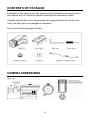
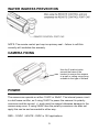
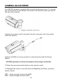
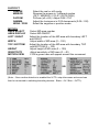
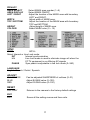
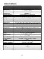
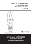
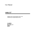
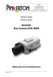
VBC464 Manual MManualManual Set up and user manual for the VBC464 camera Before You Begin Read these instructions before installing or operating this product. Note: This installation should be made by a qualified service person and should conform to local codes. This manual provides installation and operation information. To use this document, you must have the following minimum qualifications: A basic knowledge of CCTV systems and components A basic knowledge of electrical wiring and low-voltage electrical connections Intended use Only use this product for its designated purpose; refer to the product specification and user documentation. Customer Support For assistance in installing, operating, maintaining and troubleshooting this product refer to this document and any other documentation provided. If you still have questions, please contact Norbain Technical Support and Sales: Norbain Ltd 210 Wharfedale Road, IQ Winnersh, Wokingham, Berks RG41 5TP +44 118 912 5000 Note: You should be at the equipment and ready with details before calling Technical Support. Conventions Used in this Manual Boldface or button icons highlight command entries. The following WARNING, CAUTION and Note statements identify potential hazards that can occur if the equipment is not handled properly: * WARNING: Improper use of this equipment can cause severe bodily injury or equipment damage. ** Caution: Improper use of this equipment can cause equipment damage. Note: Notes contain important information about a product or procedure. 2 RoHS Announcement All lead-free products offered by the company comply with the requirements of the European law on the Restriction of Hazardous Substances (RoHS) directive, which means our manufacture processes and products are strictly “lead-free” and without the hazardous substances cited in the directive. The crossed-out wheeled bin mark symbolizes that within the European Union the product must be collected separately at the product end-of-life. This applies to your product and any peripherals marked with this symbol. Do not dispose of these products as unsorted municipal waste. CE Mark This apparatus is manufactured to comply with the radio interference. A Declaration of Conformity in accordance with the following EU standards has been made. The manufacturer declares that the product supplied with this document is compliant the provisions of the EMC Directive 2004/108/ EC, the CE Marking Directive 93/68 EEC and all associated amendments. * This symbol indicates electrical warnings and cautions. ** This symbol indicates general warnings and cautions. NORBAIN SD LTD reserves the right to make changes to the product and specification of the product from time to time without prior notice. WARNING To reduce the risk of fire or electric shock, do not insert any metallic objects through the ventilation grills or other openings on the equipment. CAUTION CAUTION RISK OF ELECTRIC SHOCK DO NOT OPEN WARNING: TO REDUCE THE RISK OF ELECTRIC SHOCK, DO NOT REMOVE COVER (OR BACK). NO USER-SERVICABLE PARTS INSIDE. REFER SERVICING TO QUALIFIED SERVICE PERSONNEL. 3 IMPORTANT SAFEGUARDS 1. READ AND RETAIN INSTRUCTIONS Read the instruction manual before operating the equipment. Retain the manual for future reference. 2. CLEANING Turn the unit off and unplug from the power outlet before cleaning. Use a damp cloth for cleaning. Do not use harsh cleansers or aerosol cleaners. 3. ATTACHMENTS Do not use attachments unless recommended by manufactured as they may affect the functionality of the unit and result in the risk of fire, electric shock or injury. 4. MOISTURE Do not use equipment near water or other liquids. 5. ACCESSORIES Equipment should be installed in a safe, stable location. Any wall or shelf mounting accessory equipment should be installed using the manufacture's Instructions. Care should be used when moving heavy equipment. Quick stops, excessive force, and uneven surfaces may cause the equipment to fall causing serious injury to persons and objects. 6. VENTILATION Openings in the equipment, if any, are provided for ventilation to ensure reliable operation of the unit and to protect if from overheating. These openings must not be blocked or covered 7. POWER SOURCES The equipment should be operated only from the type of power source indicated on the marking label. If you are not sure of the type of power supplied at the installation location, contact your dealer. For equipment designed to operate from battery power, refer to the operating instructions. 8. GROUNDING OR POLARIZATION Equipment that is powered through a polarized plug (a plug with one blade wider than the other) will fit into the power outlet only one way. This is a safety feature. If you are unable to insert the plug fully into the outlet, try reversing the plug. Do not defeat the safety purpose of the polarized plug. Alternate Warning: If the equipment is powered through a three-way groundingtype plug, a plug having a third (grounding) pin, the plug will only fit into a groundingtype power outlet. This is a safety feature. Do not defeat the safety purpose of the grounding-type plug. If your outlet does not have the grounding plug receptacle, contact your local electrician. 9. CORD AND CABLE PROTECTION Route power cords and cables in a manner to protect them from damage by being walked on or pinched by items places upon or against them. 10. LIGHTNING For protection of the equipment during a lightning storm or when it is left unattended and unused for long periods of time, unplug the unit from the wall outlet. Disconnect any antennas or cable systems that may be connected to the equipment. This will prevent damage to the equipment due to Lightning or power-line surges. 4 11. OVERLOADING Do not overload wall outlets and extension cords as this can result in a risk of fire or electric shock. 12. SERVICING Do not attempt to service the video monitor or equipment yourself as opening or removing covers may expose you to dangerous voltage or other hazards. Refer all servicing to qualified service personnel. 13. DAMAGE REQUIRING SERVICE Unplug the equipment from the wall outlet and refer servicing to qualified service personnel under the Following conditions: A. When the power supply cord or the plug has been damaged. B. If liquid has spilled or objects have fallen into the Unit. C. If the equipment has been exposed to water or other liquids. D. If the equipment does not operate normally by following the operating instructions, adjust those controls that are covered by the operating instructions as Improper adjustment for other controls may result in damage to the unit. E. If the equipment has been dropped or the casing is damaged. F. When the equipment exhibits a distinct change in performance. 14. REPLACEMENT PARTS When replacement parts are required, be sure the service technician uses replacement parts specified by the manufacturer or that have the same characteristics as the original part. Unauthorized substitutions may result in fire, electric shock, or other hazards. 15. SAFETY CHECK Upon completion of any service or repairs to the equipment, ask the service technician to perform safety checks to verify that the equipment is in proper operating condition. 16. FIELD INSTALLATION The installation of equipment should be made by a qualified service person and should conform to all local codes. 17. CAUTION - THESE SERVICING INSTRUCTIONS ARE FOR USE BY QUALIFIED SERVICE PERSONNEL ONLY. TO REDUCE THE RISK OF ELECTRIC SHOCK DO NOT PERFORM ANY SERVICING OTHER THAN THAT CONTAINED IN THE OPERATING INSTRUCTIONS UNLESS YOU ARE QUALIFIED TO DO SO. 18. Use certified/Listed Class 2 power source only CE COMPLIANCE STATEMENT WARNING This is a Class A product. In a domestic environment this product may cause radio interference in which case the user may be required to take adequate measures. 5 TABLE OF CONTENTS INTRODUCTION --------------------------------------------------------------------------------------- 7 CONTENTS OF PACKAGE / DIMENSIONS --------------------------------------------- 8 CAMERA INGRESS / FIXING / POWER --------------------------------------------------- 9 CAMERA ADJUSTMENT ------------------------------------------------------------------------- 10 OSD MENU TREE ------------------------------------------------------------------------------------- 11 SPECIFICATIONS ------------------------------------------------------------------------------------- 15 6 INTRODUCTION Camera Model Features: The camera provides high-quality images using SONY 1/3” CCD and digital Signal process LSI. Features: ● High resolution and high performance 1/3” SONY Super HAD CCD Technology. ● 580TVL (Colour), 600TVL (B/W) of resolution ● 6-50mm Varifocal lens (f1.4) ● 1.5 Lux (Colour), 0 Lux (IR LED ON) ● Auto electronic shutter [1/50 - 1/100,000] and manual electronic shutter modes ● 72 x 850nM LED’s provide illumination up to 60M ● OSD (On Screen Display) - via provided plug in joystick ● 3D-DNR (Dynamic Noise Reduction) ● D-WDR (Digital Wide Dynamic Range) ● AGC (Auto Gain Control) ● Colour & B&W switching by photocell ● Auto and manual white balance modes ● Selectable BLC zone or HSBLC (Peak White Inversion zone) ● 8no Privacy Zones ● 4no Motion Detection zones with 5vTTL output ● Mirror, D-Zoom, Nega/Posi, Sharpness, D&N, Rotation, Freeze ● Externally adjustable focus & zoom ● Cable managed bracket suitable for wall or ceiling mounting. ● IP66 weatherproof housing ● Operates on 12vDC (-10 ~ +15%) or 24VAC (+/-10%) 7.0W ● Use Certified / Listed Class 2 power source only 7 CONTENTS OF PACKAGE Installation of the camera must be performed by qualified service personnel in accordance with all local and national electrical and mechanical codes. Carefully remove the colour camera and its accessories from the carton and verify that they were not damaged in shipment. The content of the package includes: CAMERA DIMENSIONS 8 WATER INGRESS PREVENTION NOTE: The remote control port cap is a primary seal – failure to refit this correctly will invalidate the warranty. CAMERA FIXING Use the 3 location holes around the base of the bracket to secure the camera to a wall or ceiling using fixing suitable to the type of surface POWER The camera can operate on either 12vDC or 24vAC. The internal power circuit is a half wave rectifier, so if using 12vDC to power the camera it is polarity conscious and the correct +/- ports must be obeyed otherwise damage to the camera may occur. If using 24vAC then the polarity conscious rule does not apply this can be and connected to either way. RED – 12VDC / WHITE - 0VDC in 12V applications 9 CAMERA ADJUSTMENT The VBC464 camera is supplied with a remote control set up tool. To connect the remote control to the camera, first remove the Remote control port cap at the rear of the camera: Connect the remote control using the 6 pin din connector end to the socket within the camera: Connect the BNC to a set up monitor to view the picture and On Screen Menus. All OSD operation is via the tact switch on the plug in controller To Enter the menus press the button on the remote control. To Navigate the menus, move the button left/Right/Up and Down, press the button to Enter. RET – takes you back a step in the OSD END – saves changes and exits OSD 10 OSD MENU TREE <MAIN MENU> LENS EXPOSURE WHITE BALANCE DAY / NIGHT 3DNR SPECIAL ADJUST RESET EXIT <LENS> <EXPOSURE> DC SHUTTER BRIGHTNESS AGC SENSE-UP BLC D-WDR RETURN <WHITE BAL> <DAY&NIGHT> <3DNR> AWB AUTO B/W COLOUR LEVEL RETURN AWC→ MANUAL INDOOR OUTDOOR ATW <SPECIAL MENU> <ADJUST> <RESET> CAMERA TITLE D-EFFECT RS485 MOTION PRIVACY SYNC LANGUAGE RETURN SHARPNESS BLUE RED RETURN FACTORY RETURN 11 OSD Settings <LENS> DC LENS Brightness Adjust brightness level (0 ~ 100) <EXPOSURE> SHUTTER x256, x128, x64, x32, x16, x8, x4, x2, 1/50, FLK, 1/250, 1/500, 1/2000, 1/5000, 1/10000, 1/100000 (FLK – Flickerless reduces screen flickering caused by out of phase lighting frequency) AGC OFF/ LOW / MID / HIGH SENSE-UP Low-speed shutter control is defaulted to AUTO, this can be set to the following options, the larger the number the more integration is applied to the picture: OFF - AUTO x2, x4, x8, x16, x32, x64, x128, x256 (Note that this will only work when the shutter speed is set at 1/50 and AGC is set to low / mid / high) BLC OFF / BLC / HSBLC Both BLC and HSBLC have a definable 7 x 7 area (max) in the 8 x 8 grid of where to apply (One single block of segments can be set e.g. 2x1, 2x3, 4x4 etc) BLC – helps to reduce the silhouette effect when the target is against a bright background HSBLC (Peak White Inversion) – reduces high illumination (e.g. vehicle headlights) and inverts the white signal to black 12 BLC MODE GAIN DEFAULT LEFT / RIGHT WIDTH TOP / BOTTOM HEIGHT HSBLC MODE LEVEL DEFAULT LEFT / RIGHT WIDTH TOP / BOTTOM HEIGHT Low / Mid / High Restore BLC back to factory settings Adjust location on screen (0 ~ 7) Adjust size of area (0 ~ 8) Adjust location on screen (0 ~ 7) Adjust size of area (0 ~ 8) (Peak White Inversion) Brightness of light before PWI occurs (0 ~ 8) BLC back to factory settings Adjust location on screen (0 ~ 7) Adjust size of area (0 ~ 8) Adjust location on screen (0 ~ 7) Adjust size of area (0 ~ 8) D-WDR Wide Dynamic Range setting enables a widely contrasting scene of view to provide a balanced picture. OFF / INDOOR / OUTDOOR <WHITE BAL> Allows accurate reproduction of White by controlling the R.G.B. level AWB Wide range auto white balance mode. AWC->SET Please press the ENTER button while the camera is directed at a piece or while paper to obtain the optimum state under current illumination. If the environment including the light source is changed, you have to adjust the white balance again. 13 MANUAL RED GAIN BLUE GAIN Manual mode - user can change R and B Gain manually Adjust RED value (0 ~ 100) Adjust BLUE value (0 ~ 100) INDOOR OUTDOOR ATW Set the colour temperature to 3200ºK Set the colour temperature to 6300ºK Set the colour temperature 2500 ºK to 9500 ºK <DAY&NIGHT> COLOUR B/W AUTO Forces the camera into permanent colour mode Forces the camera into permanent monochrome mode Switching between Colour & monochrome images are determined by the photocell and also switches IR LEDS on and removes IR cut filter. In AUTO mode the switching points can be adjusted if required: S Level – switching from colour to mono (1~100). The higher the number the darker it needs to be before it switches over to monochrome – Lower Lux) E Level – switching from mono to colour (1~100). The lower the number the lighter it needs to be before it switches back to colour – Higher Lux) 14 B/W mode – whist set in permanent monochrome mode you can also remove the colour burst, which reduces image noise <3DNR> Reduces noise within the picture when AGC is active OFF / ON ON Adjust 3DNR level (0 ~ 100) (Note that this will only work when AGC is in LOW / MID / HIGH setting) <SPECIAL> CAM TITLE 15 character camera name/title allocation ←: Move to left →: Move to right CLR: Erase all characters. POS: Move the Position of title END: Save and End 15 D-EFFECT FREEZE MIRROR D-ZOOM GAMMA NEGA / POSI MOTION AREA SELECT AREA DISPLAY LEFT / RIGHT WIDTH TOP / BOTTOM HEIGHT SENSITIVITY MOTION VIEW Select the real or still mode Reverse the screen in 3 different modes (OFF / MIRROR / V FLIP / ROTATION) D-Zoom (x2~x32) / Adjust PAN / TILT Adjust the luminance in 0.05 decrements (0.05~1.00) Select the negative or positive mode. Select MD area number Select MD ON/OFF Adjust the location of the MD area with boundary LEFT and RIGHT Adjust width of MD area (0 ~ 100) Adjust the location of the MD area with boundary TOP and BOTTOM (0 ~ 100) Adjust height of MD area (0 ~ 100) Adjust sensitivity of MD area (0 ~ 40) If ON a green trace will appear around the movement (Note – Once motion detection is enabled the 5vTTL output becomes active and can then be connected to switching/recording devices. Black – 0V / Blue – 5VTTL) 16 PRIVACY AREA SELECT AREA DISPLAY LEFT / RIGHT WIDTH TOP / BOTTOM HEIGHT COLOUR Select MASK area number (1~8) Select MASK ON/OFF Adjust the location of the MASK area with boundary LEFT and RIGHT. Adjust width of MASK area. Adjust the location of the MASK area with boundary TOP and BOTTOM. Adjust height of MASK area. Select MASK color (0 ~ 15) SYNC SYNC INT/LL Select Internal or Line Lock mode. INT Internal synchronization L/L Line Lock mode is used to eliminate image roll when the CCTV equipment is on differing AC signals PHASE Sync phase is adjustable in line lock mode (0~360) LANGUAGE English / French / Dutch / Spanish ADJUST SHARPNESS BLUE RED Can be adjusted SHARPNESS of outlines (0~31) Adjust B-GAIN value (0~100) Adjust R-GAIN value (0~100) RESET FACTORY Returns to the camera to the factory default settings EXIT EXIT Saves all the setting menus and then exits. 17 SPECIFICATIONS Model Signal Format Image Device Effective Pixels Inter. H/V Horizontal Resolution Day/Night Lens Minimum Illumination Camera operation Gamma S/N Ratio Sync System Video Output Electronic shutter Manual shutter Sense-up AGC BLC White Balance Day&Night Motion Detection Privacy Zone 3-DNR D-WDR Image Functions OSD Languages IR LED IR LED Operation IP Rating Operating Temperature Storage Temperature Power Colour Weight (net) Weight (gross) Unit Dimensions (mm) Box Dimensions (mm) VBC464 PAL 1/3" SONY Super HAD CCD 752(H) x 582(V) 15,625KHz(H), 50Hz(V) 580TVL Colour / 600TVL Monochrome 6-50mm (f1.4) 1.5 Lux (Colour), 0 Lux (IR LED ON) OSD via plug in joystick at rear of camera r=0.05 ~ 1.0 (Adjustable) More than 50dB (AGC off) Internal / Line Lock 1.0 Vp-p Composite (75Ω) 1/50 ~ 1/100,000sec 1/50, FLK, 1/250, 1/500, 1/2000, 1/5000, 1/10,000, 1/100,000 Off / Auto (X2, X4, X8, X16, X32, X64, X128, X256) Off / Low / Middle / High OFF / BLC / HSBLC AWB/ AWC→ / MANUAL / Indoor / Outdoor / ATW Colour / BW / Auto 4no Zone (On / Off) 5vTTL output 8no Zone (On / Off) Off / On (0 ~ 100 Level Adjustable) Off / Indoor / Outdoor Freeze / Mirror / D-zoom / Sharpness / Colour gain / Gamma / NEG.Image English / Spanish / Dutch / French 72no 850nm, >60m On (Start) : 7.01Lux, Off (End) : 0.95Lux IP66 14 ~122 (-10 ~+50 ) -4 ~140 (-10 ~+60 ) 12vDC (-10~+15%) / 24AC (+/-10%) (7.0W) Pantone Black C 1160g 1575g 88 (W) x 88 (H) x 267.1 (L) including bracket 250 (W) x 200 (H) x 140 (D) 18 Norbain Ltd, 210 Wharfedale Road, IQ Winnersh, Wokingham, Berkshire. RG41 5TP United Kingdom Manual version 1.2 (this manual is subject to change without prior notice 19