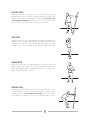
1
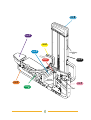
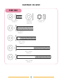
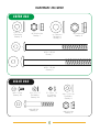
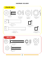
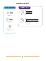
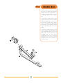
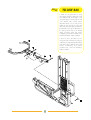
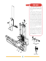
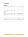
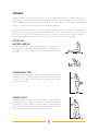
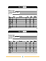
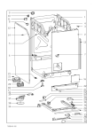
Assembly &
Owner’s Guide
ST720
MULTI-PRESS
2
Table of Contents
A S S E M B LY G U I D E
OWNER’S GUIDE
ASSEMBLY GUIDE . . . . . . . . . . . . . . . . 4
HARDWARE BAGS . . . . . . . . . . . . . . . . 6
STEP 1: ORANGE BAG . . . . . . . . . . . . 11
STEP 2: BLUE BAG . . . . . . . . . . . . . . . 12
STEP 3: PINK BAG . . . . . . . . . . . . . . . 13
STEP 4: GREEN BAG . . . . . . . . . . . . . . 14
STEP 5: BLACK BAG . . . . . . . . . . . . . . 15
STEP 6: YELLOW BAG . . . . . . . . . . . . 16
STEP 7: RED BAG . . . . . . . . . . . . . . . 17
STEP 8: LIGHT BLUE BAG . . . . . . . . . . 18
STEP 9: PURPLE BAG . . . . . . . . . . . . . 19
RESISTANCE TRAINING BENEFITS
& TIPS, WORKOUT VARIATIONS . . . . . . 20
TRAINING PROGRAMS . . . . . . . . . . . . 21
STRETCHING . . . . . . . . . . . . . . . . . . . 22
MAINTENANCE SCHEDULE . . . . . . . . . . 24
COMMERCIAL WARRANTY . . . . . . . . . . 25
WORKOUT LOGS . . . . . . . . . . . . . . . . 26
3
Assembly &
Owner’s Guide
ST720
MULTI-PRESS
To avoid possible damage to this Multi-Press, please follow these assembly steps in the correct order. Before
proceeding, find your new Multi-Press serial number located on the center floor support (AG2), and enter here:
Refer to this number when calling for service, and enter this serial number on your Warranty Card and in your
own records. Be sure to read your Owner’s Guide before using your new Multi-Press.
If any parts, hardware or tools are missing, please call 1.800.335.4348, Extension 12
NOTE: During each assembly step, ensure that ALL screws are in place and partially threaded in before completely
tightening any ONE screw.
4
STEP
STEP
9
STEP
STEP
6
2
General Warning
Decal
STEP
STEP
8
7
STEP
5
STEP
3
Pinch Point
Decal (both sides)
1
STEP
4
Serial #
5
HARDWARE INCLUDED
ORANGE BAG
10.2 x 22 x 2
Flat Washer
Quantity: 6
M10 x 20 Bolt
Quantity: 2
M10 x 70 Bolt
Quantity: 2
M10 Nylon Nut
Quantity: 2
BLUE BAG
M10 x 70 Bolt
Quantity: 4
10.2 x 22 x 2
Flat Washer
Quantity: 18
M10 x 125 Bolt
Quantity: 3
M10 x 120 Bolt
Quantity: 2
6
M10 Nylon Nut
Quantity: 9
HARDWARE INCLUDED
PINK BAG
M10 x 20 Bolt
Quantity: 2
10.2 x 22 x 2
Flat Washer
Quantity: 22
M10 x 60 Bolt
Quantity: 2
M10 x 70 Bolt
Quantity: 2
M10 x 120 Bolt
Quantity: 2
M10 x 123 Bolt
Quantity: 4
7
M10 Nylon Nut
Quantity: 10
HARDWARE INCLUDED
GREEN BAG
10.2 x 22 x 2
Flat Washer
Quantity: 2
M10 Nylon Nut
Quantity: 1
13 x 26 x 2.5
Flat Washer
Quantity: 4
M12 Nylon Nut
Quantity: 2
M10 x 140 Bolt
Quantity: 1
M12 x 152 Bolt
Quantity: 2
BLACK BAG
M5 x 10 Bolt
Quantity: 24
5.2 x 10 x 1.5
Flat Washer
Quantity: 24
5.1 x 9.3 x 1.3
Lock Washer
Quantity: 24
M8 x 62 Bolt
Quantity: 2
8.4 x 15.5 x 1.6
Flat Washer
Quantity: 4
M8 Nylon Nut
Quantity: 2
8
HARDWARE INCLUDED
YELLOW BAG
M12 x25 Bolt
Quantity: 2
12.2 x 21.5 x 3
Lock Washer
Quantity: 2
130mm Axle
illustration not to scale
Quantity: 1
20.7x 29.1 x 0.3
Wavy Washer
Quantity: 1
13 x 26 x 2.5
Flat Washer
Quantity: 2
Bushing (F10)
illustration not to scale
Quantity: 1
Bushing (D07)
illustration not to scale
Quantity: 1
200mm Axle
illustration not to scale
Quantity: 1
RED BAG
M10 x 68 Bolt
Quantity: 1
M10 Nylon Nut
Quantity: 3
M10 x 48 Bolt
Quantity: 2
9
10.2 x 22 x 2
Flat Washer
Quantity: 6
HARDWARE INCLUDED
LIGHT BLUE BAG
PURPLE BAG
M5 x 10 Bolt
Quantity: 22
M10 x 30 Bolt
Quantity: 3
M5 x 15 Bolt
Quantity: 6
M10 x 60 Bolt
Quantity: 2
Slip-On Nut
illustration not to scale
Quantity: 2
10
STEP
1
ORANGE BAG
• Slide the sliding seat bottom assembly
(AH1) onto the sliding seat support tube
(AH2), rollers first. Disengage pull pin of
seat bottom assembly until it locks into one
of the range of motion holes in the support
tube.
• Set main floor support (AC1) on the
ground, with curved end up, and place
sliding seat support tube so that holes in
the end of the floor support line up with the
holes on the sliding seat support tube.
Attach using two bolts (M10x70), four flat
washers (10.2x22x2), and two nylon nuts
(M10).
• Place the seat back support post (AT3)
over the opposite end of the sliding seat
support tube (AH2), aligning the holes in
all three frame sections. Thread two bolts
(M10x20) and two flat washers
(10.2x22x2) through top of seat back
support post. Do not place any bolts
through other holes, as it will be done in
the following step!
11
STEP
2
BLUE BAG
• Slide a bolt (M10x125) and a flat
washer (10.2x22x2) through the hole,
right of center, on the seat back support
post (AT3). Attach another flat washer
(10.2x22x2) and a nut (M10) to the back
side.
• Place the T-shaped end of center floor
support (without pulley) (AG3) up against
main floor support (AC1). Slide two bolts
(M10x120 on the outside and M10x125
on the inside of the bracket) and two flat
washers (10.2x22x2) through the holes.
Slide another flat washer (10.2x22x2)
onto each bolt and secure with two nylon
nuts (M10).
• Grab the other center floor support (with
pulley) (AG2) and slide the end without
the pulley bracket up to holes next to
where other center floor support (AG3)
was just installed. Secure using two bolts
(M10x125 on the inside and M10x120 on
the outside of the bracket), four flat washers
(10.2x22x2), and two nylon nuts (M10).
• Stand the weight stack tower (AB1)
upright and place it against both center
floor supports. Slide four bolts (M10x70)
and four flat washers (10.2x22x2)
through connecting holes, and secure
bolts with four more flat washers
(10.2x22x2) and four nylon nuts (M10).
M10x120
M10x125
M10x120
12
STEP
3
PINK BAG
• Take the swing arm support (AC3) and
insert into the end of the main floor support
tube (AC1). Align holes in both tubes.
Vertically insert and tighten two bolts
(M10x20) and two flat washers
(10.2x22x2).
• Place the swing arm pulley bracket
(AC2) over the main floor support, aligning
the holes along the intersection point of
swing arm support (AC3) and main floor
support (AC1). Secure in place using four
bolts (M10x123), eight flat washers
(10.2x22x2), and four nylon nuts (M10).
Attach the rear bracket (AC2) to the swing
arm support (AC3) by sliding two bolts
(M10x70) and two flat washers
(10.2x22x2) through and fastening two flat
washers (10.2x22x2) and two nuts (M10).
• Attach the weight stack connecting
brace (AG1) to the weight stack tower
using two bolts (M10x60), four flat washers
(10.2x22x2), and two nylon nuts(M10).
Attach other side of connecting brace to
swing arm support using two bolts
(M10x120), four flat washers (10.2x22x2),
and two nylon nuts (M10).
13
STEP
4
GREEN BAG
• Grab the seat back support (AT1) and
align the holes at the end of the tube with
the open holes in the sliding seat bottom
assembly (AH1). Connect with arrow up
using one bolt (M10x140), two flat washers
(10.2x22x2), and a nylon nut (M10). Lay
the seat back support so that it rests on
seat back support post (AT3).
• On each side of the seat back support
(AT1), attach the seat back connecting
braces (HO9) using one bolt (M12x152),
two flat washers (13x26x2.5), and one
nylon nut (M12). Attach the other side of
the connecting braces to the main floor
support (AC1) directly underneath the seat
back support post. Secure with one bolt
(M12x152), two flat washers (13x26x2.5),
and one nylon nut (M12).
Connect with
arrow up
14
STEP
5
BLACK BAG
• Secure top and bottom shield brackets
QO5) to weight stack tower (AB1) using
bolts (M5x10), flat washers (5.2x10x1.5),
and lock washers (5.1x9.3x1.3) provided.
Repeat for all side brackets (QO4).
• Place two rubber weight plate bumpers
(K10) over the holes in the lower cross tube
of the weight stack tower. With the horizontal
holes of the guide rods at the bottom, place
them over and through the rubber weight
plate bumpers into the weight stack tower.
Let the guide rods tilt outward from the
tower. Slide each of the 20 weight plates
(K02) over both of the guide rods on top of
one another. Place the header weight plate
(K01) over both guide rods on top of other
weight plates.
• Slip the rubber guide rod sleeves (K11)
over the top of the guide rods, then snap
into holes in the weight stack tower. Lift the
guide rods into top of weight stack tower
until holes in the guide rod are lined up with
the horizontal holes at the top of the weight
stack tower. Insert a bolt (M8x62) and flat
washer (8.4x15.5x1.6) through each guide
rod and fasten with a flat washer
(8.4x15.5x1.6) and a nut (M8).
15
STEP
6
YELLOW BAG
• Attach the swing arm (AF1) to swing
arm support (AC3) by guiding the small
axle (FO8) through the bracket on the
swing arm support. Once through the wall
of the bracket, slide a wavy washer
(20.7x29.1x0.3) over the axle, before
sliding the axle through the swing arm
(AF1). After exiting the opposite wall of the
bracket (make sure to line the flat surface of
the axle up with the flat on the bracket)
attach a bushing (F10), flat washer
(13x26x2.5), lock washer (12.2x21.5x3),
and bolt (M12x25). Tighten hardware.
• Place the press arm (AD1) over the
swing arm (AF1) and fasten by sliding a
shaft (DO1) through (match up flat surfaces)
and attach with a bushing (DO7), flat
washer (13x26x2.5), lock washer
(12.2x21.5x3), and bolt (M12x25).
Tighten hardware.
16
STEP
7
RED BAG
• Attach pulleys A and B to the weight
stack tower with a bolt (M10x48), a flat
washer (10.2x22x2) on each side, and a
nut (M10).
• With loop end of cable (F17) in hand,
guide it through hole in top of weight stack
tower and around pulleys A and B. Follow
the weight stack down to go around pulley
C. Loosen pulley D and make sure the
cable is routed between the pulley and the
post. Retighten. Weave the cable around
pulley E, F, and G. Terminate after placing
the loop through the bottom of the swing
arm tube, where it will be secured by sliding a 15x21.5 bushing, a bolt (M10x68),
and a flat washer (10.2x22x2) through
the hole in the swing arm and through the
loop in the cable. Secure with another bushing (15x19.5), a flat washer (10.2x22x2)
and a nylon nut (M10), after exiting the
opposite side of tube.
• Remove nut on bolt end of cable and
place the weight pin tether (K09) on bolt
shaft. Thread the nut on the bolt end of the
cable all the way to the head of the bolt.
Thread the bolt into the header plate,
making sure that there is a minimum of
0.5” of engagement. Secure by tightening
nut onto header plate.
Cable Termination
Detail
Bottom View
17
STEP
8
LIGHT BLUE BAG
• Align holes in rear shield (QO3) with
the holes in the brackets on the back side
of the weight stack; secure using 10 bolts
(M5x10). Take the left (QO1) side shield
and repeat on front side of weight stack
tower using six bolts (M5x10). Tighten
interior brackets (B09 & B10). Attach right
side shield (Q02) with six bolts (M5x10).
• Place slip-on nuts over the holes of the
left weight stack tower upright. Snap two
halves of top cover together (QO6 &
QO7). With tallest point facing the rear of
the machine, place the assembled top
covers on top of the weight stack tower
and secure using six screws (M5x15).
18
STEP
9
PURPLE BAG
• Secure seat bottom (JO1) to seat bottom
frame (AT2) using three bolts (M10x30).
• Secure seat back (JO2) to seat back
support (AT1) using two bolts (M10x60).
19
RESISTANCE TRAINING BENEFITS AND TIPS
Always consult a physician before starting an exercise program.
To be successful in your exercise program, it is important to develop an understanding of the basic principles of
resistance training. Now that you have assembled your VISION FITNESS gym, it is only natural that you want to
get started immediately. First, determine a few realistic, short term goals and expectations for yourself. Choose an
appropriate exercise routine that best suits your individual needs. Any of the 3 programs, explained in the Training
Programs section below, is a great starting point.
Warm up properly before engaging in resistance training. Stretching, yoga, jogging, calisthenics, or other cardiovascular
exercise can help prepare your body for the heavier workload of lifting weights.
Learn how to perform the exercise correctly before using heavy weight. Correct form is important to avoid injury
and ensure that you work the proper muscle groups.
Know your limitations. If you are new to resistance training or are starting back, after an extended layoff, start slowly
and build foundational strength over a longer period of time.
Pay attention to your breathing. As a general rule of thumb: inhale on the non-exertion part of the movement and
exhale during the exertion portion. Never hold your breath.
Keep in mind how important the recovery phase is in achieving your goals. The general rule is to allow a minimum
of 48-72 hours before training the same muscle/s. If you still experience soreness after this period of time has
elapsed, take a few additional days until the soreness has subsided.
Use this manual to guide you through the basic exercises you can perform on your VISION FITNESS gym. To achieve
maximum results and avoid possible injury, consult a fitness professional to formulate a complete exercise program.
WORKOUT VARIATIONS
OVERHAND OR PRONATED GRIP
NEUTRAL GRIP
UNDERHAND OR SUPINATED GRIP
20
TRAINING PROGRAMS
MUSCULAR ENDURANCE
A program that stresses moderate intensity, a lower amount of resistance, and higher repetitions (anywhere from
13-100 or more). These types of sets will take longer to complete. This type of training conditions the muscles for
activities that stress the slow twitch muscle fibers of your body. This is beneficial for sustaining energy over moderate
periods of time.
MUSCULAR STRENGTH
A program that stresses high intensity, a higher amount of resistance, and lower repetitions (anywhere from 6-12).
These types of sets will take a shorter period of time to complete. This type of training conditions the muscles for
activities that stress the fast twitch muscle fibers of the body. This is beneficial for activities that require short bursts
of speed and power.
SPRINT 8
This program is exclusive to VISION FITNESS exercise equipment. This is a program that stresses high intensity, a
moderate amount of resistance, and as many repetitions that a person can perform in a specified period of time
(usually 20-30 seconds). This program works especially well for the time crunched exerciser. It allows you to work
both the slow and fast twitch muscle fibers of the body. This program gives you a good cardiovascular and strength
workout. The thing that is most appealing about this program is that an individual can complete it in 20 minutes.
This is how the program works:
The person picks the number of exercises they want to perform. Examples would be 1, 2, 4, or 8 exercises. The
individual completes a 3 minute warm up with a brisk walk or on a piece of cardiovascular equipment. After the
warm up is complete, the user begins performing the first exercise maintaining a high intensity pace throughout the
determined amount of time (20-30 seconds). After this period of time, the individual can perform an active, low
intensity recovery phase, stretching, or complete rest. This should last 1.5-2 minutes or less, if you are at a higher
fitness level. After the recovery phase, the individual performs the second high intensity exercise for the required
amount of time (20-30 seconds). This is followed by the second recovery phase. This process repeats until you are
done with 8 high intensity intervals. Finish the workout by completing a 3-5 minute very low intensity cool down.
21
STRETCHING
Flexibility Training is not associated with fitness as often as cardiovascular exercise or Strength Training, even
though it is just as important. A good stretching program will help to maintain flexibility of the hips and lower
back. A flexible person will be less likely to injure themselves in common activities, such as reaching, twisting and
turning, or in uncommon activities such as the annual softball tournament.
Before stretching, take a few minutes to warm up the muscles because stretching a cold muscle can cause injury.
Start your stretch slowly, exhaling as you gently stretch the muscle. Try to hold each stretch 15 to 30 seconds.
Don’t bounce when you stretch. Holding a stretch offers less chance of injury. Don’t strain or push a muscle too
far. If it hurts, ease up. Here are a few stretches you can incorporate into your exercise program:
SEATED TOE TOUCH
(HAMSTRINGS & LOWER BACK)
Sit on the floor with your legs together and straight out in front of you. Do
not lock your knees. Extend your fingers toward your toes, exhaling as you
go. Hold for 15 to 30 seconds. Return to the start position, and repeat as
necessary.
STANDING QUADRICEPS STRETCH
Using a wall to provide balance, grasp your left ankle with your left hand
and hold to stretch. Your knee should be pointing toward the floor. Hold
the stretch for 15 to 30 seconds. Repeat with your right leg, and continue
to alternate as necessary.
STANDING CALF STRETCH
Standing about three to four feet from the wall, take one step forward with
your right foot. Place your hands on the wall in front of you. Bend your right
leg slowly, using your movement to control the amount of stretch in the left
calf. Your left heel should remain on the ground. Slowly bring yourself back
to the starting position and switch legs. Repeat as necessary.
22
BICEP/CHEST STRETCH
Grasp an immovable object (pole or corner of a wall) with your feet
planted firmly and evenly on the floor. With the palm of your stretched side
facing forward, rotate your hips away from that hand. Be careful not to rotate
too far or hyperextend the elbow joint. Hold the stretch for 15 to 30 seconds. Repeat
with the opposite side, and continue to alternate as necessary.
TRICEP STRETCH
Stand erect with your eyes fixated straight ahead. Raise and bend your
right arm until your forearm is parallel to the floor (palm down). Grasp the
area below the right elbow with your left hand. Gently apply a constant
upward force for 15 to 30 seconds. Switch arms and repeat as necessary.
SHOULDER STRETCH
Make sure your feet are even and planted firmly on the floor. Grasp your
right arm, behind the elbow, with your left hand. While keeping both
elbows bent, apply a gentle, constant pull to the left for 15 to 30 seconds.
Switch arms and repeat as necessary.
UPPER BACK STRETCH
Stand facing an immovable object, feet even and flat on the floor. Grasp
the object (fingers interlocked or one hand over the other) and slowly move
your hips to the rear. Be very careful not to round your back. Only stretch as far as
your comfort zone. Hold for 15 to 30 seconds and repeat as necessary.
23
MAINTENANCE SCHEDULE
FOR BEST PERFORMANCE WE RECOMMEND THE FOLLOWING MAINTENANCE SCHEDULE:
Check the integrity and function of the following parts. Replace all worn components immediately.
ITEM
DAILY
WEEKLY
•
•
•
•
•
•
•
•
CABLES
CHECK END FITTINGS AND CABLE JACKET
COATING. CHECK TIGHTNESS OF WEIGHT STACK
LOCKING NUT. REPLACE CABLES ANNUALLY.
UPHOLSTERY
WIPE DOWN AND DRY. CLEAN AND CONDITION.
FRAME
WIPE WITH WATER DAMPENED CLOTH AND DRY
COMPLETELY. POLISH AND WAX.
CHROME
WIPE WITH WATER DAMPENED CLOTH AND DRY
COMPLETELY. POLISH AND WAX.
NUTS/BOLTS/FASTENERS
•
GUIDE RODS
•
ADJUSTMENTS/LOCKING PINS/
TIGHTENING KNOBS
•
WEIGHT STACK PIN
•
WARNING/INSTRUCTION LABELS
•
ANTI-SKID GRIP TAPE
•
HAND GRIPS
•
TIGHTEN AND/OR ADJUST AS NEEDED.
LUBRICATE AND CLEAN.
24
ST720 COMMERCIAL WARRANTY*
COMMERCIAL USES DEFINED VISION FITNESS warrants the ST720 model Multi-Press for use in commercial facilities.
Examples of commercial facilities include but are not limited to: Hotels; Resorts; Police and Fire Stations; Apartment Complexes;
Rehabilitation and Sports Medicine Clinics; Hospitals; Elementary, Middle, and High Schools; YMCAs; Private Health Clubs;
Colleges and Universities.
FRAME, WELDS, WEIGHT PLATES, & GUIDE RODS - LIFETIME VISION FITNESS warrants the Frame, Welds, Weight Plates
and Guide Rods against defects in workmanship and materials for the life of the product, as long as it remains in the
possession of the original owner.
BUSHINGS, ROTATING BEARINGS, & PULLEYS - FIVE YEARS VISION FITNESS warrants these components against defects
in workmanship and materials for a period of five years from the date of original purchase, so long as the device remains in
the possession of the original owner.
CABLES, LINEAR BEARINGS, SHAFTS, & OTHER PARTS - ONE YEAR VISION FITNESS warrants these components against
defects in workmanship and materials for a period of one year from the date of original purchase, so long as the device
remains in the possession of the original owner.
EXCLUSIVE REMEDY
The exclusive remedy for any of the above warranties shall be repair or replacement of defective parts.
EXCLUSIONS AND LIMITATIONS
This warranty applies only to the original owner and is not transferable. This warranty is expressly limited to the repair or
replacement of a defective frame, electronic component, or defective part and is the sole remedy of the warranty. The
warranty does not cover normal wear and tear, improper assembly or maintenance, or installation of parts or accessories not
originally intended or compatible with the product as sold. This warranty does not cover failure to follow instructions and
warnings in the Owner’s Guide or failure to provide reasonable and necessary maintenance. This warranty does not apply to
damage or failure due to accident, abuse, corrosion, discoloration of paint or plastic or neglect. VISION FITNESS shall not
be responsible for incidental or consequential damages. Parts and electronic components reconditioned to As New Condition
by VISION FITNESS or its vendors may sometimes be supplied as warranty replacement parts and constitute fulfillment of
warranty terms. Any warranty replacement parts shall be warranted for the remainder of the original warranty term.
VISION FITNESS expressly disclaims all other warranties, express or implied, including but not limited to all warranties of
fitness for a particular purpose or of merchantability. This warranty gives you specific rights and your rights may vary from state
to state.
WARRANTY REGISTRATION
Your warranty card must be completed and sent to VISION FITNESS before a warranty claim can be processed. You may
also register via our website at www.visionfitness.com. Inside the enclosed warranty card you will find a customer survey. Your
care in completing the survey will be of value to us in serving you in the future. Comments and suggestions are always
welcome. We are certain you will enjoy your new treadmill. Thank you for selecting a VISION FITNESS product.
*ST720 Commercial Warranty valid in North America only
25
26
27
28
29
30
31
it all
starts
with a
vision
500 South CP Avenue • P.O. Box 280 • Lake Mills. WI 53551
toll free 800.335.4348 • phone 920.648.4090 • fax 920.648.3373
www.visionfitness.com
©2007 Vision Fitness. All Rights Reserved. 2.07
OM18.45PRD
REV2