1
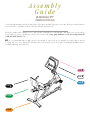
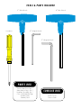
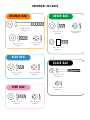
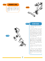
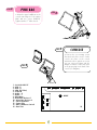
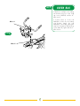
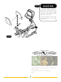
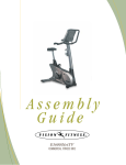
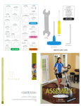
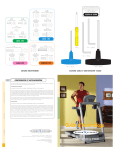
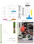
Assembly Guide R2600iNetTV COMMERCIAL FITNESS BIKE Assembly Guide R2600iNetTV COMMERCIAL FITNESS BIKE To avoid possible damage to this Fitness Bike, please follow these assembly steps in the correct order. Before proceeding, find your new Fitness Bike’s serial number located on the front axle tube, and enter here: Refer to this number when calling for service, and enter this serial number on your Warranty Card and in your own records. Be sure to read your Owner’s Guide before using your new Fitness Bike. If any parts, hardware or tools are missing, please call 1.800.335.4348, Extension 12 NOTE: It is recommended that you apply grease to the threads of each screw as you assemble your Fitness Bike to prevent loosening and noise. Also, during each assembly step, ensure that ALL screws are in place and partially threaded in before completely tightening any ONE screw. STEP 6 STEP 5 STEP 1 STEP 3 STEP 4 STEP 2 TOOLS & PARTS INCLUDED 5 MM Screwdriver Allen Wrench 6 MM 4 MM Allen Wrench L-Shaped Wrench 5 MM L-Shaped Wrench PARTS BOX Console Mast Cover, Qty: 1 Water Bottle & Cage, Qty: 1 Heart Rate Chest Strap, Qty: 1 Color-coded Hardware Bags Assembly Guide Warranty Card CONSOLE BOX iNetTV Console Owner’s Guide HARDWARE INCLUDED ORANGE BAG GREEN BAG M8x65L Screw Quantity: 2 M8 x 20L Screw Quantity: 2 M8 x 15L Screw Quantity: 4 M8 Lock Washer Quantity: 4 M8 x 20L Screw Quantity: 4 BLUE BAG BLACK BAG M8 x 15L Screw Quantity: 7 M8 Lock Washer Quantity: 6 PINK BAG M8 x 20L Screw Quantity: 2 M6 x 55L Screw Quantity: 8 M6 Lock Washer Quantity: 8 M8 Lock Washer Quantity: 4 M8 Lock Washer Quantity: 8 STEP ORANGE BAG 1 • Install the rear foot with the four lock washers (M8), two inside screws (M8x65L), and two outside screws (M8x20L). Tighten with the 5 Allen wrench. STEP 1 MM STEP 2 BLUE BAG • Slide the rubber boot onto the console mast. STEP • Locate the bundle of wires that comes from the console mast frame bracket. Wrap the wire tie coming from the bottom of the console mast around the bundle of wires. Pull the wire tie with the bundle of wires up through the top of the console mast while simultaneously sliding the mast into the frame bracket. 2 • Secure the console mast to the frame bracket with six lock washers (M8) and six screws (M8x15L). Tighten with the 5 Allen wrench. Place the seventh screw (M8x15L) in the rear of the frame bracket and tighten until snug. MM • Slide the console mast boot down and snap it into place on the side cover. • Remove the screws located half way up the console mast with the Phillips screwdriver. Attach the water bottle bracket to the console mast with these two screws. Insert the water bottle. 5 STEP 3 PINK BAG STEP • Mount the upper handlebars to the console mast using two lock washers (M8) and two screws (M8x20L). Tighten with the 5 Allen wrench. 3 MM STEP STEP • Remove the six mounting screws from the back of the console. Set the console into place on the console mast and secure it with the six screws you just removed. Tighten with the Phillips screwdriver. Connect the wires to the proper plugs in the back of the console (see diagram). 4 1 - Co-Axial Cable TV 2 - USB - B 3 - USB - A 4 - VGA (PC Video) 5 - Video IN 6 - Audio - R 7 - Audio - L 8 - Microphone 9 - Heart Rate Reciever 1 10 - Heart Rate Reciever 2 11 - 20 Pin Connector 12 - Power Plug 13 - Miles/Kilometers Switch 14 - Data Port CONSOLE 4 1 9 2 3 4 5 6 7 8 WIRES 10 12 11 13 14 6 STEP 5 GREEN BAG • Attach the seat frame to the sliding seat bracket using four socket head cap screws (M8x20L) and the 6 Allen wrench. MM • Connect Wires A on the seat handlebar to Wires B on the sliding seat bracket. Attach the seat handlebars to the sliding seat bracket using four lock washers (M8) and four screws (M8x15L). Tighten with the 5 Allen wrench. Wires A MM STEP 5 Wires B 7 STEP 6 BLACK BAG • Secure the Lumbar controlled seat back and the seat bottom to the seat frame with eight lock washers (M6) and eight screws (M6x55L). Tighten with the 4 Allen wrench. MM • Snap the plastic seat cover into place on the back of the Lumbar controlled seat. STEP 6 500 South CP Avenue • P.O. Box 280 • Lake Mills. WI 53551 toll free 1.800.335.4348 • phone 1.920.648.4090 • fax 1.920.648.3373 www.visionfitness.com 2002 Vision Fitness. All Rights Reserved. 8.02 Part #Z26RB60-AG1825PRD AG18.25PRD REV1 8