1
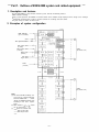
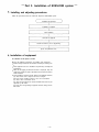
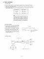
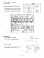
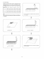
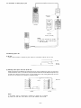
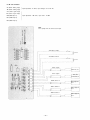
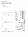
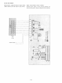
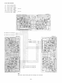
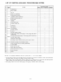
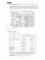
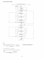
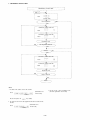
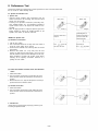
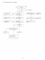
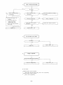
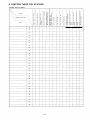
EXES-2000
EX-200
For
EXES-2000 INTERCOM SYSTEM
Fully Electronic Exchange
EX-200
INSTALLATION HAND BOOK
TOA Corporation
KOBE, JAPAN
BEFORE READING THIS HAND BOOK
This hand book forms part of installation manual for TOA EXES-2000 intercom system. Various functions and external
equipment other than normal speech may be employed in the TOA EXES-2000 intercom system according to changing
users' needs. To make such additional functions available, however, functions and equipment that satisfy customers'
needs have to be properly selected after installing, wiring and connecting the equipment. In installing the system, read
this hand book as well as Functions and Operating Instructions for EXES-2000 stations. For installation and adjustment of
each station, refer to the operating manual attached to each station.
Contents
1
BEFORE READING THIS HAND BOOK
Part 1. Outlines of EXES-2000 system and related equipment
1. Description and features
2. System configuration and each unit functions
2
2
Part 2. Installation of EXES-2000 system
3. Installing and adjusting procedures
4. Installation of equipment
4-1 Selection of the place to install
4-2 Installation of the exchange
4-3 Installation of FC-210
4-4 Installation of power supply unit
4-5 Installation of station
5. Cable installation
5-1 Cable selection
5-2 Points to remember
5-3 Wiring examples
6. Connection of equipment
6-1 Addition of LM unit
6-2 LM unit wiring
6-3 Connection of station plug to jack
6-4 Mounting option unit
6-5 Bl unit connection
6-6 RC unit connection
6-7 PC unit connection
6-8 Tl unit connection
6-9 SM unit number setting
6-10 Connection for speaker station
6-11 Connection of power source
7. Initial set-up and programming (No. 24 programming)
7-1 Procedures of initial set-up and No. 24 programming
7-2 Registration of each function
8. Performance test
8-1 Speech and function tests
8-2 Trouble-shooting at the time of installation
4
4
4
5
6
7
8
9
9
9
9
10
10
11
12
12
13
14
15
16
17
18
19
20
20
22
38
38
39
Part 3. Checking sheet for the exchange
9. Function table for stations
10. Station data table
41
42
–1–
Part 1. Outlines of EXES-2000 system and related equipment
1. Description and features
The Toa EXES-2000 is a fully electronic intercom system, and has the following features:
Wall mounted exchange.
Easy system expansion and addition of functions thanks to the modular concept employed in the design of the exchange.
Economical non-polar 2-wire system to connect between the exchange and each station.
A great variety of stations to choose from.
2. Examples of system configuration
BGM distribution
(up to 3 channels)
Alarm
Time signal annunciation
Door remote control
(2 circuits)
Station
(16 stations max.)
Power remote control
(3 circuits)
Paging output
(3 zones)
PTT control
Pager control
Tie-line
(2 circuits)
Station
(16 stations max.)
Notes
(1) The basic EX-200 exchange consists of one (1) central control unit
and 2 line modem units.
shows
"option" or additional LM units used
according to the user's requirements.
(2) When shown as
A or B
can be selected.
(3)
shows Toa standard cable,
shows one-pair cable.
shows two-pair cable.
–2–
Central control unit CC-20:
This unit is comprised of a CPU that processes the exchange procedures, a speech link consisting of a
voice switch circuit and a signal tone generating circuit, and a power circuit.
Line modem unit LM-20:
This unit is comprised of a circuit for sending out signals from the station to the speech path, a circuit to
transmit signals from the speech link to the station, a receiver and a scanning circuit for dial data, and a
terminal block. Wires from the station are connected directly to the terminal block on the LM unit. A
maximum of 4 stations can be connected per LM unit, and up to 4 LM units can be mounted in the EX-200
and FC-210.
BGM unit BI-20:
This unit is comprised of a circuit to send out signals from BGM equipment, and alarm or time signals to
the LM unit, a circuit that transmits control signals from the alarm or timer to the CPU, and a terminal
block. The Bl unit is mounted in the exchange from the bay solely intended for this unit.
Remote control unit RC-20:
This unit is formed from relays for door remote control, power remote control and PTT control, a circuit to
activate these relays, and a terminal block. It is possible to use any bay for "option" unit to mount the
RC-20 in the exchange.
Pager control unit PC20:
This unit has the control output to remotely operate the TR-321 or TR-322 pager controller as well as the
serial data output that complies with ESPA standards. The PC-20 may be mounted in the exchange from
any bay for "option" unit.
Speech message unit SM-20:
This unit includes a circuit to convert audio signals into digital signals, a memory storing the converted
signals, and a circuit that converts digital signals into audio signals. A single SM unit has a memory
covering 4 stations, and a control circuit. A maximum of 5 SM units can be mounted in the EX-200
exchange (in this event, no room is left for mounting the RC unit, PC unit and Tl unit in the exchange), and
up to 6 in the FC-210 cabinet. However, an entire system can only accept up to 8 of the SM-20 unit.
Tie-line unit TI-20:
This unit is comprised of DTMF transmitting and receiving circuits for exchanging dial data with the other
exchange, and a circuit for transmitting voice signals.
Power transformer unit PU-200:
This unit supplies power to the EX-200 and the FC-210. Power output is 20V AC, 2.5 amperes for both
exchanges.
Extension cabinet FC-210:
This unit is employed when a system has more than 16 stations or a number of "option" units are used. A
maximum of 4 LM-20's and 6 "option" units can be mounted in the FC-210. Note that the YR-820 and
YR-821 cables are necessary for adding the LM-20 and the "option" unit, respectively.
–3–
Part 2. Installation of EXES-2000 system
Installing and adjusting procedures
Follow the procedures below to install and adjust the EXES-2000 system:
Installation and adjustment
Installation of equipment
Cable installation
Connection of equipment
Selection of function by No. 24 programming
Speech and performance tests
Installation of equipment
4-1 Selection of the place to install
Observe the following precautions in installing each equipment:
Allow for weight exerted on the wall when mounting the exchange on
it.
Each equipment is to be so installed as to permit easy checkup and
maintenance.
When the PA paging or talk-back function is employed, keep the
station and speaker as apart as possible from each other in order to
avoid feedback.
Do not install the exchange nor the station in the following locations:
(A) Areas where unit is exposed to heat or sunlight.
(B) Areas where metallic particles or dust are accumulated.
(C) Areas close to chemicals or oil.
(D) Areas of high moisture or near the window where unit may be
splashed by rain water.
(E) Areas close to high voltage equipment or where strong electric
field exists.
–4–
4-2 Installation of the exchange
Follow the procedures below to install the EX-200 exchange:
Unscrew 4 side screws to
remove the top case.
Fix the exchange on the wall
using fixing holes provided on
the bottom case.
Knock-out hole (for wiring)
Dimensions
–5–
4-3 Installing FC-210 extension cabinet
Follow the procedures below to install the FC-210 cabinet:
Unscrew screws that hold the top case to a chassis at 4 places
in the sides of a cabinet.
Insert attached brackets (2 pieces) into bracket
receptacles on the bottom case of the EX-200.
Fit bracket receptacles of the FC-210 into the
brackets.
Fix the cabinet on the wall through fixing holes
provided on its bottom case.
Connect the connector CN-5 on the CC-20 card
mounted in the EX-200 to the connector CN-4 on the
printed circuit board of the FC-210 using the
attached GND connector.
(EX-200)
Remove a rubber membrane of 2 bushings on the
bottom case of the EX-200 and FC-210 to allow the
cable entry.
Bracket
Bracket
Knock-out hole (for wiring)
(FC-210)
Note
(1) Since the YR-820 and YR-821 cables are to be used
for connecting the FC-210 to the EX-200 exchange,
there is a limit to spacing between the two units. You
should allow for this limit and fix them according to
dimensions shown at right when they are mounted
on the wall.
(2) Allow for sufficient spacing for screwing and unscrewing the top cover when mounting on the wall.
Knock-out hole (for wiring)
–6–
Dimensions
4-4 Installation of PU-200 power supply unit
Follow the procedures below to install the PU-200:
Remove 4 case fixing screws and fit the attached
wall mounting kit.
Case fixing screw
Wall mounting kit
Fix on the wall. In the event that unit is mounted
on the wall with wood screws, use the attached screws.
Dimensions
–7–
4-5 Installation of Stations
To install stations, make connections by using station jack model YC-601 (Wall-mounted type) or YC-603
(Flush-mounted type). Since the length of station cord is 3 meters (9.8 feet), the station jack needs to be mounted
within this length.
Station jack YC-603 (Flush-mounted type)
Station jack YC-601 (Wall-mounted type)
Mount this jack on a wall, pillar or desk. Utilize either knock-out
Mount switch box and make piping and wiring arrangements
before the station jack is installed.
holes provided on the top and the bottom of the case or a cable
entry hole in the base for connecting the cables to the exchange.
Wall
Knock-out hole
(provided on the top and bottom)
Base
Screw
for base
Plate
Case
Base
Cable entry hole
Screw
Screw
for box
Cable entry hole
Screw
for case
Case
Switch box
Screw
for plate
Other stations
Please refer to instruction manual of each station.
–8–
5. Cable installation
5-1 Cable selection
Use 2-conductor telephone or interphone cables for connection from the exchange to the station.
Be sure to use a multi-pair twisted cable such as an indoor cable and CCP-(A)P cable when the connection is
made via the external terminal board.
Select appropriate cables according to the following table that shows the relationship between cable diameter
and transmission distance.
Core diameter
Service distance
0.5 mm
1.0km (1.5km)
0.65mm
1.5km (2.5km)
0.9 mm
2.5km (3.5km)
Note
The figure in a parenthesis is the maximum cable length
and shown at its left is the normal service distance. The
system supplied from the factory is pre-wired for the
normal service distance. To obtain the maximum cable
length, replace the corresponding resistor R31, R39,
R51 or R59 (390k ohms) on the LM unit corresponding to
the line with that of 680k ohms. (See paragraph 6-10.)
5-2 Points to remember
The multi-pair cable used for wiring of the EXES-2000
system must not be jointly used as a power cable or
Not allowed
data transmitting cable for facsimile, etc.
Do not connect an unused cable to the exchange.
Do not connect an unused cable to a connection
cable between the exchange and the station.
When utilizing multi-core cables already in use for
wiring, confirm they are twisted paired cables. Unless
Exchange
Station
Not allowed
they are twisted cables, they may not be used due to
interference between lines.
5-3 Wiring examples
Multi-pair cable
Exchange
Stations
Indoor
terminal
board
2-conductor interphone cables
–9–
Stations
6. Connection of equipment
6-1 Addition of LM unit
1
20~23
Position of
SW1/SW2
1
2
24~27
2
Mounted
3
28~31
3
in EX-200
4
32-35
4
LM unit No.
A basic system using the EX-200 exchange is comprised of 8
stations (2 LM units). The LM unit needs to be added according to
the following procedures when more stations are required.
(1) Establishment of the LM unit number
Set switches SW-1 and SW-2 on the LM unit to positions as
shown in the table at right according to the station numbers
connected to each LM unit. Since the LM units of a basic system
are pre-set as No. 1 and No. 2 when supplied from the factory,
the LM number has to be fixed only for the additional units.
Station No.
5
36~39
1
6
40~43
2
7
44~47
3
8
48~51
4
Remarks
Mounted
in FC-210
(2) Mounting LM unit
(For the system with up to 16 stations)
Insert the additional LM units into the exchange and connect
CN1 of the LM unit to the LM unit connection cable.
Additional LM units
LM unit connection cable
CC unit
YR-820
(More than 16 stations)
After connecting between the EX-200 and the FC-210 with the
YR-820, mount the LM units. An earth wire of the YR-820 is to be
connected to the earth terminal of the FC-210.
Earth wire
EX-200
– 10 –
FC-210
6-2 LM unit wiring
Follow the procedures below to connect a station cable to the
terminal block CN 2 on the LM unit. The following list shows
relationships between the CN 2 number and the station number.
LM No.
1
2
3
4
5
6
7
8
1
20
24
28
32
36
40
44
48
2
21
25
29
33
37
41
45
49
3
22
26
30
34
38
42
46
50
4
23
27
31
35
39
43
47
51
CN2 No.
Strip a covering from a cable and insert the conductor into
the connector.
Note
Protectors attached to the LM units mounted in the exchange are
shock absorbers used only during transit. Remove them at the time
of installation.
Pull the screwdriver.
Remove CN2.
Mount the terminal block on the LM unit after completing
cable connection.
Insert a screwdriver.
– 11 –
6-3 Connection of station plug to jack
2-pin plug
YC-602
HF-210M
Cover
2-pin jack
YC-601 (or YC-603)
Notes
(1) Use 4"×2" back box for YC-603.
(2) Terminals 1 and 2 inside the jack
have no polarity.
CN2
6-4 Mounting option unit
(1) Bl unit
Insert the Bl unit into its exclusive bay and connect its connector to CN4 on the CC unit.
(LM unit)
(Bl unit)
(CC unit)
(2) Mounting other option units than the Bl unit
Option units other than the BI-20 are all connected to the CC unit via a common bus and so, any bay can be
used to mount them so far as it is not the one solely intended for the Bl unit. The EX-200 exchange has 5 bays
for option units, while the FC-210 has 6 bays. Insert the option units in order, stating with the bay closest to
the CC unit, and connect the connector as illustrated below.
Earth wire
YR-821
FC-210
EX-200
Notes
(1) No YR-821 cable is needed when a maximum of 5 option units is mounted.
(2) Connect an earth wire of the YR-821 to the earth terminal of the FC-210.
– 12 –
6-5 Bl unit connection
AL (Alarm starting input)
TM (Timer starting input)
Input impedance: 1k ohms, Input voltage: 5V to 24V DC
ALS (Alarm signal input)
IMS (Timer signal input)
BS0 (BGM input 1)
Input impedance: 10k ohms, Input level: -10 dBv
BS1 (BGM input 2)
BS2 (BGM input 3)
Note
Cut a jumper wire to connect each input.
<Activation of alarm>
5V~24
<Activation of timer>
5V~24
<Alarm signal>
Alarm tone, etc.
<Timer signal>
chime, time
annunciation, etc.
<BGM channel 1>
<BGM channel 2>
<BGM channel 3>
– 13 –
BGM equipment
No. 1
BGM equipment
No. 2
BGM equipment
No. 3
6-6 RC unit connection
PR1 (Power remote control 1/general purpose control 1)
PR2 (Power remote control 2/general purpose control 2)
PR3 (Power remote control 3/general purpose control 3)
Maximum contact capacity: 125VA (125V AC or 30V DC 1A)
DR1 (Door remote control 1)
DR2 (Door remote control 2)
PTT.C (PTT control)
P1 (Audio signal output for paging zone 1)
P2 (Audio signal output for paging zone 2)
Output: –10 dBv (unbalanced)
P3 (Audio signal output for paging zone 3)
Door
locking
Radio
equipment
Station
AC
– 14 –
6-7 PC unit connection
PG0, PG1-PG11 (parallel data output for pager control)
Outputs solely intended for TR-321 controllers.
SERIAL OUTPUT (serial data output for pager control)
Maximum contact capacity: 125 VA (125V AC or 30V DC 1A)
Data transmitting speed: 10 pps (To comply with ESPA standards)
Serial data output
– 15 –
6-8 Tl unit connection
1-2:
Lines for station No.25
3-4:
Lines for station No.26
5-6:
Tie-line output –10dBm
7-8:
Tie-line input –10dBm
No. 25
9-10: Tie-line output –10dBm
11-12 Tie-line input –10dBm
No. 26
Exchange A
To station No. 25 of exchange A
To station No. 26 of exchange A
Exchange C
Exchange B
To station
No. 25 of exchange C
To station
No. 26 of exchange C
To station No. 26 of exchange B
To station No. 25 of exchange B
Note
Dotted lines stand for wiring when two exchanges are connected.
– 16 –
6-9 SM unit number setting
A maximum of 8 SM units may be used in a system. Establish each unit number by operating SW1
switch.
1 s t card
2nd card
3rd card
4th card
5th card
6th card
7th card
8th card
– 17 –
6-10 Connection for speaker station
When the speaker station function is employed, cut the corresponding resistor leads as well as jumper
wires according to the following table.
Station No.
LM No.
1
20
21
22
23
2
24
25
26
27
3
28
29
30
31
4
32
33
34
35
5
36
37
38
39
6
40
41
42
43
7
44
45
46
47
8
48
49
50
51
Resistor to cut
R74
R87
R100
R113
Resistor to set
service distance
R31
R39
R51
R59
– 18 –
6-11 Connection of power source
Connect CN1 on the CC unit and CN3 on the FC-210 printed circuit board to AC output of the PU-200
or to the external power supply. Also, connect CN5 on the CC unit to CN4 on the FC-210 printed circuit
board with the attached connection cable.
Note
Select the desired voltage by means of
the voltage selector. The voltage selector is pre-set to 120V or 240V when
supplied from the factory.
(FC-210)
Voltage selector
(PU-200)
– 19 –
7. Initial set-up and programming (No. 24 programming)
Functions the EXES-2000 system has besides basic functions include selectable functions capable of
being freely selected by station No. 24 programming, and additional functions that can be obtained by
connecting optional equipment. To make the selectable function or additional function available,
establish No. 24 programming after making initial set-up. Once these procedures have been
completed, the initial set-up is no longer required when adding the equipment or changing the function.
All the functions available from the EXES-2000 are shown in the table on page 21.
7-1 Procedures of initial set-up and No. 24 programming
(1)
Turn on SW2 switch of the memory backup battery on the CC unit.
(2)
Verify that the exchange is correctly wired and each module unit is correctly mounted in the
exchange. Then plug the power cord of the PU-200 in a wall AC outlet.
(3)
Confirm that the power indicator lamp of the CC unit in the EX-200 and the one on the FC-210 both
come on.
(4)
Connect the station to No. 24 connector of the LM unit in the exchange and confirm that a brief
tone is audible continuously. The brief tone is a warning tone to indicate that the initial set-up has
not yet been made.
(5)
Place SW1 program switch on the CC unit in the ON position.
(6)
Confirm a dial tone is heard when depressing
(7)
Confirm that a confirmation tone is heard by dialing
of No. 24 station.
10 times
(This procedure is not needed in the event of the addition or change of the function.)
(8)
Register functions according to instructions on dial operation in section 7-2. Record all the
functions of each station in the station function table on page 40, which is to be retained for the
system maintenance purposes.
(9)
Set SW1 program switch on the CC unit to OFF.
– 20 –
LIST OF FUNCTION AVAILABLE FROM EXES-2000 SYSTEM
No. Classification
1.
Camp-on-busy
2.
Busy call-back
3.
Mic off
4,
Muster sub relationship
Privacy/Camp-on-privacy
5.
6.
Call
Continuous call tone station (1*)
7.
Handset operated station (2*)
8.
Press-to-talk
9.
PTT
Talkback
Press-to-talk control
10.
11.
Personal number call
12.
Conference
Call transfer
13.
14.
Selectable functions Additional
Basic (No.
24 programming
function must be established) functions
Function
Transfer
Call forwarding
15.
Secretary transfer
16.
Hurry up
17.
Executive (Highest) priority
18.
Station paging call-up (all-call paging + 3 zone paging calls) and its
response (3*)
19.
20.
Paging
PA paging call-up (all-call paging + 3 zone paging) and its response (3*)
Selected station paging
21.
Emergency all-call paging
22.
PA paging & power remote/3-channel general purpose control
23. Selection
Time-Out of paging call (no limit/20 seconds)
24.
Speech message hurry up recording (with/without)
25.
3-channel BGM
26.
Alarm and time signal
27.
Pager calling and response
28.
Door remote control (2 circuits)
29.
Speech message
30.
Tie-line
Note that × × / Y Y (Example. with/without of Item No. 24) shows either
××
or YY can be adopted.
1* The station having its Privacy switch in the OFF mode can select either a "brief" call tone or "continuous" call tone. (The station without
the Privacy switch is the same as one having its Privacy switch in OFF.)
2* With the Privacy switch in the ON position, either the "Privacy tone" or "continuous tone" can be selected. (The handset operated
station is always in the same Privacy state as the station whose Privacy switch is set to OFF.
3* Each paging channel can be either station paging or PA paging or combined station and PA paging.
– 21 –
Precautions
The CC unit incorporates a CMOS IC. Particular care is to be taken about its damage static electricity causes
when you make switch settings.
Lithium battery is used for a memory backup battery BAT-1, which maintains the important data stored in a
memory during power outage. A life span of the lithium battery largely varies depending on ambient
temperature and a space of time that the exchange was used. To be on a safe side, therefore, we suggest that
the battery be replaced every 3 years. Be sure to set up No. 24 programming again after its replacement.
7-2 Registration of each function
1 Dial operations to select functions
Dial operations
Functions
Not available
Available
General purpose
control (*1)
Time out of paging (20 seconds)
No. 25 tie-line
(*2)
No. 26 tie-line
(*2)
BGM/alarm/time
annunciation (BI-20)
Speech message
hurry-up tone
Call forwarding
(*1) General purpose control and PA paging are alternative functions. So dialing as to select general
purpose control will automatically deprive the system of the PA paging function.
(*2) Depress dial keys as shown in a parenthesis when the "tie-lined" exchange is the
EX-610/620/630.
(*3) Making initial settings puts the system in the "not available" mode.
– 22 –
2. HIGHEST EXECUTIVE PRIORITY
HIGHEST EXECUTIVE PRIORITY
STEP 1
Touch
Function Code
NO
New Registration?
YES
Executive Station No.
Touch
Executive Station No.
Touch
Confirmation tone
NO
New Registration finished?
YES
NO
Release?
YES
Executive Station No.
Touch
Executive Station No.
Touch
Confirmation tone
NO
Release finished?
YES
Return
NOTES
1. To allow all the stations to have this function,
(Confirmation tone
will be heard.)
Touch
3. Re-start at Step 1 when mis-dialing occurs.
(All other registrations remain valid.)
10 times
key steadily.
Be sure to depress the
2. To release at one time the data programmed into all the stations for this
function,
(Confirmation tone
will be heard.)
Touch
10 times
– 23 –
3. CONTINUOUS CALLING TONE
CONTINUOUS CALLING TONE
STEP 1
Touch
Function Code
NO
New Registration?
YES
Continuously Called Station No.
Touch
Continuously Called Station No.
Touch
Confirmation tone
NO
New Registration finished?
YES
NO
Release?
YES
Continuously Called Station No.
Touch
Continuously Called Station No.
Touch
Confirmation tone
NO
Release finished?
YES
Return
NOTES
1. To allow all the stations to have this function,
(Confirmation tone
will be heard.)
Touch
10 times
Be sure to depress the
key steadily.
2. To release at one time the data programmed into all the stations for this
function,
(Confirmation tone
will be heard.)
Touch
10 times
– 24 –
3. Re-start at Step 1 when mis-dialing occurs.
(All other registrations remain valid.)
4. STATIONS ALLOWED ACCESS TO PAGING
(All stations are registered for this function when initial set-up is made)
STATIONS ALLOWED ACCESS TO PAGING
STEP 1
Touch
Function Code
NO
New Registration?
YES
Allowed Station No.
Touch
Allowed Station No.
Touch
Confirmation tone
NO
New Registration finished?
YES
NO
Release?
YES
Allowed Station No.
Touch
Allowed Station No.
Touch
Confirmation tone
NO
Release finished?
YES
Return
NOTES
1. To allow all the stations to have this function,
(Confirmation tone
will be heard.)
Touch
3. Re-start at Step 1 when mis-dialing occurs.
(All other registrations remain valid.)
10 times
Be sure to depress the
key steadily.
2. To release at one time the data programmed into all the stations for this
function,
(Confirmation tone
will be heard.)
Touch
10 times
– 25 –
5. STATIONS ALLOWED ACCESS TO EMERGENCY CALL
STATIONS ALLOWED ACCESS TO EMERGENCY CALL
STEP 1
Touch
Function Code
NO
New Registration?
YES
Allowed Station No.
Touch
Allowed Station No.
Touch
Confirmation tone
NO
New Registration finished?
YES
NO
Release?
YES
Allowed Station No
Touch
Allowed Station No.
Touch
Confirmation tone
NO
Release finished?
YES
Return
1. To allow all the stations to have this function,
3. Re-start at Step 1 when mis-dialing occurs.
(All other registrations remain valid.)
(Confirmation tone
will be heard.)
Touch
10 times
Be sure to depress the
key steadily.
2. To release at one time the data programmed into all the stations for this
function,
(Confirmation tone
will be heard.)
Touch
10 times
– 26 –
6. HANDSET STATION REGISTRATION
HANDSET STATION REGISTRATION
STEP 1
Touch
Function Code
NO
New Registration?
YES
Handset Station No.
Touch
Handset Station No.
Touch
Confirmation tone
NO
New Registration finished?
YES
NO
Release?
YES
Handset Station No.
Touch
Handset Station No.
Touch
Confirmation tone
NO
Release finished?
YES
Return
NOTES
1. To allow all the stations to have this function,
(Confirmation tone
will be heard.)
Touch
3. Re-start at Step 1 when mis-dialing occurs.
(All other registrations remain valid.)
10 times
Be sure to depress the
key steadily.
2. To release at one time the data programmed into all the stations for this
function,
(Confirmation tone
will be heard.)
Touch
10 times
– 27 –
7. STATIONS ALLOWED ACCESS TO DOOR REMOTE CONTROL AND GENERAL PURPOSE CONTROL
STATIONS ALLOWED ACCESS TO DOOR REMOTE CONTROL AND GENERAL PURPOSE CONTROL
STEP 1
Touch
Function Code
NO
New Registration?
YES
Allowed Station No.
Touch
Allowed Station No.
Touch
Confirmation tone
NO
New Registration finished?
YES
NO
Release?
YES
Allowed Station No.
Touch
Allowed Station No.
Touch
Confirmation tone
NO
Release finished?
YES
Return
NOTES
1. To allow all the stations to have this function,
3. Re-start at Step 1 when mis-dialing occurs.
(All other registrations remain valid.)
(Confirmation tone
will be heard.)
Touch
10 times
Be sure to depress the
key steadily.
2. To release at one time the data programmed into all the stations for this
function,
(Confirmation tone
will be heard.)
Touch
10 times
– 28 –
8. STATIONS ALLOWED ACCESS TO SPEECH MESSAGE
STATIONS ALLOWED ACCESS TO SPEECH MESSAGE
STEP 1
Touch
Function Code
NO
New Registration?
YES
Allowed Station No.
Touch
Allowed Station No.
Touch
Confirmation tone
NO
New Registration finished?
YES
NO
Release?
YES
Allowed Station No.
Touch
Allowed Station No.
Touch
Confirmation tone
NO
Release finished?
YES
Return
NOTES
1. To allow all the stations to have this function,
(Confirmation tone
will be heard.)
Touch
3. Re-start at Step 1 when mis-dialing occurs.
(All other registrations remain valid.)
10 times
key steadily.
Be sure to depress the
2. To release at one time the data programmed into all the stations for this
function,
(Confirmation tone
will be heard.)
Touch
10 times
– 29 –
9. DOOR SUBSTATION REGISTRATION
DOOR SUBSTATION REGISTRATION
STEP 1
Touch
Function Code
NO
New Registration?
YES
Allowed Station No.
Touch
Allowed Station No.
Touch
Confirmation tone
NO
New Registration finished?
YES
NO
Release?
YES
Allowed Station No.
Touch
Allowed Station No.
Touch
Confirmation tone
NO
Release finished?
YES
Return
NOTES
1. To allow all the stations to have this function,
3. Re-start at Step 1 when mis-dialing occurs.
(All other registrations remain valid.)
(Confirmation tone
will be heard.)
Touch
10 times
Be sure to depress the
key steadily.
2. To release at one time the data programmed into all the stations for this
function,
(Confirmation tone
will be heard.)
Touch
10 times
– 30 –
10. SECRETARY TRANSFER
SECRETARY TRANSFER
STEP 1
Touch
Function Code
NO
New Registration?
YES
Executive Station No.
Secretary Station No.
Executive Station No.
Secretary Station No.
Touch
Touch
Confirmation tone
NO
New Registration finished?
YES
NO
Release?
YES
Executive Station No.
Executive Station No.
Executive Station No.
Executive Station No.
Touch
Touch
Confirmation tone
NO
Release finished?
YES
Return
NOTES
1. To release at one time the data programmed into all the stations for this
function,
3. Programming of Secretary Transfer can be made in a daisy chain method.
For their examples, refer to the following sketch.
(Confirmation tone
will be heard.)
Touch
10 times
2. Re-start at Step 1 when mis-dialing occurs.
(All other registrations remain valid.)
– 31 –
11. MASTER/SUB RELATIONSHIP
MASTER/SUB RELATIONSHIP
STEP 1
Touch
Function Code
NO
New Registration?
YES
Sub Station No.
Master Station No.
Sub Station No.
Master Station No.
Touch
Touch
Confirmation tone
NO
New Registration finished?
YES
NO
Release?
YES
Sub Station No.
Sub Station No.
Sub Station No.
Sub Station No.
Touch
Touch
Confirmation tone
NO
Release finished?
YES
Return
NOTES
2. Re-start at Step 1 when mis-dialing occurs.
(All other registrations remain valid.)
1. To release at one time the data programmed into all the stations for this
function,
(Confirmation tone
will be heard.)
Touch
10 times
– 32 –
12. REGISTRATION OF STATIONS TO REFUSE ALL-CALL PAGING
REGISTRATION OF STATIONS
TO REFUSE ALL-CALL PAGING
Step 1
Dial
Function code
Yes.
No.
New registration?
Registration
(allowed station No.)
Dial
Step 2
plus
Step 2
Confirmation
tone
(allowed station No.)
Dial
Confirmation
tone
plus
Repeat twice.
Repeat twice.
No.
Registration finished?
Registration of next allowed station.
Yes.
Other registration mode
or registration finished.
NOTES
1. All the stations are registered for this function when initial set-up is made.
2. To cancel at one time the data programmed into all the stations for this
function,
4. To register stations having consecutive station numbers for this function,
First station No. Last station No.
Dial
Repeat twice.
(Confirmation tone
will be heard.)
Dial
10 times
5. Re-start at Step 1 when mis-dialing occurs. (All other registrations remain
valid.)
3. To register all the stations for this function,
(Confirmation tone
will be heard.)
Dial
10 times
Depress the
key steadily.
– 33 –
13. REGISTRATION OF STATION TO REFUSE ZONE 1 PAGING
REGISTRATION OF STATION TO
REFUSE ZONE 1 PAGING
Step 1
Dial
Function code
Yes.
No.
New registration?
Registration
(allowed station No.)
Dial
Step 2
plus
Step 2
Confirmation
tone
(allowed station No.)
Dial
Confirmation
tone
plus
Repeat twice.
Repeat twice.
No.
Registration finished?
Registration of next allowed station.
Yes.
Other registration mode
or registration finished.
NOTES
1. All the stations are registered for this function when initial set-up is made.
4. To register stations having consecutive station numbers for this function,
First station No. Last station No.
2. To cancel at one time the data programmed to all the stations for this
function,
Dial
Repeat twice.
(Confirmation tone
will be heard.)
Dial
10 times
5. Re-start at Step 1 when mis-dialing occurs. (All other registrations remain
valid.)
3. To register all the stations for this function,
(Confirmation tone
will be heard.)
Dial
10 times
Depress the
key steadily.
– 34 –
14. REGISTRATION OF STATIONS TO REFUSE ZONE 2 PAGING
REGISTRATION OF STATIONS TO
REFUSE ZONE 2 PAGING
Step 1
Dial
Function code
Yes.
No.
New registration?
Registration
(allowed station No.)
Dial
Step 2
plus
Step 2
Confirmation
tone
(allowed station No.)
Dial
Confirmation
tone
plus
Repeat twice.
Repeat twice.
No.
Registration finished?
Registration of next allowed station.
Yes.
Other registration mode
or registration finished.
NOTES
1. All the stations are registered for this function when initial set-up is made.
2. To cancel at one time the data programmed to all the stations for this
function,
4. To register stations having consecutive station numbers for this function,
First station No. Last station No.
Dial
Repeat twice.
(Confirmation tone
will be heard.)
Dial
10 times
5. Re-start at Step 1 when mis-dialing occurs. (All other registrations remain
valid.)
3. To register all the stations for this function,
(Confirmation tone
will be heard.)
Dial
10 times
Depress the
key steadily.
– 35 –
15. REGISTRATION OF STATIONS TO REFUSE ZONE 3 PAGING
REGISTRATION OF STATIONS TO
REFUSE ZONE 3 PAGING
Step 1
Dial
Function code
Yes.
No.
New registration?
Registration
(allowed station No.)
Dial
Step 2
plus
Step 2
Confirmation
tone
(allowed station No.)
Dial
Confirmation
tone
plus
Repeat twice.
Repeat twice.
No.
Registration finished?
Registration of next allowed station.
Yes.
Other registration mode
or registration finished.
NOTES
1. All the stations are registered for this function when initial set-up is made.
4. To register stations having consecutive station numbers for this function,
First station No. Last station No.
2. To cancel at one time the data programmed to all the stations for this
function,
Dial
Repeat twice.
(Confirmation tone
will be heard.)
Dial
10 times
5. Re-start at Step 1 when mis-dialing occurs. (All other registrations remain
valid.)
3. To register all the stations for this function,
(Confirmation tone
will be heard.)
Dial
10 times
Depress the
key steadily.
– 36 –
16. REGISTRATION OF STATIONS TO REFUSE ALARM AND TIME ANNUNCIATION
REGISTRATION OF STATIONS TO REFUSE
ALARM AND TIME ANNUNCIATION
Step 1
Dial
Function code
Yes.
No.
New registration?
Registration
(allowed station No.)
Dial
Step 2
plus
Step 2
Confirmation
tone
(allowed station No.)
Dial
Confirmation
tone
plus
Repeat twice.
Repeat twice.
No.
Registration finished?
Registration of next allowed station.
Yes.
Other registration mode
or registration finished.
NOTES
1. All the stations are registered for this function when initial set-up is made.
2. To cancel at one time the data programmed into all the stations for this
function,
4. To register stations having consecutive station numbers for this function,
First station No. Last station No.
Dial
Repeat twice.
(Confirmation tone
will be heard.)
Dial
10 times
5. Re-start at Step 1 when mis-dialing occurs. (All other registrations remain
valid.)
3. To register all the stations for this function,
(Confirmation tone
will be heard.)
Dial
10 times
Depress the
key steadily.
– 37 –
8. Performance Test
After finishing station No.24 programming, perform operation tests from each station. Write down
the test results in "Initial Checking Sheet".
8-1 Speech and Function Tests
1. Speech Test
* Under the normal condition, make conversation using the
stations connected to the exchange and check the sound
volume and sound quality.
* According to the operation environment (surrounding noise,
echo, installed location, etc.), the microphone sensitivity or
speaker volume needs to be adjusted for hands-free conversation.
* When the paging function is employed, adjust the gain of the
paging amplifier or change the installed location of the
speakers and stations to eliminate feed-back.
Noisy area
< Method of Speech test>
Quiet area
Station A
Station B
Voice from station B is interrupted.
Surrounding noise at
station A has dominance.
(Voice from station B is
almost impossible.)
key to talk
Press
and release it to listen.
Speak loudly or
key to talk.
Press
(1) Hands-free conversation
1. Call the other station.
2. Start conversation about 50 cm away from each station to
check the sound quality and its volume.
3. Confirm that the automatic voice switching allows for smooth
conversation.
4. When the other station is in a very noisy area, the voice
switches are liable to fail to work properly, causing the voice
from the station in a quiet area to be interrupted. In this case,
adjust microphone sensitivity and speaker sound volume
according to the operating instructions contained in a
package of each station.
(2) Conversation between a handset station and a handsfree
station
1. Call the other station.
2. Start conversation and check the sound quality and sound
volume and also confirm that simultaneous conversation is
possible.
3. When feed-back occurs, adjust the microphone sensitivity or
speaker volume of the hands-free station.
(3) Handset conversation
1. Call the other station.
2. Start conversation and check the sound quality and sound
volume and also confirm that simultaneous conversation is
possible.
2. Function Test
Confirm that each function works properly by performing tests
according to operation manual.
– 38 –
Trouble-shooting at the time of installation
(1 )
Cannot dial
No
(Specified stations)
All stations?
Yes
Check AC/DC fuses
Check wirings of power
cable
No
Power indicator lamp on
exchange and
FC-210 is lit normally?
Switch settings for SW1 and
SW2 on LM are made properly?
Set switches
properly
Yes
Yes
Mount them in correct
positions
No
Each unit is mounted in a
correct position?
Is wiring to the station correct?
Yes
Make station No.24
programming
No
Station No.24
programming is completed?
Yes
No
DC voltage normal?
(+5V, +24V)
Yes
No
Voltage becomes normal when
all the units are removed?
Yes
Replace CC
Replace CC
Replace units that cause
the voltage to return to
normal when they are removed.
– 39 –
Replace station
that order
LM
CC in
Wire correctly;!
(2)
Noise is heard from the station
Yes
All stations?
No
No
Noise encountered during
conversation?
Noise encountered during
conversation?
No
Check wiring between the exchange
and station
Yes
Yes
Check power supply of the
exchange
Check wiring between the
exchange and external
equipment (BGM, timer)
Check wiring between EX-200
and FC-210
Wired in a proper pair?
No
Wire in a proper pair
Yes
Cable contains any computers
data lines?
Yes
Separate from computers data lines
No
Replace CC
Replace station
(3)
LM
No conversation can be heard
All stations?
No
Yes
Replace station
Replace CC
(4)
LM
Paging is impossible.
Did you make proper No.24 programming
No
Yes
Make No. 24 programming
Replace LM
(5) Other troubles
Additional functions cannot be operated.
Wrong wiring. Wrong DIP switch settings. Error in No. 24 programming.
Selectable functions cannot be operated.
Error in No. 24 programming.
– 40 –
CC
Function
Hardwired Station No.
Name
20
21
22
23
24
25
26
27
28
29
30
31
32
33
34
35
36
37
38
39
40
41
42
43
44
45
46
47
48
49
50
– 41 –
Stations to refuse alarm and
time annunciations.
Stations to refuse zone 3
paging
Stations to refuse zone 2
paging
Stations to refuse zone 1
paging
Stations to refuse
incoming all-call paging.
Master Station No.
Secretary Station No.
Door Substation
Speech message
Stations Allowed Access to Door
Remote Control and
General Purpose Control
Stations Allowed Access to
Emergency All-Call paging
Handset Station Registration
Stations Allowed Access
to paging
Continuous Calling Tone
Highest Executive Priority
9. FUNCTION TABLE FOR STATIONS
Function Table for Stations
10. STATION DATA TABLE
Type of stations
Item
Station No.
Name
Check if conversation can be
made normally.
Station Data Table
20
21
22
23
24
25
26
27
28
29
30
31
32
33
34
35
36
37
38
39
40
41
42
43
44
45
46
47
48
49
50
– 42 –
Printed in Japan
133-06-135-6C