1
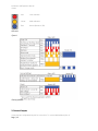
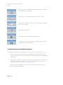
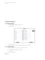
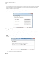
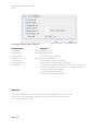
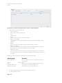
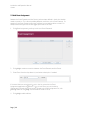
Installation and Operation Manual
Lismax
Installation and Operation Manual
Lismax
Page | 1
Installation and Operation Manual
Lismax
040112/Ver A
TL-100045
About this document
This document describes the installation and configuration of the Lismax. It also
describes the administrational part of Duty Assignment i.e. the configuration and
administration of events and actions related to a specific event, and where action chains
with success/failure conditions and access rights for the users are handled. These activities
requires a trained system administrator.
Duty Assignment is where the locations, in for example a hospital, and the conditions for
event elements are set up. It is operated on a daily basis by for example a nurse. A
description of how to assign users to specific locations and associated events is found in the
User Manual, Duty Assignment TD 92904EN.
How to use this document
The document is mainly intended for Ascom installation personnel and a local administrator
for normal system maintenance.
Page | 2
Installation and Operation Manual
Lismax
Table of Contents
1.
Introduction .......................................................................................................................................... 6
1.1
Caution and Notes ........................................................................................................................ 6
1.2
Intended Use ................................................................................................................................. 7
1.3
System Overview........................................................................................................................... 8
1.4
Licenses and Technical Specifications ........................................................................................... 9
1.5
Included in Delivery ...................................................................................................................... 9
1.6
Symbols and Descriptions ............................................................................................................. 9
1.7
Requirements .............................................................................................................................. 10
1.7.1
2.
3.
PC Requirements................................................................................................................. 10
1.8
Technical Support ....................................................................................................................... 10
1.9
Abbreviations and Glossary ........................................................................................................ 10
Installation .......................................................................................................................................... 11
2.1
Hardware Installation, Cables and Connectors........................................................................... 11
2.2
Information required for Setup .................................................................................................. 11
2.3
Getting Started............................................................................................................................ 12
2.4
Description of LED indicators ...................................................................................................... 12
2.5
Internal Outputs .......................................................................................................................... 13
2.6
Error Relay................................................................................................................................... 14
2.7
Licenses ....................................................................................................................................... 14
Configuration ...................................................................................................................................... 14
Page | 3
Installation and Operation Manual
Lismax
4.
5.
3.1
The Graphical User Interface (GUI) ............................................................................................. 14
3.2
Authentication Levels and Default Passwords ............................................................................ 15
3.3
Platform Configuration ............................................................................................................... 16
3.3.1
Network Settings................................................................................................................. 16
3.3.2
Licenses Numbers ............................................................................................................... 16
3.3.3
UNS...................................................................................................................................... 17
3.3.4
User Server Parameter Settings .......................................................................................... 17
3.3.5
Logging ................................................................................................................................ 17
3.3.6
Time Settings ....................................................................................................................... 18
Configuration Interface ....................................................................................................................... 18
4.1
Configuration Upload .................................................................................................................. 19
4.2
Event Handler Upload ................................................................................................................. 20
4.3
Platform Configuration ............................................................................................................... 21
4.4
Event Handler Log ....................................................................................................................... 21
Administration .................................................................................................................................... 21
5.1
6.
Assignment.................................................................................................................................. 22
5.1.1
Define Event Element ......................................................................................................... 22
5.1.2
Action Configuration ........................................................................................................... 24
5.2
Add Event Assignment ................................................................................................................ 49
5.3
Layout Setup ............................................................................................................................... 52
Platform Configuration ....................................................................................................................... 58
6.1
Set up Access Rights .................................................................................................................... 58
6.2
Backup/Restore........................................................................................................................... 59
6.3
Diagnostic Log ............................................................................................................................. 60
6.4
Upgrade Procedure ..................................................................................................................... 61
7.
Event Elements ................................................................................................................................... 62
8.
Network and Security Recommendations .......................................................................................... 62
Page | 4
Installation and Operation Manual
Lismax
8.1
Encryption ................................................................................................................................... 63
8.2
IP Ports ........................................................................................................................................ 63
9.
10.
Related Documents ............................................................................................................................. 63
Document History ........................................................................................................................... 64
Page | 5
Installation and Operation Manual
Lismax
1. Introduction
This Manual is intended to provide the information required to operate the Lismax
product. For additional information and technical assistance, please contact your Ascom
Service Representative.
CAUTION: A general understanding of the features and functions of Lismax and its
components is a prerequisite for the proper use of this equipment. Therefore,
do not operate this equipment before reading these instructions thoroughly,
including all appropriate warnings and cautions.
Lismax is a product based on the Elise3 hardware platform. It receives events and alarms from
Laboratory Information Systems and sends alerts about those alarms to professional healthcare personnel via
display devices such as handsets, pagers, Text Display signs etc.
Lismax can also provid an assignment interface to offer the ability for users to dynamically assign recipients to
alerts.
CAUTION: US Federal law restricts the sale of this device to, by or on the order of a physician.
NOTE: Figures in this manual are provided for reference purposes only. Screens will likely
differ based on the product configuration, licenses available, and system configuration.
1.1 Caution and Notes
Please read and adhere to all of the cautions listed throughout this manual.
A WARNING is provided to outline items that, if not followed, may result in death or serious
injury to the patient or damage to the equipment.
A CAUTION is provided to alert the user that special care should be taken for the safe and
effective use of the device.
A NOTE is provided when additional general information is available.
WARNING: Shall not be relied upon for receipt of ALARM SIGNALS. The system does not
substitute for the primary notification system and must only be used as a
redundant, parallel notification mechanism to provide remote secondary
alerting of alarms.
CAUTION: The product must utilize the hospital emergency power system. Failure to do
so will result in loss of operation during extended periods of power failure. A
battery backup system must be in place to maintain operation in the event of a
power failure. The minimum battery backup time shall be based upon the time
Page | 6
Installation and Operation Manual
Lismax
required for the hospital emergency power system to take effect. With proper
emergency and battery backup protection, the product shall not experience
any service disruption during power failure and restoration.
CAUTION: Only qualified and trained personnel or Service Personnel should attempt to
service the equipment. Service is defined as any activity requiring the cover to
be removed for internal adjustments, parts replacements, repairs or software
upgrades of any kind to insure compatibility.
CAUTION: To insure compatibility with the product software, use only approved
components to repair any part of the product. Use of unauthorized software,
devices, accessories, or cables may render the application unsuitable for its
intended use. It may also result in increased electromagnetic emissions or
decreased Immunity of the system.
CAUTION: Properly dispose of batteries according to local and national law.
CAUTION: Incorrect settings or silencing of display devices can jeopardize the
performance of the system.
CAUTION: Operator should check that the current notification events and assignments
are appropriate prior to use.
CAUTION: Set the annunciation parameters, including volume levels, of the display
devices so that alarms can be heard at all times.
CAUTION: For proper operation, ensure proper operation of display devices before each
use.
CAUTION: Mobile display devices are wireless devices and may be subject to intermittent
signal dropout. A crowded wireless environment or interference from other
wireless devices, either intentional or unintentional, may result in a significantly
increased amount of signal dropout experienced by any one or multiple
wireless device(s).
CAUTION: Only compatible display devices, capable of supporting the outlined minimum
characteristics and communication protocols included in this manual, shall be
used with the product.
CAUTION: Only compatible medical systems, capable of supporting the outlined
communication protocols included in this manual, shall be used with the
product.
CAUTION: Changes or modifications not expressly approved by Ascom Wireless Solutions Inc. could
void the user's authority to operate the equipment.
1.2 Intended Use
Page | 7
Installation and Operation Manual
Lismax
The intended use of the Ascom Lismax is to receive data from a variety of Laboratory Information Systems and
apply intelligent rules to determine the most appropriate notification action and subsequent actions to perform
for the given event. These notification actions include the ability to transmit a text message to display devices.
Lismax and accessories are intended for use by healthcare professionals, (nurses, physicians, etc.) to provide
additional means of information pertaining to their assigned patients.
Ascom Lismax does not alter the behavior of the primary Laboratory Information System and associated alarm
annunciations. The display device provides a visual, and/or audio and/or vibrating mechanism upon receipt of
the alert.
1.3 System Overview
Different system configurations can be made depending on capacity requirements. The
following picture shows a basic configuration.
PC
LED Screen
DECT
Laboratory
Information
Systemall
Network
Local
Network
WiFi
Serial/
ASCII
Figure 1.
Lismax configuration
TCP /
HL7
Lismax
Messaging
Components
Paging
Supported Laboratory Information System Inputs
The Lismax is designed to accept inputs from a variety of Laboratory Information Systems utilizing
standardized and proprietary protocols including the following:
o HL7 v2.x MLLP
o Serial ASCII printer stream
Page | 8
Mobile
Display
Devices
Installation and Operation Manual
Lismax
Supported Display Device Outputs
The Lismax is designed to provide outputs to a variety of display devices utilizing
standardized and proprietary protocols including the following:
o Adaptive Alpha 1.0 (EZ95) Text Displays from Adaptive Micro Systems
o Paging, IP-DECT, VoWiFi display devices from Ascom Wireless Solutions
o Cisco IP Phone Services enabled display devices from Cisco Systems
o Open Application Interface (OAI) enabled display devices from Polycom
o Systems supporting TAP v1.8 Protocol input interfaces
o Systems supporting SMTP Protocol input interfaces
o Systems supporting SNPPv1-3 Protocol input interfaces
1.4 Licenses and Technical Specifications
For details regarding licenses and technical specifications, refer to the Data Sheet
1.5 Included in Delivery
o Embedded Computing hardware with Lismax software image
o License certificate
The product must be installed by an Ascom Certified System Integrator authorized to install
and provision the Ascom Lismax product. Please contact your Ascom service
representative for additional information.
1.6 Symbols and Descriptions
Page | 9
Installation and Operation Manual
Lismax
1.7 Requirements
1.7.1 PC Requirements
These requirements refer to the computer that runs the Duty Assignment and is used to
administer Lismax from a web browser.
o Microsoft® Internet Explorer® 8.0 or later
o
The product relies on proper wired and wireless network setup and operation. The product
requires a 10/100 BaseT switched Ethernet network. Please follow the manufacturer's
instructions to ensure the wired and wireless network is properly designed and operational.
1.8 Technical Support
For technical assistance please contact your Ascom service representative. Please contact your Ascom
service representative for additional information.
1.9 Abbreviations and Glossary
Action Handler
The part of Lismax that handles Actions. This is set up in
Action Configuration.
Elise
Embedded Linux Server
Page | 10
Installation and Operation Manual
Lismax
Event
In Lismax, events are used to trigger actions.
Groups
Used to set up messaging in the Unite Connectivity Manager.
If a message is sent from Lismax to a group number, the
message is sent to all Call IDs belonging to that group. In the
group setup, the Call IDs to be included are specified.
See also User teams.
Interactive Message
A message sent from Lismax to a handset, requesting a
response from the user.
Output Activity Setup
Setup of physical outputs on the ELISE board that can be used
to trigger customer applications.
Handset
Any type of Ascom handset or pager.
Unite
The Unite system is another name for the Ascom Professional
Messaging system.
The Unite communication protocol is used for
communication within the Ascom Unite system.
Unite Connectivity Manager
Unite module handling users, communication interfaces,
message routing, activity logging and other essential
messaging services.
UNS
Unite Name Server:
Unite component that holds the number plan.
The number plan is a list of users and Call IDs. It is mainly used
during setup of a system and is preferably prepared prior to
installation.
User teams
User teams User teams are used in Duty Assignment in Lismax to set
up work shifts and to define different types of personnel such
as doctors or nurses. The setup of user teams is done in the
Unite Connectivity Manager. Which user teams a user shall be
a member of is also set up in the Unite Connectivity Manager.
See also Groups.
2. Installation
2.1 Hardware Installation, Cables and Connectors
The Elise3 hardware is used by the Lismax. For installation of the hardware, cables and
connectors, refer to the Installation Guide, Elise3 TD 92679GB.
NOTE: Ethernet and RS232 cables not included in delivery.
2.2 Information required for Setup
Page | 11
Installation and Operation Manual
Lismax
Make sure the following information is available:
o MAC address --- found on the license certificate enclosed in delivery
o License number --- found on the license certificate enclosed in delivery
o Network parameters --- ask site network administrator
o IP Address assigned to product
NOTE: The IP address must not change during operation because renew of IP address via
DHCP is not handled. Other equipment connected to this product also expects a fixed
IP address in some cases. If the IP plan is changed, this product must be restarted to
update the IP address. Otherwise there is a risk for IP address collision.
2.3 Getting Started
For accessing the product refer to the Getting Started leaflet included in delivery and the
Installation Guide, Elise3 TD 92679GB.
2.4 Description of LED indicators
The Elise3 hardware has LEDs that indicates the status of the Lismax software as shown
in figure 2.
Figure 2.
Elise3 module
The LEDs show different colors to determine type of information and have different flashing
frequency for showing the priority, see figure 5 on page 7.
Figure 3.
Page | 12
Installation and Operation Manual
Lismax
Red
Fault Indication
Yellow
Mode Indication
Blue
Normal Operation (OK)
LED colors
Figure 4.
Flashing patterns
2.5 Internal Outputs
Lismax has two configurable outputs for connections. For a more detailed description of
Page | 13
Installation and Operation Manual
Lismax
the outputs, see Installation Guide, Elise3 TD 92679GB.
2.6 Error Relay
The error relay output can be used to indicate if Lismax is operating. When Lismax
starts, the error relay operates. When Lismax is shutting down or restarting, the error
relay releases.
2.7 Licenses
For available licenses, see the Data Sheet.
3. Configuration
All configuration of Lismax is done using a web browser. To configure Lismax, enter
the Lismax
ss field,
http://xxx.xxx.xxx.xxx.
3.1 The Graphical User Interface (GUI)
From the Lismax start page different functions can be selected.
Page | 14
Installation and Operation Manual
Lismax
Administration of the daily duty assignment. Refer to User Manual,
Duty Assignment TD 92904EN
Configuration of available events and which actions to take.
Configuration of different conditions to fulfill before indicating that
an event has occurred.
Advanced administration
Configuration of the Lismax Interface parameters
Gives information about SW version, module key number and the
manufacturer name and address.
3.2 Authentication Levels and Default Passwords
The product has two different authentication levels; administrator or a defined user.
o Administrator rights is required for setup, configuration and administration of the
product and simple troubleshooting. Default user name and password are admin and
changeme .
o Defined User. A defined user logs in with a User ID and password that is set up by the
local administrator and has access to Lismax on a level depending on which User
Teams the user belongs to, see 6.1 Set up Access Rights.
The passwords can be changed, refer to the Installation and Operation Manual, Unite
Connectivity Manager TD 92735EN.
Page | 15
Installation and Operation Manual
Lismax
3.3 Platform Configuration
3.3.1 Network Settings
1 Click ADVANCED ADMIN on the Start Page.
2 Click Network .
3 Enter IP Settings
For additional information, see also Installation Guide Elise3 TD 92679GB
3.3.2 Licenses Numbers
Available licenses are shown and new licenses can be added here.
1
Click ADVANCED ADMIN on the Start Page.
2
Click License .
3
Enter License number.
Page | 16
Installation and Operation Manual
Lismax
4
Click Activate .
3.3.3 UNS
The module shall be set to forward UNS requests to the Unite Connectivity Manager.
1
Click UNS in the menu for parameter settings.
Operating Mode
1 Configure the following parameters:
o Operating Mode
Select Forwarding from the drop down box
o IP address of forward destination UNS
Set value to the Unite Connectivity Manager's IP Address.
3.3.4 User Server Parameter Settings
The module communicates with a user server to understand the available users and user
teams defined in the messaging system. The Unite Connectivity Manager serves as the user
server in the messaging system.
1
Click User Server in the menu for parameter settings.
o User Server IP address
Set value to the Unite Connectivity Manager's IP Address
3.3.5 Logging
System activity logs and status information from the module shall be distributed to a
central repository for activity logging and fault handling. The Unite Connectivity Manager
serves as the central repository in the messaging system.
When the module is powered off or experiences an unexpected loss of power, no activity log
entries are published to the Unite Connectivity Manager. When the Unite Connectivity
Manager is powered off or experiences an unexpected loss of power, it cannot receive
published activity logs.
Click Logging in the menu for parameter settings.
Status Log
1 Configure the following parameters:
o Destinations
The syntax for these fields is IP-ADDRESS/SERVICE . The Unite Connectivity
Manager's FaultHandler service shall be added to the distribution list. Value shall
be Unite Connectivity Manager's IP Address/FaultHandler .
o System Activity Log
The syntax for these fields is IP-ADDRESS/SERVICE . The Unite Connectivity
Manager's Activity Logger service shall be added to the distribution list. Value
Page | 17
Installation and Operation Manual
Lismax
shall be Unite Connectivity Manager's IP Address/ActivityLogger .
2
Click Activate . The module will from now on send all status log/activity log
messages to the Unite Connectivity Manager.
Advanced parameters
1
Click View advanced parameters .
o Error Relay Time for Status Log Failure
If it is not possible to generate or send Status Logs on errors, the error relay will be
released. This might happen if there are major problems in the module, for example if all
internal queues are full or in case there is a communication failure with the Unite
Connectivity Manager that is configured to receive the logs, etc.
The time for how long the relay will be released can be defined by clicking View
advanced parameters . The time is defined in seconds between 0 and 900, where 0
means that the error relay will not be released at all.
Extended Activity Log
1
Click the link to the Extended Activity Log.
When enabled, intermediate activity logs will be sent while a message passes
through the system towards the destination. The extra information will not be saved
to the log file, but only displayed in Log Viewers that are updated continuously.
NOTE: Use this function with care as it generates more traffic in the system.
3.3.6 Time Settings
The time settings control how the module handles its time/date. To ensure that the module
has the exact date/time as the rest of the messaging system, it shall be set to synchronize
its clock to a time server. The Unite Connectivity Manager can be used as the time server for
the entire messaging system.
1
Click Settings, in the Time section, in the menu for parameter settings.
o Time Source
Select Time server from the drop down box.
o Time server address
Set the value to the IP Address of the time server for the messaging system (i.e.
Unite Connectivity Manager).
o Time zone
Select the appropriate GMT offset for the given place of operation.
If Web browser has been selected as time source, the time must be set manually.
Otherwise this setting shall not be done.
4. Configuration Interface
Page | 18
Installation and Operation Manual
Lismax
The Configuration interface allows for the installation of interface specific configuration files. These files are
responsible for defining the initial operating settings for the system based on external systems that the
module is intended to be interfaced with.
In addition to system configuration the Module Configuration graphical interface provides access to
platform specific settings, and interface logging.
4.1 Configuration Upload
Configuration upload provides the ability to install specific default or custom configuration settings to
adjust the behavior of the Lismax system. Unique configuration files are available and provided based on
the external Laboratory Information System with which the Lismax system will be interfaced with.
Note: Applying a Configuration File after a module has already been configured or partially configured can
cause a loss of previous configuration settings. This process will not affect License Keys, or Network
Settings.
1.
Page | 19
Press Browse to locate the Configuration File
Installation and Operation Manual
Lismax
2.
Press Restore to apply the Configuration File
Upon successful installation of the Configuration File, the system will prompt for Restart. Restarting the
system will complete the Configuration File Upload process, and the module will load the new
configuration upon restart.
4.2 Event Handler Upload
Event Handler Upload provides an interface whereby an Event Handler Configuration file can be applied to
the system to alter how Event Elements are obtained for a given event. The individual files should always
represent the same Laboratory Information System with which the initial system configuration was
defined.
1.
Press Browse to locate the Event Handler Configuration File.
2.
Press Load to apply the Event Handler Configuration File.
Upon successful installation of the Event Handler Configuration File, the system will prompt for Activation
of the Configuration. Press OK to Activate the configuration.
Page | 20
Installation and Operation Manual
Lismax
4.3 Platform Configuration
Platform Configuration provides access to system level operational settings, these setting are not directly
related to Laboratory Information
, but does represent health and configuration of
the module as a whole. Details regarding the types of activities performed in this area are covered in the
Installation and Operation Manual, Unite Connectivity Manager TD 92735EN.
4.4 Event Handler Log
The Event Handler Log provides access to information related to the operation of the Event Handler, and the
operations of the Interfaces to the Laboratory Information System.
5. Administration
This chapter is intended for local administrators. It is a general description on how to work
with Action Configuration. Normally event elements have already been defined, but the
complete workflow is described in this section.
The list below is an overview of the administration tasks described in this chapter.
1 Define Event Elements (if not already defined)
2 Set up Actions in Action Configuration
o Configure Events
o Define Actions for the event
Configure a Message for the Action
Configure Options (for a Message / Interactive Message / Output Activity)
Configure Addressing for the Action
Add Success/Failure conditions for the Action
Add Delivery and Status Response conditions for Success/Failure conditions
Add Response conditions
o Synchronize configured Events
o Edit an Event
o Delete an Event
o Action Termination / Updates
o Add Termination Event Names
Page | 21
Installation and Operation Manual
Lismax
o
o
Set Termination Actions
Delete an Action Termination
2 Add Event Assignments
4
Layout setup
o
Locations
o Conditions
o Assign events and users
5 Set up Access Rights
5.1 Assignment
Event Assignment defines the criteria that must be satisfied in order for the Events that
have been defined in the Action Handler to be activated. This is done by adding different
conditions on the Event Elements. Event Elements contain information about an Event.
Examples of Event Elements are: alarm type, alarm type description, room, bed.
Example: The Event Element _Type has been defined, and the value 4 has been set as
the condition i.e. only when the event element _Type has the value 4 an action will be
started.
5.1.1 Define Event Element
1 Click Event Assignment and log in with User ID and Password.
Page | 22
Installation and Operation Manual
Lismax
Event Assignment is displayed, no Events have been assigned.
2 Click Event Element Definition to define new Event Elements.
( Add is used when you create the connection between defined Event Elements and
Events.)
3
Click Add .
4.
Figure 6.
Fig
5
Enter the name and a description of the Event Element and click OK .
Page | 23
Installation and Operation Manual
Lismax
The new Event Element is added to the Event Elements list.
An Event Element has been added.
6
Click Close to return to the Event Assignment page, or click Add to define
additional Event Elements.
7
Click Log out , and then Cancel , to close the Event Assignment window.
It is now also possible to assign Event Elements and administrate data bases, see
Event Handler (Advanced) in the Installation and Operation Manual, Unite
Connectivity Manager TD 92735EN.
Edit Event Elements
1 Click Event Element Definition .
2 Mark the event, and click Edit .
3 Change the name of the Event Element and/or the description.
1 Click OK .
Delete Event Elements
1 Click Event Element Definition .
2 Mark the event, and click Delete .
2 Click OK .
5.1.2 Action Configuration
Set up actions for the event that occurred. Define; what to transmit, success and failure
conditions.
1 Click Action Configuration .
Page | 24
Installation and Operation Manual
Lismax
Figure 8.
2 Log in with User ID and Password.
The Action Configuration page, no Events have been defined.
3 Click Synchronize , to get defined Event Elements, see chapter 5.1.1 Define Event
Element on page 20. This is needed later on when inserting predefined Event
Elements.
Figure
Page | 25
Installation and Operation Manual
Lismax
Event Configuration
3 Click Add .
3 Enter a name of the Event, and a description.
6 Optionally, enter a category for the Event. The category will be set for all actions
within this Event and is a help in the search and sorting function for system activity
logs.
7 Select from the drop-down list Duty assignment addressing levels, if Duty
assignment is to be used. The levels are:
o
None: Events will not be visible in the Duty Assignment.
o 1-5: up to five addressing can be selected.
8 Mark Root in the Action Tree, and click Add to configure actions for an Event
Select Action Type.
Page | 26
Installation and Operation Manual
Lismax
9 Select Action Type from the drop-down list:
o
Message
To send messages to a specific destination and with a confirmation request.
o Interactive Message
To send messages with different response options included. The response is sent
back with chosen option.
o Output Activity
To set or reset an output, for example to remotely turn on a siren or close a door.
o
Erase Message
To erase a sent message.
10 Select Actions from the drop-down list.
If it says No Items in the drop-down list, click Define Action to add items to the
action list. See Define Action on page 24 to add new actions.
11 Enter a Reference. In a Message a reference is set for the message that is going to
be sent, and the same reference is used when you are going to erase that message.
12 When the Action Type Erase Message is selected, the Exclude replier address check
box appears below the Reference drop-down list.
If this check box is checked, the message will be kept in the device that most recently
fulfilled a success condition.
13 Select Work Shift. Defined in the Unite CM, see Installation and Operation Manual,
Unite Connectivity Manager TD 92735EN.
14 Enter a Message ID. This enables a possibility to update messages in a handset by
sending a new message with the same Message ID.
If this field is left empty it is not possible to update that message later.
Define Action
15 Click Define Action , and click Add .
16 Select Action Type from the drop-down list:
o Message
o Interactive Message
o Output Activity
Page | 27
Installation and Operation Manual
Lismax
In this example, Interactive Message has been selected.
Message
17 Enter a Name for the action in the text field.
18 Enter a Subject, for the message.
Tip: It is possible to right click in the text fields for Subject and Body, to insert
predefined Event Elements. This is only possible if a synchronization has been done.
Body, Beep Code, Priority, Time To Live and Sticky mode are optional. Time to live, is the time
for the message to remain in the portable1. The Sticky mode is used to lock the display for a
specific message. When receiving that message the display will lock and remain locked until
the sticky mode is turned off.
Options are set for Message and Interactive Message response. The information in the
Option folder will look different depending on which Action Type that has been selected.
Page | 28
Installation and Operation Manual
Lismax
Options --- Message
When sending a message it is possible to add message response. It can be with
acknowledgement accept only where you will know that the user has acknowledge the
message, or acknowledgement with accept and reject where the user also will have the
possibility to reject the message. If nothing is chosen it will be with no message response,
which is the default type.
1.The function, Time To Live, does not exist in all portables.
1 Click the folder Options, to add type of message.
2
Select Type from the drop-down list:
o Normal
Default, no message response.
o Manual Acknowledgement, Accept
if you want acknowledgement with only accept.
Page | 29
Installation and Operation Manual
Lismax
o Manual Acknowledgement, Accept/Reject
if you want acknowledgement with the possibility to accept and reject.
3
Click OK .
Options --- Interactive Message
When sending an Interactive message and using options, Option ID and Option text must be
filled in. The Function Key ID shall only be used for certain portables when adding option text
for soft keys. By marking the check-box it is possible to enter an ID for the Function Key.
It is possible to set a layer that the option belongs to and to add extra layers to be
displayed. This is used to group the options in different layers for quicker and easier
usability, for example you can have all main actions in one layer and all sub action data in
another layer. It is also possible to change the priority and the time to live for sent
messages.
1 Click the folder Options.
Page | 30
Installation and Operation Manual
Lismax
2 Click Add .
An example of common data for the Interactive Message.
Figure 15.
General options
Option ID:
Option Text:
Display Layera:
New Priority:
New TTL:
Page | 31
Description
1-99, Unite CM will provide a default value.
Enter text for the option.
1-99, the layer that the option belongs to.
The previous priority can be changed.
The time to live can be changed.
Installation and Operation Manual
Lismax
Use Function Key IDsa:
When marked, enter Function Key ID. This is used when
adding an option text for a soft key (only for some Portables).
a.Not all portables support the use of Display Layers and Function Key IDs in combination.
Data >
An example of Option settings, Data
Figure 16.
Data options
Response Data:
User Response Prompt:
Call >
Page | 32
Description
Data entered here will be replied by the portable when the call
is connected.
Enter a number or a short text.
Data entered here will be viewed in the display of the
Handset.
Enter a short text.
Installation and Operation Manual
Lismax
An example of Option settings, Call .
Figure 17.
Call options
Dial Digits:
Description
Enter telephone number, e.g. 123456.
- Connect Call
A new call is connected to the number.
- Call and Disconnect
A new call is connected to the number and then
disconnected.
- DTMF After Connect.
DTMF during an ongoing call.
- DTMF and Disconnect.
DTMF during an ongoing call and then disconnected.
Response Data on Disconnect:
Data entered here will be replied by the portable when
the call is disconnected.
Enter a number or a short text.
Disconnect call:
When marked, the ongoing call is disconnected. This
option shall not be used in combination with the Dial
Digits.
Properties >
Page | 33
Installation and Operation Manual
Lismax
An example of Option settings, Options .
Figure 18.
Property options
Close Message:
Erase Message:
Disable Option ID:
Erase Option ID:
Enable Option ID:
Show Display Layer:
Sticky mode:
Description
The message will be closed.
The message will be erased.
This Option ID will be disabled.
Entered Option ID will be erased.
Entered Option ID will be in use again.
Entered layer will be displayed in the portable.
The message is locked in the display when set to On. It will remain
locked until the Sticky mode is turned off or message is deleted.
- No Change: keeps the old settings.
- On: the display becomes locked.
- Off: the display becomes unlocked.
Addressing
This is where destination is set up for the actions. It can be addressed to a User, Call ID, and
to a user via the Duty Assignment. Note that Users and Call IDs are defined in the Unite
Connectivity Manager (Unite CM).
Page | 34
Installation and Operation Manual
Lismax
Destinations are taken from assigned users at level 1 in Duty Assignment
1
Select Type from the drop-down list:
o Duty Assignment
send to users via Duty Assignment.
o User
send to users.
o Call ID
send to Call IDs, typically a telephone number.
o Replier, only updates
send updates for this event to the device that most recently fulfilled a success
condition.
o Replier
send to the device that most recently fulfilled a success condition.
o Reference, keep old
send to the devices that has previously received a message with this reference.
The reference for the previous message is left unchanged.
o Reference, set new
send to the devices that has previously received a message with this reference.
The reference for the previous message is replaced with the reference set for this
message.
Depending on which Type that is selected, the next box will change:
Addressing types
Duty Assignment >
User >
Call ID >
Reference, keep old >
Reference, set new >
2
Description
None, or Level 1 to Level 5 --- if defined in the Event
Configuration.
Defined Users
Enter Call ID --- Call IDs are defined in the Unite CM
Select reference in the drop-down list
Select reference in the drop-down list
For Duty Assignment and User, select from the drop-down list.
For Call ID, enter the Call ID.
Page | 35
Installation and Operation Manual
Lismax
If the types Replier, updates only and Replier are selected, the next box disappears.
These types have no selections, they are just added.
3 Click Add to add the addressing type. See figure 19
Example where Duty Assignment and User have been added.
Delete Addressing Type
Addressing types can be deleted if you mark the added type and then either click Delete
button, or right click on marked type and then click on the displayed Delete . In both
cases you will be asked if you want to delete or not.
4 Click OK when finished.
Options --- Output Activity
Page | 36
Installation and Operation Manual
Lismax
Output activity is used to remotely activate or deactivate an output, for example turn on a
siren, or open a door. When Output Activity is going to be used, a name of the output
activity must be entered, and an output name must be selected. It can be triggered on
activation or on deactivation, and it can also be set to how long the activation should stay
active.
Outputs >
An example of Option settings, Outputs .
Figure 21.
Output options
Name:
Output >
Output name:
Activation:
Duration:
0 = unlimited.
Page | 37
Description
Enter the name of the output activity.
Select one of the outputs.
Select between, Activate/Deactivate
The time for how long the activation should stay active.
Installation and Operation Manual
Lismax
Added Action Types and options.
o
Click Close , to return to the Event Configuration Actions page.
A new action has been added. (4) is the reference that was set when the action was
configured for the Event.
Page | 38
Installation and Operation Manual
Lismax
Add Success/Failure Conditions
To get delivery and status response on a sent message, success and/or failure conditions are
set up.
1
Mark the action under Root, and click Conditions to add success/failure conditions.
Figure 1. The failure time-out is set to 60 seconds.
2
Enter the time for the Failure Timeout. At expire of this time the action fails.
3
Select the check box for the action, in this example patient call message , and click
Define .
OnSuccess occurs as soon as one receiver of one action fulfills the specified success
conditions. This means that OnFailure occurs when every action has failed for every address
sent to, or after the specified failure timeout.
Page | 39
Installation and Operation Manual
Lismax
Delivery
4
Select Requested Status from the drop-down list.
Status
Description
In progress:
Message valid.
Sent:
Message sent
Delivery Receipt: Reached final destination.
Failure if:
Redirected --- when message diversion has occurred in the Unite CM and
it is important for the message to reach a specific person.
Not available --- absent
5
Mark one or both of the Failure if boxes, when Redirected or/and Not Available
should be handle as a fault.
Page | 40
Installation and Operation Manual
Lismax
Add Response
6
Click Add .
Add Response Condition
7
Click Add .
8
Select, On success or On failure from the drop-down list.
9
Click OK .
10 Select, Accept or Reject from the drop-down list.
11 Click OK .
Page | 41
Installation and Operation Manual
Lismax
12 Click Add to add other conditions, or click OK , and OK again in the next window
that opens, to return to the Action Configuration page..
Action conditions have been added to the action tree.
Additional actions can be made by marking the Root in the action tree, and press Add . An
action can also be edited or deleted by clicking the action and click Edit or Delete . In the
example above the action is, patient call message.
Page | 42
Installation and Operation Manual
Lismax
Additional success and failure conditions can be made by marking one of the conditions in
the action tree. It is also possible to delete conditions.
You can add an action on the success and/or failure conditions, for example start a siren on
failure. This is done by marking one of the conditions and then clicking Add . See 5.1.2
Action Configuration on how to make the configuration.
A siren has been selected as an Output Activity.
Page | 43
Installation and Operation Manual
Lismax
All actions in the action tree that are on the same node will be sent at the same time.
13 Click OK , to return to the Action Configuration page for Events.
Synchronize
14 Click Synchronize , to save, and to be able to add all the Events that have been
created and configured into to the Event Assignment User interface. See figure 31.
Figure 31.
15 Click Log out and then Cancel , to shut down the Action Configuration page.
Page | 44
Installation and Operation Manual
Lismax
16 Go to the Assignments to add Event Assignments. See 5.2 Add Event Assignment.
Edit an Event
1
Mark the Event that is going to be edited, click Edit .
2
The Event Configuration page is opened where the name of the Event can be
changed. It is also possible to edit the action for the Event from the same page.
Delete an Event
1 Mark the Event that is going to be deleted, click Delete .
2
A dialogue window opens, click Yes to delete the Event.
Action Termination / Updates
This is used to stop an ongoing Event when a certain new Event is activated or to update an
ongoing event.
Page | 45
Installation and Operation Manual
Lismax
The Terminate Event By field contains which event that shall terminate the current event.
Any already defined event can be used in this field. When the selected event is activated all
ongoing instances of the current event will be terminated. If no terminating event is wanted
the field should be left empty.
It is also possible to put extra restriction on which event instances that should be
terminated, based on the content of an Event Element. This is done by selecting an Event
Element in the Event Element Equality field. If set, only instances where the chosen Event
Element's value is equal to the value of the same Event Element in the Terminate Event
instance will be terminated.
The Update event element field specifies (based on the content of an Event Element) if an
update to a currently active instance of this event shall be done instead of creating a new
instance. Select event element to compare to decide if this is an update, in the Update event
element drop-down list.
Termination example scenario:
Configuration: For the created event Patient Call, the Terminate Event By field is set to the
already configured Event, Terminate Patient Call and Alarm type is selected in the field Event
Element Equality.
1
The Event Patient Call is activated, with the Alarm type Event Element containing
high .
Page | 46
Installation and Operation Manual
Lismax
2
The Event Patient Call is activated again, this time with the Alarm type Event
Element containing medium . Now two instances of Patient Call are running.
3
The Event Terminate Event is activated, with the Alarm type Event Element
containing medium . This will terminate the second instance since the values of the
Event Elements match, but will leave the first instance running.
Note: If nothing was selected in the Event Element Equality field both instances
would have been terminated.
Add Termination Event Names
1
Go to the opening page of Action Configuration.
2
Click Add .
3
Enter the Termination Event name in the Event Name field.
4
Click OK .
Page | 47
Installation and Operation Manual
Lismax
Set Termination Actions
1
Mark the Event that should be terminated, see figure 33, and click Edit .
2
Select event that shall terminate the current event in the Terminate Event By dropdown
list.
A terminate action has been added with an extra condition on an Event Element.
3
Select event element to be an extra condition for an Event Element from the Event
Element Equality drop-down list.
4
Click OK .
It is possible to add an action to the termination by marking the On Terminate in the action
tree and then click Add . It could for example be that you want to erase the message, or
have a notification sent when a termination of an Event has started. It is only possible to
have one action termination per Event, see figure 34. When Patient call is
terminated the terminate action Erase (4) is executed, which will erase the Patient call
message (4) that was sent earlier.
Delete an Action Termination
This is done by opening the drop-down list under Terminate Event By and select the empty
row first in the list. You will then be asked if you want to lose the termination node or not.
Page | 48
Installation and Operation Manual
Lismax
5.2 Add Event Assignment
Between the Event Elements and the Events that have been defined in the Action Handler
needs a connection. This is done by adding different conditions on the Event Elements. For
example, if the Event Element, alarm type is defined, you can add condition so that if for
example the alarm type has the value 4 a specific action will start.
1
Click Event Assignment , and log in with User ID and Password.
2
Click Add to create a connection between the Event Elements and the Events.
3
Select Event from the drop-down list, and enter a description if needed.
If the event that you are looking for is not in the list, go back to the Event
Assignment page and click Refresh . If it is still not there, log in to the Action
Configuration GUI and click synchronize . Go back to the Event Assignment GUI, click
Refresh and then click Add . It should now be found in the list.
4
Click Add , to add conditions.
Page | 49
Installation and Operation Manual
Lismax
5
Select Event Element from the drop-down list.
6
Select Comparison from the drop-down list. These are expression types:
Expression types
Description
Integer:
Numerical comparison.
String:
Regular Expression:
7
Alphanumerical comparison.
Special syntax for advanced comparisons.
Select Comparison Type from the drop-down list, see figure 37
Comparison types
Description
Equals:
The Event Element shall be equal the set value.
Not Equals:
Page | 50
The Event Element shall not be equal the set value.
Installation and Operation Manual
Lismax
8 Click OK .
9
Click Add , to add more conditions, or click OK , to save the settings and return to
the Event Assignment page. When more than one condition is used, all of them must
match.
It is also possible to edit or delete the Event Element conditions by marking the Event
Element and then clicking either, Edit or Delete .
Page | 51
Installation and Operation Manual
Lismax
10 Log out and click Cancel to return to the Unite CM Interface.
5.3 Layout Setup
The Duty Assignment part of this document describes how to set up the layout structure
with locations and User Teams, and to set up who should be available for duty and on which
location. It is only the administrator that will be able to do this. There is a separate
document for users and administrators which describes how to assign events and levels for
users, see User Manual, Duty Assignment TD 92904EN . The document can be reached from
the link in the upper right corner of the entry page in Duty Assignment.
Figure 39.
1
Click Duty Assignment from the start page, and log in with User ID and Password.
The layout setup is created in the Options menu:
Menu
Description
Layout Setup:
Add new location and define conditions for each location. Decide who
should be available for duty and on which location.
Auto Activate:
Saves the configuration periodically - the time is set in seconds.
Disabled as default.
The root and common are default locations, they can not be deleted, though the default
names can be changed to something applicable for the business. The location common is
Page | 52
Installation and Operation Manual
Lismax
used for assignments that all locations have in common.
User Teams and users are defined in the Unite CM, see Installation and Operation Manual,
Unite Connectivity Manager TD 92735EN.
Add Locations
2
Click Option, and select Layout Setup, see figure 4
3
Mark root and click Add .
4
Enter a name for the location and click enter on the keyboard, a new field for a
location will be added every time you click enter after entered location name. When
all locations are added you can click somewhere outside the editing frame to stop
more added fields.
To get rid of an empty field that you do not want you can click somewhere outside
the editing frame, click the enter tab on the keyboard or click Esc on the keyboard.
Page | 53
Installation and Operation Manual
Lismax
5
To add levels below the location, keep the location marked and click add .
6
Enter a name for the location.
Rename Locations
1
Mark the location you want to rename.
2
Enter a new name for the location.
Delete Locations
1
Mark the location you want to delete.
2
Click Delete .
Define Conditions
Conditions can be defined for each location, except common which is always active for
assignments. By selecting a predefined Event Element and enter a value for it, an incoming
event can be connected to a location.
The Event Elements are defined in the Event Assignment Handler, see 5.1.1 Define Event
Element
Page | 54
Installation and Operation Manual
Lismax
To set up a condition do as follow.
1
Click Define Condition , see figure 41
Figure 42.
2
Click Add .
3
Select Event Element.
4
Enter a value and click OK .
More conditions can be defined by clicking Add . At least one condition must be fulfilled.
If one location has conditions matching a received event, all locations on the path between
the top location and this location in the tree is selected as well, even if they have conditions
themselves that do not match.
You can edit or delete a condition that has been defined. When finished either click Done
to save the configuration, or Cancel if you do not want to save the configuration.
Figure 43
Page | 55
Installation and Operation Manual
Lismax
Available on Locations
This is where you define what event that should be available on a location.
1
Mark the Event that should be available on a location, and then move it to the
Available on location box by clicking right arrow .
It is also possible to double click on the Event, it will then automatically be moved to
the Available on location box.
Available for Duty
This is where you define which User Team that should be available for duty.
Page | 56
Installation and Operation Manual
Lismax
2
Double click on the User Team that should be available for duty.
3
Click Save .
When this configuration is saved the events and user teams will be displayed in the main
page of Duty Assignment and the location is marked. You will also see which users that
belong to the User Team.
The layout configuration.
F
Page | 57
Installation and Operation Manual
Lismax
6. Platform Configuration
Interface for the Platform Configuration functions of the module. Normally only used by
administrators during configuration and database administration. The following can be
done:
o Access Rights settings
o I/O Setup
o Backup and Restore of the configuration
o Diagnostic log for troubleshooting purposes
o Upgrade of the application software
6.1 Set up Access Rights
For user administration, different access rights are given to different User Teams to be able
to log in to Access Rights, Action Configuration, Event Assignment and Duty Assignment.
For Duty Assignment, it is possible to choose if the user teams shall have Admin, User or
None access to the GUI.
Authority
Description
Admin:
rights to administrate Duty Assignments
User:
rights to make assignments in Duty Assignment
None:
no access rights to Duty Assignment
User teams are set up in the Unite Connectivity Manager, see Installation and Operation
Manual, Unite Connectivity Manager TD 92735EN.
To set access rights:
1
Click Advanced Admin on the start page.
2
Click Access Rights and log in with your user name and password.
3
Click Select User Teams .
4
Mark the User Team that shall be granted access rights.
5 Click
Page | 58
to move the user team to the Selected User Teams.
Installation and Operation Manual
Lismax
6
Click OK .
7
Select which applications the User Team should have access to by selecting or
clearing the check boxes for access rights.
8
Select between, Admin, User or None for the Duty Assignment.
9
Click Submit to save the changes.
Remove a User Team from the Access Rights page
1
Click Access Rights .
2
Click Select User Teams .
3
Mark the User Team whose access rights shall be removed. Move the User Team from
the Selected User Teams, by clicking on the arrow pointing to the left. The user team
will be moved to the All User Teams.
4
Click OK .
5
A dialogue opens, click Yes to remove the User Team from the Access Rights page.
Delete invalid User Teams
By clicking the Delete invalid User Teams , all User Teams not available in the system will
be deleted.
6.2 Backup/Restore
Page | 59
Installation and Operation Manual
Lismax
In the Advanced Admin page, it is possible to backup and restore the configuration. The
format of the backup/restore file is xxx.tar.gz.
There is also a backup/restore in the Basic Administration web page, xxx.xxx.xxx.xxx/
admin . This is to be used when a module should be replaced with another module in case of
hardware failure, and to update the network and system configuration.
Both backup files are necessary to achieve a complete backup of the module.
1 To backup or restore the database, go to Backup/Restore in the menu on the
Advanced Admin page.
Backup
1
Click Backup .
2
Click Save in the dialogue window. The Save As dialogue opens.
3
Select a location, enter a file name, then save the file.
Restore
1
Click Browse... to locate the .tar.gz file.
2
Click Restore .
When Lismax is restored, all changes that have been made since the last backup will be
discarded.
6.3 Diagnostic Log
The Diagnostic Log contains information that assists in troubleshooting the operation of the
module.
The maximum size of a log file is 100 KB. When a log file is full, another is created. The
module has capacity to store 50 log files. When the limit is reached, the log is rotated.
All processing related event messages published to the Diagnostic Log is also published to
the Activity Log on the Unite Connectivity Manager.
Page | 60
Installation and Operation Manual
Lismax
Search Page
To search the Diagnostic Log files, go to Diagnostic Log in the left menu of the Advanced
Admin page.
Field:
Search for:
description
A regular expression to search for.
in column:
Search in column, 1-5. The number of columns depends on what is
selected from the drop-down list under View:
o
DefaultDB: 2 columns to search in - one Action list and one Info
list.
o
Full: 5 columns to search in - Text 1 - Text 5, user defined
information.
o
Short: 1 column to search in - Text 1, user defined information.
Start/End Time:
The time interval for the search result.
Max no of rows:
1- 50.
Download Diagnostic Log
It is possible to download the log file from the module. The log file will be compressed. Each
line in the log file corresponds to a log entry. The information is separated by a space. The
format of the log file is as follows:
Field:
description
Date:
The date (local date) when the log entry was written.
Time:
The time (local time) when the log entry was written.
Identity:
The host name of the module.
Application:
The application in the module that generated the log entry.
Log type:
Indicates the seriousness of the log entry.
Application identity:
The application has an identifying name.
File:
This is the file that the log entry concerns.
Log info:
A text string within apostrophes. The text string can be divided
into columns. Each column is separated by a carriage return
character.
6.4 Upgrade Procedure
Page | 61
Installation and Operation Manual
Lismax
It is possible to upgrade the Lismax application software. Not all later software
revisions will allow application upgrades. A complete image may be required. Please refer to
the software release notes for details and guidance.
NOTE: A new image will replace all settings made.
NOTE: It is recommended to take a backup of the parameters before the image is installed to
be able to keep the settings.
1
To upgrade Lismax with new application software, select UPGRADE .
2
Browse and find the desired version file (labeled as *_upgrade.tar.gz).
3
Click Upgrade.
4
Restore the backup, see 6.2 Backup/Restore.
NOTE: Upgrading the application software should not affect the current settings, but a
backup is always recommended prior to upgrading in case something should happen
during installation.
NOTE: Additional Event Elements may be available in later application software versions.
Such Event Elements will not be automatically included and will need to be added
manually. The applicable software release notes will outline additional Event
Elements, if applicable.
7. Event Elements
Event Elements contain information about an event that has occurred. Event Elements can be
used for filtering, actions, addressing, assignment location conditions, and message content.
The number of; and content of the Event Elements available vary based on the Configuration applied to the
Lismax system.
Event Elements typically represent data common to a healthcare environment, (i.e. patient location, originating
equipment, and description of the event that occurred.)
8. Network and Security Recommendations
This section describes recommended network scenarios for the highest possible network
security.
Other measures taken to prevent automatic scripts, or similar, to force a way into the
system are:
o Incoming IP traffic is only allowed on selected ports in use
Page | 62
Installation and Operation Manual
Lismax
o No services, (such as web server, mail server etc.) show type and version
o Protection against modification of executable files
It is recommended that the messaging system is placed on a separate subnet (VLAN).
Advantages:
o Isolates system from the LAN
o Broadcasts in the LAN will not load the CPU of the messaging module
o Less traffic handling for the messaging modules
8.1 Encryption
All information transferred within the system is encrypted with a 128 bit encryption
algorithm.
8.2 IP Ports
The following ports on the Lismax are open:
Port
20---21
25
53
68
80
113
123
162
443
10132-10135
3217
8080
Application or unit
FTP traffic (inbound) outgoing traffic
Simple Mail Transfer Protocol (SMTP)
Domain Name Server (DNS)
DHCP
Web traffic (HTTP)
Authentication for mail server
Time synchronization (NTP)
Simple Network Management Protocol (SNMP)
Web traffic (HTTPS)
GUI for Duty assignment, Action configuration and TCP
Event assignment
Unite traffic
Web traffic (HTTPS)
9. Related Documents
Data Sheet, Unite Connectivity Manager TD 92739EN
Data Sheet, Elise3 TD 92678GB
Installation and Operation Manual, Unite Connectivity Manager TD 92735EN
Installation Guide, Elise3 TD 92679GB
User Manual, Duty Assignment TD 92904EN
Page | 63
Transport protocol
TCP
TCP
UDP
UDP
TCP
TCP
UDP
UDP
TCP
UDP
TCP
Installation and Operation Manual
Lismax
10. Document History
For details in the latest version, see change bars in the document.
Version
Page | 64
Date
Description