1
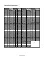
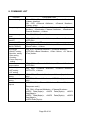
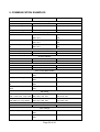
9000 Series Mixer/Amplifiers
RS-232C Protocol Manual
Ver.3.11 2006/11/14
Page 1 of 24
TABLE OF CONTENTS
Page#
1. SUMMARY…………………………………………………………………….... 3
2. SERIAL PORT SETTING…………………………………………………….... 3
3. COMMAND CONFIGURATION………………………………………………. 4
4. TRANSMISSION DATA AFTER COMMAND RECEPTION……………….. 4
5. CONTROL COMMAND AND SETTING VALUE……………………………. 5
5.1. Channel Fader Gain……………………………………………………………. 5
5.1.1. Channel Fader Gain - Position setting…………………………………… 5
5.1.2 Channel Fader Gain - Step Up/ Step Down…………………………….…. 7
5.2. Crosspoint Gain………………………………………………………………… 9
5.3. Preset Memory Recall…………………………………………………...…… 11
5.4. Channel ON/OFF…………………………………………………………….... 12
5.5. Power ON/OFF……………………………………………………………….... 12
5.6. Tone Control…………………………………………………………………….13
5.7. EQ Settings……………………………………………………………….……. 15
5.8. Loudness Compensation Settings………………………………………… 17
5.9. Filter Settings………………………………………………………………….. 18
5.10. Input Sensitivity Setting……………………………………………………. 19
5.11. Phantom Power ON/OFF Setting…………………………………………. 19
6. Channel Name Request…………………………………………………………………… 20
7. Speaker Preset Setting……………………………………………………………………. 21
8. COMMAND LIST…………………………………………………….………... 22
9. COMMUNICATION EXAMPLES…………………………………….………. 23
Page 2 of 24
1. SUMMARY
The RS-232C protocol described in this document is designed to be used to control the
9000 Series Amplifier from a PC and/or remote controller. This specification applies to the
9000 Series firmware version 3.10 or later.
Settings that can be controlled are as follows:
• Channel fader gain
• Crosspoint gain (Mixer mode only)
• Preset memory recall
• Channel ON/OFF
• Power ON/OFF
• Tone control (Bass/Treble)
• EQ settings (ON/OFF, Band number selection, Gain setting, Q setting, Center frequency setting)
• Loudness compensation settings
• Filter settings (High Pass Filter/Low Pass Filter)
• Input sensitivity setting
• Phantom power setting
Following values can be read from the 9000 Series Amplifier.
• Channel name
When connecting the PC and/or remote controller to the 9000 Series Amplifier using this protocol,
set the 9000 Series Amplifier’s RS-232C port as follows:
Bit rate: 9,600/19,200/38,400/57,600 bps (Select the band rate depending on the
remote controller to be connected.) (See; Operating instructions of the 9000
Series Amplifiers.)
COMMANDLIST, COMMUNICATION EXAMPLES and PARAMETER TABLES are
available at the end of each section of this document.
2. SERIAL PORT SETTING
• 9,600/19,200/38,400/57,600 bps, 8 bits, non-parity, stop bit: 1, non flow control
• Connector: D-sub 9 pins, straight cable
• Signal line: No.2=TX, No.3=RX, No.5=Ground
Page 3 of 24
3. COMMAND CONFIGURATION
•
•
Command
Data length (N)
Data 1
Data 2
is in the range of 80H to FFH.
Command
range
of 00H to 7FH.
Data
Data N
and
Data length
are in the
• Data length (N) refers to the length of the subsequent data of Data 1 to Data N.
• If received data contains more byte data than the Data length, these exceeding data are
abandoned.
• If a next command received contains byte data shorter than the Data length, the previous
command is abandoned.
4. TRANSMISSION DATA AFTER COMMAND RECEPTION
When normal data is received, the same data as the reception data is to be transmitted.
Example: 91H, 03H, 00H, 00H, 00H (Reception data)
91H, 03H, 00H, 00H, 00H (Transmission data)
When channel data is received and the data is outside of the range, the data is to be
inverted and transmitted.
Example: 91H, 03H, 00H, 08H, 00H (Reception data)
91H, 03H, 00H, 77H, 00H (Transmission data)
When abnormal data is received, the data is to be inverted and transmitted.
Example: 91H, 03H, 00H, 00H, 6AH (Reception data)
91H, 03H, 00H, 00H, 15H (Transmission data)
When data other than channel data is received and the data is outside of the range, no data
is transmitted.
Example: 91H, 03H, 05H, 00H, 6AH (Reception data)
No response
5. CONTROL COMMAND AND SETTING VALUE
Page 4 of 24
5.1. Channel Fader Gain
5.1.1. Channel Fader Gain - Position setting
Set the input and output channel fader gains to a fixed value position.
Note: Command cannot be received during power off.
9000Series Amplifier responds with the same data as that received.
91H, 03H, <Channel Attribute>, <Channel Number>, <Value>
<Channel Attribute>
00H: Input channel
01H: Output channel
<Channel Number>
00H - 07H (Input channel 1 - 8)
00H - 07H (Output channel 1 - 8)
<Value>
Position setting
00 – 7EH (-∞ to +10 dB)
See Channel Fader Gain - Position V/S Gain Table on the next page.
Example: Setting the fader gain of channel 1 to 0 dB
91H, 03H, 00H, 00H, 6AH
CHANNEL FADER GAIN - POSITION V/S GAIN TABLE
Page 5 of 24
HEX
Position
DEC
Gain
(dB)
HEX
Position
DEC
Gain
(dB)
HEX DEC
Position
Gain
(dB)
HEX
Position
DEC
Gain
(dB)
00H
0
-∞
22H
34
-36.0
44H
68
-19.0
66H
102
-2.0
01H
1
-70.0
23H
35
-35.5
45H
69
-18.5
67H
103
-1.5
02H
2
-68.0
24H
36
-35.0
46H
70
-18.0
68H
104
-1.0
03H
3
-66.0
25H
37
-34.5
47H
71
-17.5
69H
105
-0.5
04H
4
-64.0
26H
38
-34.0
48H
72
-17.0
6AH
106
0.0
05H
5
-62.0
27H
39
-33.5
49H
73
-16.5
6BH
107
+0.5
06H
6
-60.0
28H
40
-33.0
4AH
74
-16.0
6CH
108
+1.0
07H
7
-59.0
29H
41
-32.5
4BH
75
-15.5
6DH
109
+1.5
08H
8
-58.0
2AH
42
-32.0
4CH
76
-15.0
6EH
110
+2.0
09H
9
-57.0
2BH
43
-31.5
4DH
77
-14.5
6FH
111
+2.5
0AH
10
-56.0
2CH
44
-31.0
4EH
78
-14.0
70H
112
+3.0
0BH
11
-55.0
2DH
45
-30.5
4FH
79
-13.5
71H
113
+3.5
0CH
12
-54.0
2EH
46
-30.0
50H
80
-13.0
72H
114
+4.0
0DH
13
-53.0
2FH
47
-29.5
51H
81
-12.5
73H
115
+4.5
0EH
14
-52.0
30H
48
-29.0
52H
82
-12.0
74H
116
+5.0
0FH
15
-51.0
31H
49
-28.5
53H
83
-11.5
75H
117
+5.5
10H
16
-50.0
32H
50
-28.0
54H
84
-11.0
76H
118
+6.0
11H
17
-49.0
33H
51
-27.5
55H
85
-10.5
77H
119
+6.5
12H
18
-48.0
34H
52
-27.0
56H
86
-10.0
78H
120
+7.0
13H
19
-47.0
35H
53
-26.5
57H
87
-9.5
79H
121
+7.5
14H
20
-46.0
36H
54
-26.0
58H
88
-9.0
7AH
122
+8.0
15H
21
-45.0
37H
55
-25.5
59H
89
-8.5
7BH
123
+8.5
16H
22
-44.0
38H
56
-25.0
5AH
90
-8.0
7CH
124
+9.0
17H
23
-43.0
39H
57
-24.5
5BH
91
-7.5
7DH
125
+9.5
18H
24
-42.0
3AH
58
-24.0
5CH
92
-7.0
7EH
126
+10.0
19H
25
-41.0
3BH
59
-23.5
5DH
93
-6.5
1AH
26
-40.0
3CH
60
-23.0
5EH
94
-6.0
1BH
27
-39.5
3DH
61
-22.5
5FH
95
-5.5
1CH
28
-39.0
3EH
62
-22.0
60H
96
-5.0
1DH
29
-38.5
3FH
63
-21.5
61H
97
-4.5
1EH
30
-38.0
40H
64
-21.0
62H
98
-4.0
1FH
31
-37.5
41H
65
-20.5
63H
99
-3.5
20H
32
-37.0
42H
66
-20.0
64H
100
-3.0
21H
33
-36.5
43H
67
-19.5
65H
101
-2.5
Page 6 of 24
5.1.2 Channel Fader Gain - Step Up/ Step Down
Set the input and output channel gain positions by the number of steps.
Positions can be varied from the current status by the designated number of steps.
One position varies per step.
9000Series Amplifier responds with the same data as that received.
The 9000series Amplifier informs position values changed by Step Up or Down.
93H, 03H, <Channel Attribute>, <Channel Number>, <Step>
<Channel Attribute>
00H: Input channel
01H: Output channel
<Channel Number>
00H - 07H (Input channel 1 – 8)
00H - 07H (Output channel 1 – 8)
<Step>
UP: 41H – 5FH (1 – 31 step up); Example showing 0.5dB Step Up: 41H
Down: 61H - 7FH (1 – 31 step down); Example showing 0.5dB Step Down: 61H
Example showing 0.5dB up of Input Channel 1 fader gain
93H, 03H, 00H, 00H, 41H
See Channel Fader Gain – Step Up / Step Down Table on the next page.
Page 7 of 24
CHANNEL FADER GAIN – STEP UP / STEP DOWN TABLE
Step Up
HEX
DEC
41H
65
42H
66
43H
Gain (dB)
Step Down
Gain (dB)
HEX
DEC
+0.5 step
61H
97
-0.5 step
+1.0 step
62H
98
-1.0 step
67
+1.5 step
63H
99
-1.5 step
44H
68
+2.0 step
64H
100
-2.0 step
45H
69
+2.5 step
65H
101
-2.5 step
46H
70
+3.0 step
66H
102
-3.0 step
47H
71
+3.5 step
67H
103
-3.5 step
48H
72
+4.0 step
68H
104
-4.0 step
49H
73
+4.5 step
69H
105
-4.5 step
4AH
74
+5.0 step
6AH
106
-5.0 step
4BH
75
+5.5 step
6BH
107
-5.5 step
4CH
76
+6.0 step
6CH
108
-6.0 step
4DH
77
+6.5 step
6DH
109
-6.5 step
4EH
78
+7.0 step
6EH
110
-7.0 step
4FH
79
+7.5 step
6FH
111
-7.5 step
50H
80
+8.0 step
70H
112
-8.0 step
51H
81
+8.5 step
71H
113
-8.5 step
52H
82
+9.0 step
72H
114
-9.0 step
53H
83
+9.5 step
73H
115
-9.5 step
54H
84
+10.0 step
74H
116
-10.0 step
55H
85
+10.5 step
75H
117
-10.5 step
56H
86
+11.0 step
76H
118
-11.0 step
57H
87
+11.5 step
77H
119
-11.5 step
58H
88
+12.0 step
78H
120
-12.0 step
59H
89
+12.5 step
79H
121
-12.5 step
5AH
90
+13.0 step
7AH
122
-13.0 step
5BH
91
+13.5 step
7BH
123
-13.5 step
5CH
92
+14.0 step
7CH
124
-14.0 step
5DH
93
+14.5 step
7DH
125
-14.5 step
5EH
94
+15.0 step
7EH
126
-15.0 step
5FH
95
+15.5 step
7FH
127
-15.5 step
Page 8 of 24
5.2. Crosspoint Gain
Set the crosspoint switch gain. 9000Series Amplifier responds with the same data as that
received. This command is enabled when in the mixer mode only.
Note: Command cannot be received during power off.
95H, 05H, <Source Channel Attribute>, <Source Channel Number>, <Destination
Channel Attribute>, <Destination Channel Number>, <Value>
<Source Channel Attribute> 00H: Input channel
<Source Channel Number> 00H - 07H (Input channel 1 - 8)
<Destination Channel Attribute> 01H: Output channel
<Destination Channel Number> 00H – 07H (Output channel 1 - 8)
<Value>
00 - 51H: Gain Position (-∞ to +10.0 dB)
60 - 6FH: Position Down (1 – 16dB Step Down)
70 - 7FH: Position Up (1 – 16dB Step Up)
Example 1: Setting the crosspoint gain from Input Channel 1 to Output Channel 1 to a fixed
value of 0 dB
95H, 05H, 00H, 00H, 01H, 00H, 47H
Example 2: Increasing the crosspoint gain from Input Channel 1 to Output Channel 1 by
+3.0 dB steps
95H, 05H, 00H, 00H, 01H, 00H, 72H
See Crosspoint Gain Table on the next page.
Page 9 of 24
CROSSPOINT GAIN TABLE
value
HEX
DEC
Gain
(dB)
Value
HEX
DEC
Gain (dB)
Value
HEX
DEC
Gain (dB)
Value
HEX
DEC
Step Down
00H
0
-∞
22H
34
-37.0
44H
68
-3.0
65H
101
-6.0 step
01H
1
-70.0
23H
35
-36.0
45H
69
-2.0
66H
102
-7.0 step
02H
2
-69.0
24H
36
-35.0
46H
70
-1.0
67H
103
-8.0 step
03H
3
-68.0
25H
37
-34.0
47H
71
0.0
68H
104
-9.0 step
04H
4
-67.0
26H
38
-33.0
48H
72
1.0
69H
105
-10.0 step
05H
5
-66.0
27H
39
-32.0
49H
73
2.0
6AH
106
-11.0 step
06H
6
-65.0
28H
40
-31.0
4AH
74
3.0
6BH
107
-12.0 step
07H
7
-64.0
29H
41
-30.0
4BH
75
4.0
6CH
108
-13.0 step
08H
8
-63.0
2AH
42
-29.0
4CH
76
5.0
6DH
109
-14.0 step
09H
9
-62.0
2BH
43
-28.0
4DH
77
6.0
6EH
110
-15.0 step
0AH
10
-61.0
2CH
44
-27.0
4EH
78
7.0
6FH
111
-16.0 step
0BH
11
-60.0
2DH
45
-26.0
4FH
79
8.0
0CH
12
-59.0
2EH
46
-25.0
50H
80
9.0
70H
0DH
13
-58.0
2FH
47
-24.0
51H
81
10.0
71H
113
+2.0 step
0EH
14
-57.0
30H
48
-23.0
52H
82
reserved
72H
114
+3.0 step
0FH
15
-56.0
31H
49
-22.0
53H
83
reserved
73H
115
+4.0 step
10H
16
-55.0
32H
50
-21.0
54H
84
reserved
74H
116
+5.0 step
11H
17
-54.0
33H
51
-20.0
55H
85
reserved
75H
117
+6.0 step
12H
18
-53.0
34H
52
-19.0
56H
86
reserved
76H
118
+7.0 step
13H
19
-52.0
35H
53
-18.0
57H
87
reserved
77H
119
+8.0 step
14H
20
-51.0
36H
54
-17.0
58H
88
reserved
78H
120
+9.0 step
15H
21
-50.0
37H
55
-16.0
59H
89
reserved
79H
121
+10.0 step
16H
22
-49.0
38H
56
-15.0
5AH
90
reserved
7AH
122
+11.0 step
17H
23
-48.0
39H
57
-14.0
5BH
91
reserved
7BH
123
+12.0 step
18H
24
-47.0
3AH
58
-13.0
5CH
92
reserved
7CH
124
+13.0 step
19H
25
-46.0
3BH
59
-12.0
5DH
93
reserved
7DH
125
+14.0 step
1AH
26
-45.0
3CH
60
-11.0
5EH
94
reserved
7EH
126
+15.0 step
1BH
27
-44.0
3DH
61
-10.0
5FH
95
reserved
7FH
127
+16.0 step
1CH
28
-43.0
3EH
62
-9.0
1DH
29
-42.0
3FH
63
-8.0
60H
96
-1.0 step
1EH
30
-41.0
40H
64
-7.0
61H
97
-2.0 step
Value
Step Down
1FH
31
-40.0
41H
65
-6.0
62H
98
-3.0 step
20H
32
-39.0
42H
66
-5.0
63H
99
-4.0 step
21H
33
-38.0
43H
67
-4.0
64H
100
-5.0 step
Page 10 of 24
Value
112
Step Up
+1.0 step
5.3. Preset Memory Recall
Recalls any desired preset memories. 9000Series Amplifier responds with the same data
as that received.
Note:
Settings to be stored in preset memories are referred to as “SCENE” in mixer mode and
“EVENT” in matrix mode.
In 'Matrix mode', the command of 'EVENT end' is not provided.
Therefore, it is recommended to use ‘Preset memory recall’ command only for Mixer mode
‘SCENE’ activation.
In the case of using this command for ‘EVENT’ activation in Matrix mode, use the following
to end the ‘EVENT’ before activating other Events. Otherwise, EVENT priorities will not be
controlled properly.
To turn off the activation ‘EVENT’ in matrix mode, use one of the following procedures:
1) Use a busy signal (such as a contact closure) from external equipment (if available)
connecting to any control input terminal of The 9000 series Amplifier to sense busy
status using the busy input terminal setting.
2) Turn off the assigned input channel by using ‘Channel ON/OFF’ command (see
section 5.4 channel ON/OFF). Be sure to turn on the input channel again for next use.
In this case, all of the other EVENTS related to that input channel will also be turned
off.
Note: Preset Memory Recall command cannot be received during power off.
F1H, 02H, 00H, <Preset Number>
<Preset Number> 00H - 1FH: Preset Number 1 - 32
Note: During single channel operation or BGM/PAGE operation in matrix mode
00H - 07H: Preset Number 1 - 8
Example 1: Recalling Preset Memory 1
F1H, 02H, 00H, 00H
Example 2: Recalling Preset Memory 2
F1H, 02H, 00H, 01H
Page 11 of 24
5.4. Channel ON/OFF
This performs ON/OFF setting of the Input or Output channel. 9000Series Amplifier
responds with the same data as that received.
92H, 03H, <Channel Attribute>, <Channel Number>, <ON/OFF>
<Channel Attribute>
00H: Input channel
01H: Output channel
<Channel Number>
00H - 07H (Input channel 1 - 8)
00H - 07H (Output channel 1 - 8)
<ON/OFF>
00H: Channel OFF
01H: Channel ON
Example 1: Setting the Input Channel 1 to ON
92H, 03H, 00H, 00H, 01H
Example 2: Setting the Input Channel 1 to OFF
92H, 03H, 00H, 00H, 00H
5.5. Power ON/OFF
This command performs ON/OFF setting of the power switch of the 9000 Series Amplifier.
9000Series Amplifier responds with the same data as that received.
F4H, 01H, <ON/OFF>
<ON/OFF>
00H: Power OFF
01H: Power ON
Example 1: Setting the power switch to OFF.
F4H, 01H, 00H
Example 2: Setting the power switch to ON.
F4H, 01H, 01H
Page 12 of 24
5.6. Tone Control
Performs Bass and Treble gain settings of the input/output channels. 9000Series Amplifier
responds with the same data as that received..
Note: Command cannot be received during power off.
AAH, 04H, <Channel Attribute>, <Channel Number>, <Bass/Treble>, <Value>
<Channel Attribute>
00H: Input channel
01H: Output channel
<Channel Number>
00H - 07H (Input channel 1 - 8)
00H - 07H (Output channel 1 - 8)
<Bass/Treble>
00H: Bass Gain
01H: Treble Gain
<Value>
00 - 18H: Gain Position (-12 to +12dB)
21 - 2CH: Position Down (1 –12dB Step Down)
2D - 38H: Position Up (1 – 12dB Step Up)
Example 1: Setting the Input Channel 1 Bass Gain fixed value to 0 dB.
AAH, 04H, 00H, 00H, 00H, 0CH
Example 2: Increasing Input Channel 1 Bass Gain by +3.0 dB step increments.
AAH, 04H, 00H, 00H, 00H, 2FH
See Tone Control Gain Position Table on the next page.
Page 13 of 24
TONE CONTROL GAIN POSITION TABLE
Value
HEX
Gain (dB)
DEC
Value
HEX
DEC
Gain (dB)
00H
0
-12.0
0DH
13
+1.0
01H
1
-11.0
0EH
14
+2.0
02H
2
-10.0
0FH
15
+3.0
03H
3
-9.0
10H
16
+4.0
04H
4
-8.0
11H
17
+5.0
05H
5
-7.0
12H
18
+6.0
06H
6
-6.0
13H
19
+7.0
07H
7
-5.0
14H
20
+8.0
08H
8
-4.0
15H
21
+9.0
09H
9
-3.0
16H
22
+10.0
0AH
10
-2.0
17H
23
+11.0
0BH
11
-1.0
18H
24
+12.0
0CH
12
0
Value
HEX
DEC
21H
33
22H
34
Step Down
Value
Step Up
HEX
DEC
-1.0 step
2DH
45
+1.0 step
-2.0 step
2EH
46
+2.0 step
23H
35
-3.0 step
2FH
47
+3.0 step
24H
36
-4.0 step
30H
48
+4.0 step
25H
37
-5.0 step
31H
49
+5.0 step
26H
38
-6.0 step
32H
50
+6.0 step
27H
39
-7.0 step
33H
51
+7.0 step
28H
40
-8.0 step
34H
52
+8.0 step
29H
41
-9.0 step
35H
53
+9.0 step
2AH
42
-10.0 step
36H
54
+10.0 step
2BH
43
-11.0 step
37H
55
+11.0 step
2CH
44
-12.0 step
38H
56
+12.0 step
Note: 19H – 20H are deemed to be reserved.
Page 14 of 24
5.7. EQ Settings
Perform EQ settings (ON/OFF, Band number, Gain, Q and Center frequency) of the
input/output channels. 9000Series Amplifier responds with the same data as that received.
Band number, Gain, Q, and Center frequency cannot be received when EQ is set to OFF.
They can be valid only when EQ is set to ON.
Note: Command cannot be received during power off.
A1H, 07H, <Channel Attribute>, <Channel Number>, <OFF/ON>, <Band Number>,
<Gain Value>, <Q Value>, <Freq Value>
<Channel Attribute>
00H: Input channel
01H: Output channel
<Channel Number>
00H - 07H (Input channel 1 - 8)
00H - 07H (Output channel 1 - 8)
<OFF/ON>
00H: EQ OFF
01H: EQ ON
<Filter Number>
00H - 09H: Filter 01 - 10
<Gain Value>
EQ-GAIN TABLE
Value
Gain (dB)
HEX
DEC
00H
0
01H
Value
Gain (dB)
HEX
DEC
-12
0DH
13
+1
1
-11
0EH
14
+2
02H
2
-10
0FH
15
+3
03H
3
-9
10H
16
+4
04H
4
-8
11H
17
+5
05H
5
-7
12H
18
+6
06H
6
-6
13H
19
+7
07H
7
-5
14H
20
+8
08H
8
-4
15H
21
+9
09H
9
-3
16H
22
+10
0AH
10
-2
17H
23
+11
0BH
11
-1
18H
24
+12
0CH
12
0
Note: If testing using Hyperterminal HEX value 0DH may incorrectly translate and will not
work. But when used in other applications using the HEX 0DH will work.
Page 15 of 24
<Q Value>
EQ-Q TABLE
Value
Q
HEX
DEC
00H
0
0.3
01H
1
0.5
02H
2
0.7
03H
3
1
04H
4
1.5
05H
5
2
06H
6
3
07H
7
5
<Freq Value>
EQ-FREQUENCY TABLE
Value
Freq (Hz)
HEX
DEC
00H
0
01H
Value
Freq (Hz)
HEX
DEC
20
11H
13
1k
1
25
12H
14
1.25k
02H
2
31.5
13H
15
1.6k
03H
3
40
14H
16
2k
04H
4
50
15H
17
2.5k
05H
5
63
16H
18
3.15k
06H
6
80
17H
19
4k
07H
7
100
18H
20
5k
08H
8
125
19H
21
6.3k
09H
9
160
1AH
22
8k
0AH
10
200
1BH
23
10k
0BH
11
250
1CH
24
12.5k
0CH
12
315
1DH
25
16k
0DH
13
400
1EH
26
20k
0EH
14
500
0FH
15
630
10H
16
800
Example:
Setting the Input Channel 1’s EQ to ON, Band No. to 1, Gain value to +2 dB, Q
value to 0.7 and Center frequency to 40 Hz.
A1H, 07H, 00H, 00H, 01H, 00H, 0EH, 02H, 03H
Page 16 of 24
5.8. Loudness Compensation Settings
Perform loudness compensation settings of the Input / Output channels. 9000Series
Amplifier responds with the same data as that received.
Note: Command cannot be received during power off.
ABH, 03H, <Channel Attribute>, <Channel Number>, <OFF/ON>
<Channel Attribute>
00H: Input channel
01H: Output channel
<Channel Number>
00H - 07H (Input channel 1 - 8)
00H - 07H (Output channel 1 - 8)
<OFF/ON>
00H: Loudness OFF
01H: Loudness ON
Example: Setting the loudness compensation of Output Channel 2 to ON
ABH, 03H, 01H, 01H, 01H
Page 17 of 24
5.9. Filter Settings
Perform Filter (HPF/LPF) settings of Input / Output channels. 9000Series Amplifier
responds with the same data as that received.
Note: Command cannot be received during power off.
A2H, 04H, <Channel Attribute>, <Channel Number>, <HPF/LPF>, <Value>
<Channel Attribute>
00H: Input channel
01H: Output channel
<Channel Number>
00H - 07H (Input channel 1 - 8)
00H - 07H (Output channel 1 - 8)
<HPF/LPF>
00H: High Pass Filter
01H: Low Pass Filter
<Frequency Value>
HIGH PASS FILTER
LOW PASS FILTER
TABLE – 00H
Value
TABLE – 01H
HPF (Hz)
HEX
DEC
00H
0
Value
LPF (Hz)
OFF
HEX
DEC
0
4k
01H
1
20
00H
02H
2
25
01H
1
5k
03H
3
31.5
02H
2
6.3k
04H
4
40
03H
3
8k
4
10k
05H
5
50
04H
06H
6
63
05H
5
12.5k
07H
7
80
06H
6
16k
08H
8
100
07H
7
20k
08H
8
OFF
09H
9
125
0AH
10
160
0BH
11
200
0CH
12
250
0DH
13
315
0EH
14
400
Example: Setting the Input Channel 3’s High Pass Filter to 31.5 Hz.
A2H, 04H, 00H, 02H, 00H, 03H
Page 18 of 24
5.10. Input Sensitivity Setting
Performs input sensitivity setting of Input channel. 9000Series Amplifier responds with the
same data as that received. Input sensitivity setting is enabled only for the channel on
which the D-001T or AN-001T is used.
Note: Command cannot be received during power off.
ACH, 02H, <Channel Number>, <Value>
<Channel Number>
00H - 07H (Input channel 1 - 8)
<Value >
INPUT SENSITIVITY TABLE
Value
HEX
DEC
Sense
(dB)
Value
HEX
DEC
Sense
(dB)
00H
0
-10
05H
5
-42
01H
1
-18
06H
6
-48
02H
2
-24
07H
7
-54
03H
3
-30
08H
8
-60
04H
4
-36
Example: Setting the input sensitivity of Input Channel 5 to –24 dB.
ACH, 02H, 04H, 02H
5.11. Phantom Power ON/OFF Setting
Sets the phantom power of Input channel to ON or OFF. 9000Series Amplifier responds
with the same data as that received.
Note: Command cannot be received during power off.
87H, 02H, <Channel Number>, <OFF/ON>
<Channel Number>
00H - 07H (Input channel 1 - 8)
<OFF/ON>
00H: PHANTOM OFF
01H: PHANTOM ON
Example: Setting the phantom power of Input Channel 1 to ON.
87H, 02H, 00H, 01H
Page 19 of 24
6. Channel Name Request
Reads input and output channels’ names. The 9000 Series Amplifier responds with the
channel name to this command.
F0H, 03H, 40H, <Channel Attribute>, <Channel Number>
<Channel Attribute>
00H: Input channel
01H: Output channel
<Channel Number>
00H - 07H (Input channel 1 - 8)
00H - 07H (Output channel 1 - 8)
Example: Acquiring the Input Channel 1’s name.
F0H, 03H, 40H, 00H, 00H
Response data are provided below.
C0H, 09H, <Channel Attribute>, <Channel Number>,
<ASCII Data (1byte)>, <ASCII Data (2byte)>, <ASCII Data (3byte)>,
<ASCII Data (4byte)>, <ASCII Data (5byte)>, <ASCII Data (6byte)>,
<ASCII Date (7byte)>
Example: Responding with the Input Channel 1’s name “INPUT1.”
C0H, 09H, 00H, 00H, 49H, 4EH, 50H, 55H, 54H, 31H, 00H
Table below shows ASCII codes used for Names.
Numeric
Alphabetic
Symbol
0
1
2
3
4
5
6
7
8
9
30H
31H
32H
33H
34H
35H
36H
37H
38H
39H
A
B
C
D
E
F
G
H
I
J
41H
42H
43H
44H
45H
46H
47H
48H
49H
4AH
K
L
M
N
O
P
Q
R
S
T
4BH
4CH
4DH
4EH
4FH
50H
51H
52H
53H
54H
U
V
W
X
Y
Z
55H
56H
57H
58H
59H
5AH
“
$
&
>
(
)
*
+
-
/
22H
24H
26H
27H
28H
29H
2AH
2BH
2DH
2FH
<
=
>
?
[
¥
]
_
3CH
3DH
3EH
3FH
5BH
5CH
5DH
5FH
Page 20 of 24
7. Speaker Preset Setting
Recalls speaker EQ preset values for specific TOA model speakers. 9000Series Amplifier
responds with the same data as that received.
Note: Command cannot be received during power off.
ADH, 02H, <Output Channel Number>, <Value>
<Output Channel Number>
00H - 07H (Output channel 1 - 8)
<Value >
SPEAKER PRESET TABLE
Value
Sense (dB)
Value
HEX
Sense (dB)
HEX
DEC
DEC
00H
0
ALL FLAT
08H
8
H-3 SUB WOOFER
01H
1
F-122
09H
9
HB-1
02H
2
F-122 SUB WOOFER
0AH
10
FB-100
03H
3
H-1
0BH
11
SW FOR F-122
04H
4
H-1 SUB WOOFER
0CH
12
SR-S4 SINGLE
05H
5
H-2
0DH
13
HX-5_E
06H
6
H-2 SUB WOOFER
0EH
14
HX-5_E_LOCUT
07H
7
H-3
0FH
15
FB-120
Page 21 of 24
8. COMMAND LIST
Function
Channel fader gain
Crosspoint gain
Preset memory
recall
Channel
ON/OFF
Power ON/OFF
Tone control
(BASS/TREBLE)
EQ settings
- ON/OFF setting
- Band No, setting
- Gain setting
- Q setting
- Center frequency
setting
Loudness
compensation
Filter setting
- HPF setting
- LPF setting
Input sensitivity
setting
Phantom power
setting
Channel name
request
Command Code
91H, 03H, <Channel Attribute>, <Channel Number>,
<Value> (position)
93H, 03H, <Channel Attribute>, <Channel Number>,
<Value> (step)
95H, 05H, <Source Channel Attribute>, <Source Channel
Number>, <Destination Channel Attribute>, <Destination
Channel Number>, <Value>
F1H, 02H, 00H, <Preset Number>
92H, 03H, <Channel Attribute>, <Channel Number>,
<OFF/ON>
F4H, 01H, <ON/OFF>
AAH, 04H, <Channel Attribute>, <Channel Number>,
<Bass/Treble>, <Value>
A1H, 07H, <Channel Attribute>, <Channel Number>,
<OFF/ON>,<Band Number>, <Gain Value>, <Q Value>,
<Freq Value>
ABH, 03H, <Channel Attribute>, <Channel Number>,
<OFF/ON>
A2H, 04H, <Channel Attribute>, <Channel Number>,
<HPF/LPF>, <Value>
ACH, 02H, <Channel Number>, <Value>: (Input channel
only)
87H, 02H, <Channel Number>, <OFF/ON>: (Input channel
only)
F0H, 03H, 40H, <Channel Attribute>, <Channel Number>
[Response code]
C0H, 09H, <Channel Attribute>, <Channel Number>,
<ASCII Data(1byte)>, <ASCII Data(2byte)>, <ASCII
Data(3byte)>,
<ASCII Data(4byte)>, <ASCII Data(5byte)>, <ASCII
Data(6byte)>,
<ASCII Data(7byte)>
Page 22 of 24
9. COMMUNICATION EXAMPLES
Command
Controller
A-9000 Response
Channel fader gain
Input ch1 Fader gain=0dB
91H, 03H, 00H, 00H, 6AH
91H, 03H, 00H, 00H, 6AH
Input ch1 Fader gain 1 step
up
93H, 03H, 00H, 00H, 41H
93H, 03H, 00H, 00H, 41H
Output ch1 Fader gain=-∞dB
91H, 03H, 01H, 00H, 00H
91H, 03H, 01H, 00H, 00H
Input ch1->Output ch1 0dB
95H, 05H, 00H, 00H, 01H,
00H, 47H
95H, 05H, 00H, 00H, 01H, 00H,
47H
Input ch3->Output ch5 -20dB
95H, 05H, 00H, 02H, 01H,
04H, 33H
95H, 05H, 00H, 02H, 01H, 04H,
33H
Input ch4->Output ch1 1 step
up
95H, 05H, 00H, 03H, 01H,
00H, 70H
95H, 05H, 00H, 03H, 01H, 00H,
70H
Event1 Start (Matrix)
F1H, 02H, 00H, 00H
F1H, 02H, 00H, 00H
Scene5 Load (Mixer)
F1H, 02H, 00H, 04H
F1H, 02H, 00H, 04H
Crosspoint gain
Preset memory recall
Channel ON/OFF
Input ch1 OFF
92H, 03H, 00H, 00H, 00H
92H, 03H, 00H, 00H, 00H
Output ch2 ON
92H, 03H, 01H, 01H, 01H
92H, 03H, 01H, 01H, 01H
Power ON/OFF
Power OFF
F4H, 01H, 00H
F4H, 01H, 00H
Power ON
F4H, 01H, 01H
F4H, 01H, 01H
Input ch1 Bass gain -5dB
AAH, 04H, 00H, 00H, 00H,
07H
AAH, 04H, 00H, 00H, 00H, 07H
Output ch3 Treble gain 0dB
AAH, 04H, 01H, 02H, 01H,
0CH
AAH, 04H, 01H, 02H, 01H, 0CH
Input ch2 Treble gain 2 step
up
AAH, 04H, 00H, 01H, 01H,
2EH
AAH, 04H, 00H, 01H, 01H, 2EH
Output ch1 Bass gain 1 step
down
AAH, 04H, 01H, 00H, 00H,
21H
AAH, 04H, 01H, 00H, 00H, 21H
Tone control (Bass/Treble)
EQ setting
Input ch1 EQ ON, Band01,
Gain +1dB, Q 0.5, Freq 40Hz
A1H, 07H, 00H, 00H, 01H,
00H, 0DH, 01H, 03H
A1H, 07H, 00H, 00H, 01H, 00H,
0DH, 01H, 03H
Output ch3 EQ ON, Band05,
Gain 0dB, Q 3, Freq 200Hz
A1H, 07H, 01H, 02H, 01H,
04H, 0CH, 06H, 0AH
A1H, 07H, 01H, 02H, 01H, 04H,
0CH, 06H, 0AH
Loudness compensation settings
Input ch4 Loudness ON
ABH, 03H, 00H, 03H, 01H
ABH, 03H, 00H, 03H, 01H
Filter settings
Input ch2 Hpf 31.5Hz
A2H, 04H, 00H, 01H, 00H,
03H
A2H, 04H, 00H, 01H, 00H, 03H
Output ch1 Lpf 6.3kHz
A2H, 04H, 01H, 00H, 01H,
02H
A2H, 04H, 01H, 00H, 01H, 02H
Page 23 of 24
Command
Controller
A-9000 Response
Input sensitivity setting
Input ch1 Insense -24dB
ACH, 02H, 00H, 02H
ACH, 02H, 00H, 02H
Speaker preset setting
Output ch2 SpPreset F-122
ADH, 02H, 01H, 01H
ADH, 02H, 01H, 01H
Phantom power setting
Input ch3 Phantom ON
87H, 02H, 02H, 01H
87H, 02H, 02H, 01H
Channel name recall
Input ch1 Name “INPUT1”
F0H, 03H, 40H, 00H, 00H
Page 24 of 24
C0H, 09H, 00H, 00H,
49H, 4EH, 50H,
55H, 54H, 31H, 00H