1
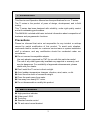
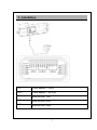
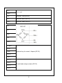
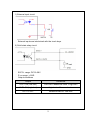
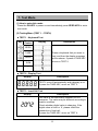
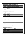
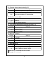
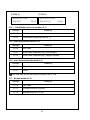
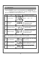
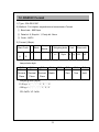
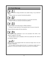
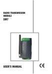
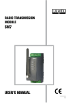
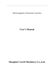
TI-2300 / 3000
VER 101
WIDE INDICATOR
USER’S MANUAL
www.tmteng.com
1
INDEX
1. Introduction ................................................................................ 3
2. Main Features ............................................................................ 3
3. Technical Specifications ........................................................ 4
4. Description of Panels and Symbols ................................. 6
5. Installation ................................................................................... 7
6. General Function .................................................................... 10
7. Test Mode ................................................................................. 11
8. Setting Mode ........................................................................... 13
9. Calibration ................................................................................. 18
10. Infrared Remote Controller ............................................. 19
11. Wireless Specifications ...................................................... 20
12. RS232C Format ..................................................................... 21
13. Real Time Clock .................................................................... 22
14. Check Message .................................................................... 23
2
1. Introduction
This Service and Operation Manual are the specifications for our TI series.
The TI series is the product of years of design, development, and in-field
testing.
This TI series has been designed with reliability, under rigid quality control
and with outstanding performance.
This MANUAL included with basic technical information about composition of
hardware and programmatic functions.
Precautions
Please be informed that we’re not responsible for any incident or mishap
caused by partial modification of this product. To avoid such situation,
customers need to contact our customer service team or system installation
staff in advance, and any modification should be conducted under our
surveillance.
◆ Do not connect incompatible adaptor.
Use only adaptor approved by TMT for use with this particular model.
The use of any other types may invalidate any approval or warranty, and
may be dangerous. For availability of approved enhancements, please
check with your dealer.
◆ Don’t install the TI series in direct sunlight.
◆ Avoid sudden temperature changes, vibration, wind, water, or dirt.
◆ Avoid from the shock of excessive weight.
◆ Place the scale away from water.
◆ Use away from heavy R.F noise.
◆ Do not disassemble or modify this product.
2. Main Features
◆
◆
◆
◆
◆
High-precision indicator
Water proof: IP65
Touch key
Standard remote control
Tilt and swivel mount bracket
3
3. Technical Specifications
◆ Specifications
Display
TI-2300: 2.3inch 5 FND / TI-3000: 3inch 5 FND
Display lamp
Zero, Tare, Hold, Stable, Power
Touch key
Zero, Tare, Hold, On/Off
Case material
Engineering plastic
Load Cell Excitation
DC 5V, 300mA (up to 8 load cell)
Input sensitivity
0.2uV/D
Input signal range
0~39mV
Non linearity
<±0.0015% of FSR max
External resolution
Up to 100,000 counts
Output data rate
4.7 to 200 measurements per second
Temperature range
-20℃ ~ 60℃
Product weight
TI-2300: 1.2kg / TI-3000: 2.2kg
Power
12V
Parts
Power adaptor, IR remote controller
OP-01
RS232C, RTC(Real time clock),
2solid state relays and 4inputs
OP-02
Use the vehicle power (12~24V )
OP-03
ZigBee wireless
1A
4
◆ Dimensions
1) TI-2300
2) TI-3000
5
4. Description of Panels and Symbols
◆ Display
Displays weight or messages
STABLE
Indicates that the weight to be in stable condition
ZERO
Indicates that scale is stable and at zero
TARE
Indicates that scale is currently using a tare
HOLD
Indicates that the HOLD feature has been activated
◆ Keys
Power Use to turn on/off.
Zero
Return the display to 0.
Tare
Use to weigh with tare weight.
Hold
Use to weigh unstable things.
6
5. Installation
12V
Power adaptor + (RED)
GND
Power adaptor – (BLACK)
TX3
Extra RS232C TXD
RX3
Extra RS232C RXD
GND
Extra RS232C GND
7
RX1
GND
Not used
TX2
RS232C TXD (OP-01)
RX2
RS232C RXD (OP-01)
GND
RS232C GND (OP-01)
EX+
EXSIG+
SIGGND
POWER
ZERO
TARE
External key 4 contact / 4inputs (OP-01)
HOLD
GND
EVCC+
OUT1
EVCC+
2 solid state relays contact (OP-01)
OUT2
8
1) External input circuit
※ External inputs are interlocked with the touch keys.
2) Solid state relay circuit
※ EVCC+ range: DC12~28V
※ R load range: > 2KΩ
※ Output conditions
Output
Conditions
OUT2 ON (low limit)
Low limit< Measured value ≤ High limit
OUT1 ON (high limit)
High limit < Measured value
OUT1,2 OFF
Measured value ≤ Low limit
9
6. General Function
(1) Zero Function
Use to correct drifted zero value when the scale is unloaded, and motion is
not detected. This function works when ZERO KEY is pressed, and the
ZERO LAMP is on.
(2) Setting Tare Weight Function
Press the TARE KEY. Then, the scale will memorize the weight of the tare
and will display zero value “0”kg. The TARE LAMP will be on.
To escape this function, remove everything from the scale, and press the
TARE KEY. Then, the TARE LAMP will be off and this function is
terminated.
* Note : The sum weight of the tare and any item on a scale cannot exceed
maximum capacity.
(3) Hold Function
Automatic Hold Function
(This function works whenever the scale weighs moving things.)
■ Press HOLD KEY when the scale is empty (Initial Zero State).
■ The weight display will indicate AH ON. HOLD LAMP is on.
■ After loading a thing, if the weight turns stable then, a display shows
----- and average weight will appear.
■ The weight of a loaded thing is displayed.
■ To escape the automatic hold mode, when zero point is on, press HOLD
KEY. Then, the message of AHOFF is displayed and HOLD LAMP is off
and normal weighing mode is reverted.
Manual Hold Function
(Only this function operates when you press a HOLD KEY)
■ Press HOLD KEY loading a thing.
■ This message of HOLD is displayed and sequentially the message of
----- is shown with appearing the average weight.
■ The weight of a loaded thing is displayed.
■ To escape the manual hold mode, remove everything from a hook, or press
the HOLD KEY. Then, HOLD LAMP will be off and the scale changes from
a hold mode to a normal mode.
10
7. Test Mode
(1) How to enter this mode
Press the ON KEY to power on and immediately press ZERO KEY to enter
test mode.
(2) Testing Menu (TEST 1 – TEST4)
■ TEST 1 : Keyboard Test
Key
Remote
Control
Display
Description
ZERO
TARE
Press a keyboard that you want to
test, and then the display message
will be shown. If press a TARE KEY,
move on TEST 2.
HOLD
SUM
*
■ TEST 2 : Display Test
Display
Description
TEST 2 runs off automatically and a display is on.
If press the TARE KEY, move on TEST 3.
■ TEST 3 : Load Cell Test
Display
Description
2072
The value is the conversion constant for A/D
converter. The value may be different according to
scale’s condition.
Check whether digital value is changing. If the
digital value is fixed or ‘0’, please check the
connection of load cell.
If press the TARE KEY, move on TEST 4.
11
■ TEST 4 : Solid state relay output test
Display
OUT-0
Description
ZERO KEY: All outputs are turned off.
HOLD KEY: Increase the output number & this
output is turned on.
If press the TARE KEY, move on weighing mode.
12
8. Setting Mode
(1) How to enter this mode
Press the ON KEY to power on and immediately press TARE KEY to enter
setting mode.
(2) Keyboard
■ ZERO KEY : Use to set up an initial zero value (0).
(F4,F18,F19: Used to move the input value to the left or right by one place)
■ HOLD KEY : Use to add a value of “1” from existing value.
■ TARE KEY : Use to save an inputting value and to move on next menu.
(3) Menus
F01 : Assignment of weight variation rate (1~9)
Settings
Meaning
F01-1
Indicating rate of weight is fast.
F01-5
Indicating rate of weight is moderate.
F01-9
Indicating rate of weight is very slow.
F02 : Weight backup (0,1)
Settings
Meaning
F02-0
Not used
F02-1
Used
F03 : Assignment of Stabilization speed (1~9)
Value
F03-1
F03-5
F03-9
Description
Recognized as stable for change under half graduation for
0.5 sec.
Recognized as stable for change under half graduation for
2.5 sec.
Recognized as stable for change under half graduation for
4.5 sec.
13
F04 : Assignment of Automatic zero calibration (0~99)
Settings
Meaning
F4-00
Automatic zero calibration is not carried out.
F4-23
Automatic zero is calibrated for change under 1 gradation
for 3 sec.
F4-99
Automatic zero is calibrated for change under 4.5 gradation
for 9 sec.
F05 : Assignment of Hold speed (1~9)
Settings
Meaning
F05-1
Very fast
F05-5
Normal
F05-9
Very slow
F06 : Auto hold function (0,1)
Settings
Meaning
F06-0
Manual
F06-1
Automatic
F07 : Initialization of hold value (1~9)
Settings
Meaning
F07-1
In the zero weight
F07-5
In the 5 division weight
F07-9
In the 9 division weight
F08 : PC/Printer connection (0~2)
Settings
Meaning
F08-0
Wireless
F08-1
RS232C
F08-2
Wireless & RS232C
14
F09 : Function * key of remote controller (0~2)
Settings
Meaning
F09-0
Operation is equal to the * key of the master
F09-1
Send data command key (Print format)
F09-2
Send data command key (18bytes format)
F10 : Hold key function (0,1)
Settings
Meaning
F10-0
Hold key
F10-1
* key (Remote controller)
F11 : Item number (Identification number of each Item) (0~9)
Settings
Meaning
F11-0
Item No.0 (0x01)
F11-5
Item No.5 (0x05)
F11-9
Item No.9 (0x09)
F12 : Print line feed (0~9)
Settings
Meaning
F12-0
1 line feed
F12-5
6 line feed
F12-9
10 line feed
F13 : Print form (0~2)
Settings
Meaning
F13-0
Form 0 (weigh No., Item No., weight)
F13-1
Form 1 (Serial No., Item No., weight)
When the F09-1 is selected, this form is printed.
The weigh No. is not saved.
15
[FORM 0]
[FORM 1]
2013.10.13 12:00
001, ID_9,
2013.10.13 12:00
25 kg
SN_02, ID_9,
25 kg
F14 : : Initialization of serial number (0,1)
Settings
Meaning
F14-0
Maintain current number
F14-1
Initialization (starting from No.1)
F15 : Auto transmit at stable (0~2)
Settings
Meaning
F15-0
Not used
F15-1
Send data command key (Print format)
F15-2
Send data command key (18bytes format)
F16 : Auto transmit at data hold (0,1)
Settings
Meaning
F16-0
Not used
F16-1
Used
The hold data will be sent by according to set in F08.
F17 : Stream mode (0~2)
Settings
Meaning
F17-0
Not used
F17-1
Stream mode for RS232C
F17-2
Stream mode for TF200
16
F18 : Setting low limit (not included weighing points)
Settings
200
Meaning
20.0kg (In case of one decimal point)
Select a digit place to be inputted with ZERO KEY.
Input a figure with HOLD KEY. Press TARE KEY to enter the value.
F19 : Setting high limit (not included weighing points)
Settings
500
Meaning
50.0kg (In case of one decimal point)
Select a digit place to be inputted with ZERO KEY.
Input a figure with HOLD KEY. Press TARE KEY to enter the value.
17
9. Calibration
Press the ON KEY to power on and immediately press HOLDE KEY until
‘-----’ is displayed and press ZERO KEY. And then ‘G-CAL’ is displayed
and press TARE KEY to enter calibration mode.
No
Title
Display
Operation & Description
☞
☞
1
Show version
2
Maximum
capacity
increment of input value
increment of digit
shift next menu
3
Minimum division
increase /
decrease
shift next menu
4
Balance weight
increment of input value
increment of digit
shift next menu
It is recommendable to calibrate using a balance weight which weights
50% of the maximum capacity or more in terms of linearity.
5
Zero calibration
6
Span calibration
7
Calibration finish
Check unload the tray and
press
key
Load the weight which was set
in point 4 and press
key
Unload the tray and press
key
18
10. Infrared Remote Controller
(1) How to use
■ OFF KEY : Use to power on/off the TI series
■ ZERO KEY : Same as keyboard of TI series
■ TARE KEY : Same as keyboard of TI series
■ HOLD KEY : Same as keyboard of TI series
■ * KEY (CLEAR) : Refer to F09.
■ SUM KEY : Use to add weights.
If press a SUM KEY, the sum of weights is displayed.
After that, about 2 sec later, a weighing mode is
reverted.
Weight of less than 5 digits is not summed.
Maximum of sum weights is 99999, and if it exceeds
the weights is initialized to 0.
(2) Specification
List
Description
Available Distance
6 m ~ 10 m
Available Angle
60°
Power
3V (1.5V AA 2pcs)
19
11. Wireless Specifications
RF frequency range
2400 ~ 2483.5 MHz
Output power
Max. 4dBm
Channel width
2 MHz
Frequency offset
< ±30ppm
Transmit data rate
250Kbps,500Kbps
Receiver sensitivity
-99dBm (PER <1%)
Maximum input level
0dBm
RF In/out impedance
50 ohm (TXRF, RXRF)
Spurious(2nd harmonics)
< -30dBm
Radio link effective range
Approx. 100M (Open space)
20
12. RS232C Format
1) Type : EIA-RS-232C
2) Method : Full-duplex, asynchronous transmission Format
① Baud rate : 9600 bps
② Data bit: 8, Stop bit: 1, Parity bit: None
③ Code : ASCII
3) Format (18byte)
Start Code
S
T
U
S
Lamp
Blank
Weighing data
Status
,
,
+/-
7byte
Unit
Stop code
k
CR
g
LF
※ Start code : ST (Stable) / US (Unstable)
※ Lamp status byte
Bit7
One
Bit6
Two
Bit5
Three
Bit4
Decimal
Decimal
Decimal
Stable
Place
Place
Place
※ Weighing data (8byte)
13.5 kg = '+', ' ', ' ', ' ', '1', '3', '.', '5'
-135 kg = '-', ' ', ' ', ' ', ' ', '1', '3', '5'
※ CR: 0x0D / LF: 0x0A
21
Bit3
Bit2
Bit1
Bit0
Zero
Tare
Hold
13. Real Time Clock
(1) How to enter this mode
Press the ON KEY to power on and immediately press HOLD KEY. And
press the TARE KEY again.
(2) Keyboard
: Used to increase the setting constant one by one.
: Used to move the input value to the left or right by one place.
: Used to save the value and to move next menu.
(3) Menu
No
Display
Description
1
YEAR
2013
Modify the year
2
DATE
10 13
Modify the date
3
TIME
18 00
Modify the time
4
END
The end
22
14. Check Message
Data in an internal storage allocation are erased owing to any electronic
impact.
☞ Please contact us to resolve this technical problem.
Something wrong in a Load cell connection or in an serial connection.
☞ Please contact us to resolve this technical problem.
Load cell output is too small (large) at SPAN calibration.
☞ Setting of current resolution is not possible due to the error in load cell.
Proceed calibration again with less resolution.
The weight for span calibration is set to be exceeded 10%~100% of the
maximum capacity of the scale.
☞ Set the weight for span calibration in CAL3 to be within the 10%~100% of
the maximum capacity.
When a thing is over-weighed within the maximum weight value, the error
message is displayed.
☞ Do not weigh the thing whose the limit of a maximum weight value is
exceeded. If a load cell is broken, then the load cell has to be replaced.
23
MEMO
24