1
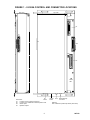
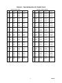
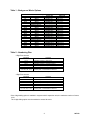
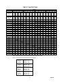
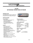
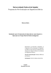
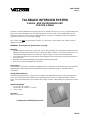
VSP-V-2925A
Issue 3
TALKBACK INTERCOM SYSTEM
V-2925A - ADD ON EXPANSION UNIT
FOR THE V-2924A
The basic V-2924A Talkback Intercom System provides 24 stations with one-way, two-way, group call and all call
pages. The V-2925A Expansion Unit is an add on unit for the V-2924A. Each V-2925A Expansion Unit will
expand the V-2924A by twenty-four (24) additional stations. Up to three (3) Expansion Units can be added to a
system for a total of 48, 72, or 96 zones of paging.
The V-2925A can ONLY be used with the V-2924A. If you have the V-2924 model, please contact Technical
Support for assistance.
WARNING: Disconnect main power before servicing.
Mounting
• Plug the Expansion Unit into the Control Unit. For the first Expansion Unit, insert the P1 connector from the
Expansion Unit into the P8 connector on the Control Unit (Refer to Figure 1 for location of connectors). (For
each additional Expansion Unit, insert P2 into P1 – Refer to Figure 1 of the Control Unit document).
• Close latches attached to the top and bottom of the Expansion Unit over the keepers on the top and bottom of
the Control Unit.
• Drill holes into backboard through mounting flanges on the Expansion Unit.
• Insert screws into holes and tighten screws firmly.
Connections
Each Expansion Unit requires (2) 66B type punchdown blocks. Mount these on the backboard near the associated
Expansion Unit. Make connections to the punchdown blocks as specified in Figure 2 – Punchdown Block
Connections.
Setting Option Switches
All options programmed for the Control Unit are available on the additional stations provided by the Expansion
Units. The only switches on the Expansion Unit requiring attention are those for Background Music. Refer to
Figure 1 for location and Table 1 for the default values of these switches. Make changes as desired for the various
zones.
Dimensions/Weight
• 17.5”H x 8.37”W x 3.06”D
(44.45cm H x 21.26cm W x 7.77cm D)
• 11 lbs. (5.0 kg)
Operation
Same as Control Unit.
V-2924A with V-2925A Expansion Unit.
1
947212
FIGURE 1 - V-2925A CONTROL AND CONNECTOR LOCATIONS
Side View
Top View
P4
P1
P1
P2
SW1
P3
Power
LED
AC
Connectors:
Power
P1
- Connects to the V-2924A Control Unit
P2
- Connects to an additional V-2925A Expansion Unit
P3
- Switch Inputs
P4
- Speaker Outputs
2
115/230
Switch
Fuse
Battery Backup
Connector
Switches:
SW1 - BGM Group Select Dip Switch (See Table)
947212
FIGURE 2 - PUNCHDOWN BLOCK CONNECTIONS
26
1
27
2
28
3
29
4
30
5
31
6
32
7
33
8
34
9
35
10
36
11
37
12
38
13
39
14
40
15
41
16
42
17
43
18
44
19
45
20
46
21
47
22
48
23
49
24
50
25
Block P3 - Switch Inputs
Expansion
*Expansion
Unit #1
Unit #2
W/BL
INA25
INA49
BL/W
INB25
INB49
W/O
INA26
INA50
O/W
INB26
INB50
W/GR
INA27
INA51
INB51
INB27
GR/W
INA52
INA28
W/BR
INB52
INB28
BR/W
INA53
INA29
W/S
INB53
INB29
S/W
R/BL
INA30
INA54
BL/R
INB30
INB54
R/O
INA31
INA55
O/R
INB31
INB55
R/G
INA32
INA56
G/R
INB32
INB56
R/BR
INA33
INA57
BR/R
INB33
INB57
R/S
INA34
INA58
S/R
INB34
INB58
BK/BL
INA35
INA59
BL/BK
INB35
INB59
BK/O
INA36
INA60
O/BK
INB36
INB60
BK/G
INA37
INA61
G/BK
INB37
INB61
BK/BR INA38
INA62
BR/BK INB38
INB62
BK/S
INA39
INA63
S/BK
INB39
INB63
Y/BL
INA40
INA64
BL/Y
INB40
INB64
Y/O
INA41
INA65
O/Y
INB41
INB65
Y/G
INA42
INA66
G/Y
INB42
INB66
Y/BR
INA43
INA67
BR/Y
INB43
INB67
Y/S
INA44
INA68
S/Y
INB44
INB68
V/BL
INA45
INA69
BL/V
INB45
INB69
V/O
INA46
INA70
O/V
INB46
INB70
V/G
INA47
INA71
G/V
INB47
INB71
V/BR
INA48
INA72
BR/V
INB48
INB72
V/S
N.C.
N.C.
S/V
N.C.
N.C.
*Expansion
Unit #3
INA73
INB73
INA74
INB74
INA75
INB75
INA76
INB76
INA77
INB77
INA78
INB78
INA79
INB79
INA80
INB80
INA81
INB81
INA82
INB82
INA83
INB83
INA84
INB84
INA85
INB85
INA86
INB86
INA87
INB87
INA88
INB88
INA89
INB89
INA90
INB90
INA91
INB91
INA92
INB92
INA93
INB93
INA94
INB94
INA95
INB95
INA96
INB96
N.C.
N.C.
26
1
27
2
28
3
29
4
30
5
31
6
32
7
33
8
34
9
35
10
36
11
37
12
38
13
39
14
40
15
41
16
42
17
43
18
44
19
45
20
46
21
47
22
48
23
49
24
50
25
3
Block P4 – Speaker Outputs
Expansion
*Expansion
Unit #1
Unit #2
W/BL
T STA25
T STA49
BL/W
R STA25
R STA49
W/O
T STA26
T STA50
O/W
R STA26
R STA50
W/GR
T STA27
T STA51
R STA51
R STA27
GR/W
T STA52
T STA28
W/BR
R STA52
R STA28
BR/W
T STA53
T STA29
W/S
R STA53
R STA29
S/W
R/BL
T STA30
T STA54
BL/R
R STA30
R STA54
R/O
T STA31
T STA55
O/R
R STA31
R STA55
R/G
T STA32
T STA56
G/R
R STA32
R STA56
R/BR
T STA33
T STA57
BR/R
R STA33
R STA57
R/S
T STA34
T STA58
S/R
R STA34
R STA58
BK/BL
T STA35
T STA59
BL/BK
R STA35
R STA59
BK/O
T STA36
T STA60
O/BK
R STA36
R STA60
BK/G
T STA37
T STA61
G/BK
R STA37
R STA61
BK/BR T STA38
T STA62
BR/BK R STA38
R STA62
BK/S
T STA39
T STA63
S/BK
R STA39
R STA63
Y/BL
T STA40
T STA64
BL/Y
R STA40
R STA64
Y/O
T STA41
T STA65
O/Y
R STA41
R STA65
Y/G
T STA42
T STA66
G/Y
R STA42
R STA66
Y/BR
T STA43
T STA67
BR/Y
R STA43
R STA67
Y/S
T STA44
T STA68
S/Y
R STA44
R STA68
V/BL
T STA45
T STA69
BL/V
R STA45
R STA69
V/O
T STA46
T STA70
O/V
R STA46
R STA70
V/G
T STA47
T STA71
G/V
R STA47
R STA71
V/BR
T STA48
T STA72
BR/V
R STA48
R STA72
V/S
N.C.
N.C.
S/V
N.C.
N.C.
*Expansion
Unit #3
T STA73
R STA73
T STA74
R STA74
T STA75
R STA75
T STA76
R STA76
T STA77
R STA77
T STA78
R STA78
T STA79
R STA79
T STA80
R STA80
T STA81
R STA81
T STA82
R STA82
T STA83
R STA83
T STA84
R STA84
T STA85
R STA85
T STA86
R STA86
T STA87
R STA87
T STA88
R STA88
T STA89
R STA89
T STA90
R STA90
T STA91
R STA91
T STA92
R STA92
T STA93
R STA93
T STA94
R STA94
T STA95
R STA95
T STA96
T STA96
N.C.
N.C.
947212
Table 1 - Background Music Options
Stations
1-6
7-12
13-18
19-24
25-30
31-36
37-42
43-48
49-54
55-60
61-66
67-72
73-78
79-84
85-90
91-96
Background Music
Switch OFF
Main Board SW1
SW1-1
No BGM group 1
SW1-2
No BGM group 2
SW1-3
No BGM group 3
SW1-4
No BGM group 4
Expansion Board 1:
SW1-1
No BGM group 5
SW1-2
No BGM group 6
SW1-3
No BGM group 7
SW1-4
No BGM group 8
Expansion Board 2:
SW1-1
No BGM group 9
SW1-2
No BGM group 10
SW1-3
No BGM group 11
SW1-4
No BGM group 12
Expansion Board 3:
SW1-1
No BGM group 13
SW1-2
No BGM group 14
SW1-3
No BGM group 15
SW1-4
No BGM group 16
Switch ON
BGM group 1
BGM group 2
BGM group 3
BGM group 4
BGM group 5
BGM group 6
BGM group 7
BGM group 8
BGM group 9
BGM group 10
BGM group 11
BGM group 12
BGM group 13
BGM group 14
BGM group 15
BGM group 16
Table 2 - Numbering Plan
2 Digit Zone Access:
Dial Code
Function
10..33
34..57
58..81
82..99 *
Handsfree speakers - Main board
Handsfree speakers - Expansion board 1
Handsfree speakers - Expansion board 2
Handsfree speakers - Expansion board 3 (1st 18 sta.)
"**" during hf to
Operate relay for longer of 2.5 seconds or duration of
zone 30,31,32, or 33
second press, or until attendant releases hf.
(Station 1 = code 10, station 2 = code 11, and so on)
3 Digit Zone Access:
Dial Code
101..124
125..148
149..172
173..196
Function
Handsfree speakers - Main board
Handsfree speakers - Expansion board 1
Handsfree speakers - Expansion board 2
Handsfree speakers - Expansion board 3
"**" during hf to zone
Operate relay for longer of 2.5 seconds or duration of
121, 122, 123, or 124
second press, or until attendant releases hf.
(Station 101 = code 101, station 102 = code 102, and so forth)
*If the 2-digit dialing option is enabled in a system with 3 expansion units, the maximum number of zones
is 90.
The 3-digit dialing option must be enabled to access 96 zones.
4
947212
Table 3 - Page Dial Codes:
Groups
Dial Code
1
Main Board
2
3
4
5
Expansion 1
6
7
8
9
Expansion 2
10
11
12
13
Expansion 3
14
15
16
#10
external all
call
#11
system all
call
#!2
#13
#14
#15
#16
#17
#60*
#61
#62
#63
#64
#65
#66
#67
#68
#70
#71
#72
#73
#74
#75
#76
#77
#78
#79
#80
#81
#82
#83
#84
#85
Example: #60 + 72 + 74 + … + *
•
Serial Group Call - User may select any combination of group codes during dialing
Group 10 (External All Call) is not a valid group selection when using these dial codes
NOTE: For Group selection and Background Music Programming:
Group 1
Group 2
Group 3
Group 4
Group 5
Group 6
Group 7
Group 8
Group 9
Group 10
Group 11
Group 12
Group 13
Group 14
Group 15
Group 16
Stations 1 – 6
Stations 7 – 12
Stations 13 – 18
Stations 19 – 24
Stations 25 – 30
Stations 31 – 36
Stations 37 – 42
Stations 43 – 48
Stations 49 – 54
Stations 55 – 60
Stations 61 – 66
Stations 67 – 72
Stations 73 – 78
Stations 79 – 84
Stations 85 – 90
Stations 91 - 96
5
947212
Problem
No system operation.
TROUBLESHOOTING CHART
Corrective Action
• Verify AC voltage is present at the receptacle.
• Check the fuse located on the bottom of the unit. If blown, replace with
a 1 amp, 250 VAC fuse.
• Verify that 25 pair cable connectors are completely plugged into circuit
board connectors.
• Refer to Figure 1 and verify all connections.
• Refer to Figure 1 and adjust volume.
• Refer to Figure 1 and adjust volume.
No paging at speaker.
Paging at speaker but no reply from
speaker.
No system ringing when call button is
pressed.
Background music not heard at speakers.
No dial tone.
•
Verify all associated connections.
•
•
Verify connection of speakers and background music input.
Refer to dip switch settings.
VALCOM LIMITED WARRANTY
Valcom, Inc. warrants its products to be free from defects in materials and workmanship under conditions of normal use and
service for a period of one year from the date of shipment. The obligation under this warranty shall be limited to the replacement,
repair or refund of any such defective device within the warranty period, provided that:
1. inspection by Valcom, Inc. indicates the validity of the claim,
2. the defect is not the result of damage, misuse, or negligence after the original shipment,
3. the product has not been altered in any way or repaired by others and that factory sealed units are unopened
(A service charge plus parts and labor will be applied to units defaced or physically damaged),
4. freight charges for the return of products to Valcom are prepaid,
5. all units 'out of warranty' are subject to a service charge. The service charge will cover minor repairs
(Major repairs will be subject to additional charges for parts and labor).
This warranty is in lieu of and excludes all other warranties, expressed or implied, and in no event shall Valcom, Inc. be
liable for any anticipated profits, consequential damages, loss of time or other losses incurred by the buyer in
connection with the purchase, operation or use of the product.
This warranty specifically excludes damage incurred in shipment. In the event a product is received in damaged condition, the
carrier should be notified immediately. Claims for such damage should be filed with the carrier involved in accordance with the
F.O.B. point.
Headquarters:
In Canada:
Valcom, Inc.
CMX Corporation
5614 Hollins Road
35 Van Kirk Drive #11 and 12
Roanoke, VA 24019-5056
Brampton, Ontario L7A1A5
Phone: (540) 563-2000
Phone: (905) 456-1072
FAX: (540) 362-9800
FAX: (905) 456-2269
TECHNICAL ASSISTANCE
When trouble is reported, verify there are no broken connections. Assistance in troubleshooting is available from
the factory. Call (540) 563-2000 and ask for Technical Support, or call (540) 767-1555 for Valcom 24-hour
Automated Support or visit our website at http://www.valcom.com.
Valcom equipment is not field repairable. Valcom, Inc. maintains service facilities in Roanoke, VA. Should
repairs be necessary, attach a tag to the unit clearly stating company name, address, phone number, contact person,
and nature of the problem. Send the unit to:
Valcom, Inc.
Repair & Return Dept.
5614 Hollins Road
Roanoke, VA 24019-5056
6
947212