1
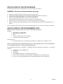
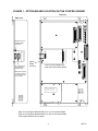
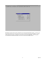
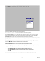
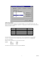
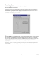
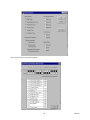
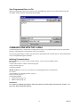
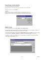
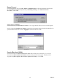
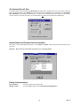
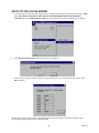
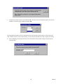
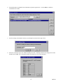
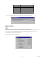
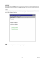
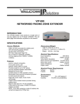
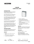
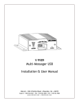
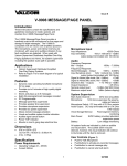
Issue 8 TALKBACK INTERCOM SYSTEM V-2926 OPTION BOARD The V-2926 Option Board is an add-on feature for the V-2924A Expandable Zone Talkback Intercom System. The addition of this board provides the following supplemental features: Time sync output Custom page groups Enhanced Caller ID Flexible Architectural numbering plan Interface to the PC Programming Tool Store user data to EEROM Real time clock for SMDR printer Auto detect for Com Port or Modem Auto adjust for Daylight Savings Time Evacuation tone to specified groups Time tones to specified groups Read software/firmware revision numbers Dimensions/Weight 5.3” L x 3.0” W x 1.1” D (13.5cm L x 7.6cm W x 2.8cm D) 0.9 lbs (0.4 kg) The V-2924A Programming Tool is a windows based software tool designed to interface with the V-2926 Option Board. The Option Board and the Programming Tool must both be installed to access the additional features provided by the Option Board. All features must be set with the Programming Tool when the Option Board and Programming Tool are installed. CONTENTS INSTALLATION OF THE OPTION BOARD INSTALLATION OF THE PROGRAMMING TOOL Figure 1 - Option Board Location on the Control Board USING THE PROGRAMMING TOOL System Configuration Architectural Number and CLID Programming Audio Connection Class of Service Custom Page Groups System Save Programmed Data to File COMMUNICATING WITH THE V-2924A Initiating Communications Direct Connect, Modem Connect Select Dialing Method Modem Connect, Manual Connect Send Data to V-2924A/Receive Data from V-2924A Set System Date and Time Read Software and Firmware Revision Number Ending Communications SETUP OF THE V-2924A MODEM MENU OPTIONS Print, Window, Help, Exit TECHNICAL ASSISTANCE, WARRANTY 1 2 2 3 4 4, 5 6, 7 7, 8 8 9 9,10 11 11 11 11, 12 12, 13 13 14 14 14 15-18 18, 19 20 947213 INSTALLATION OF THE OPTION BOARD The Option Board must first be installed on the Control Unit Board (See Figure 1). WARNING: Disconnect main power before servicing. Remove the side plate and top cover of the Control Unit and set aside. Slide small side plate upward to provide opening for Option Board connector (See Figure 1). Align J3 on the Option Board directly over J1 on the Control Board Align J4 on the Option Board directly over JP2 on the Control Board. Press Option Board firmly in place to make sure connectors are seated properly. Replace the top cover and side plate of the Control Unit and plug in the power supply. Plug PC Communication Cable (included) into P1, PC Programming Port (located on the Option Board - See Figure 1). The V-2926 Option Board requires the use of the PC Programming Tool to access the various features it provides. INSTALLATION OF THE PROGRAMMING TOOL Minimum Computer Requirements for the Valcom V-2924A Programming Tool: Hardware: 80486 (higher is recommended) Hard drive with 30 Mbytes free Mouse 8 Mbytes of RAM (more is recommended) 1 available serial communication port Operating System: The Programming Tool is 32-bit and requires Windows 95, Windows 98, or Windows NT 4.0. The Rev 2 Programming Tool is compatible with previous versions of hardware, however, the current hardware is not compatible with previous versions of the Programming Tool. The programming tool software is furnished on 1.4 MB disks and must be installed to the hard drive. To install the software: On the taskbar, click the Start button Insert disk 1 Select Run Type a:\Setup (Assuming a: is the disk drive being used) Follow on-screen instructions for full installation, changing disks as the prompt requests The Valcom V-2924A Programming Tool will automatically appear in the Programs list 2 947213 FIGURE 1 - OPTION BOARD LOCATION ON THE CONTROL BOARD Top View Side View RS232 Serial Port for SMDR (DB9 Connector) P10 P1 JP2 J1 PC Programming Port (located on Option Board) Option Board Location J3 and J4 are located on the under side of the Option Board. Slide plate covering connector ports up to provide opening for connector HIGH VOLTAGE AREA DISCONNECT POWER BEFORE SERVICING Align J3 on the Option Board directly over J1 on the Control Board Align J4 on the Option Board directly over JP2 on the Control Board Press Option Board firmly into place. 3 947213 USING THE PROGRAMMING TOOL On the taskbar, click the Start button, point to Programs, select Valcom V-2924A Programming Tool. The V-2924A Programming Tool splash screen appears momentarily and then the Programming screen comes into view V-2924A System Configuration To begin the programming process, click on File. A pull-down menu appears allowing selection of a previously programmed file (click on Open) or the ability to create a new file (click on New). The following instructions assume a New configuration file is being created. Click on New from the pull-down menu. A System Configuration screen is displayed to allow selection of the installed components within the system. Select one of the following from the list: For a 24 station system select Main Board. For a 48 station system select Main Board + Expansion 1. For a 72 station system select Main Board + Expansion 1, 2. For a 96 station system select Main Board + Expansion 1, 2, 3. Press OK to accept the present selection or Cancel to re-select. When selection is complete, the Programming Window Screen will be displayed. (To display the configuration of the system press the Details button). 4 947213 V-2924A When OK is selected from the System Configuration screen, the Programming Window appears - see below. The Programming Window allows each option to be accessed by selecting the option and pressing Open or by double clicking on the selected option. All functions can be listed at once by pressing Open All. (All of the options accessed through the Programming Window can also be accessed from the pulldown menus). 5 947213 V-2924A Architectural Number and CLID (Caller ID) Programming The first function to configure is the Architectural Number and CLID Programming. The Architectural Number is a 1 to 4 digit number that is dialed by the phone to connect to a specific speaker. Flexible architectural numbering is often selected to allow speakers and room numbers to match. The CLID Programming allows a name or up to 15 character description to be entered for each station. The information entered in the CLID description field will be displayed on the phone or Caller ID unit if provided as part of the system. The Edit Station Entry allows a CLID description to be entered for each station. Example: 105 would be the Arch # and MR. HALL would be the CLID description (15 character limit). The Delete Station Entry allows removal of selected architectural and CLID descriptions. Auto Numbering assigns the Arch # in sequential order. The beginning number is the currently selected station; an ending number must be specified. To Auto Number – Highlight station where architectural numbering begins. Select Edit Station Entry. Enter beginning architectural number and select OK. Select Auto Numbering and enter last architectural number (must be a higher number). Select OK. Enter information for the Main Board as well as each Expansion Unit being used and press OK to accept. 6 947213 Audio Connections This screen allows selection of groups to receive Background Music, Time Tones and Emergency Tones. This sample system consists of a “Main Board + Expansion 1” so eight groups are available to receive audio connections. (Each group contains six stations). Group 1 Group 2 Group 3 Group 4 Group 5 Group 6 Group 7 Group 8 Stations 1, 2, 3, 4, 5, 6 Stations 7, 8, 9, 10, 11, 12 Stations 13, 14, 15, 16, 17, 18 Stations 19, 20, 21, 22, 23, 24 Stations 25, 26, 27, 28, 29, 30 Stations 31, 32, 33, 34, 35, 36 Stations 37, 38, 39, 40, 41, 42 Stations 43, 44, 45, 46, 47, 48 Main Board Main Board Main Board Main Board Expansion 1 Expansion 1 Expansion 1 Expansion 1 Click on the tab of the desired feature to program zones. Click on each group button to receive the audio connection. If all groups are to receive an audio connection for the specific feature, select Include All. The zones for each feature: BGM, Time Tone and Emergency, are selected in the same manner. Defaults: BGM Time Tone Emergency - All Off - All On - All On After zones for each feature have been selected, press the OK button. 7 947213 The Audio Connections screen disappears, with the Programming Window still being active to allow selection of other options. Class of Service. Class of Service defines how a call originated by a button press will be queued for answer by the attendant. Emergency Only - Top priority. Stations programmed as Emergency Only are moved to the top of the priority list to be answered first. Normal/Emergency - Calls from stations programmed as Normal/Emergency are received in the queue as they are made. 1 button press from the station, the call is received as a normal call; 4 button presses from the station, the call is received as an emergency call. Normal Only - Calls from stations programmed as Normal Only are received in the queue as Normal priority whether 1 or 4 button presses are made at the calling station. Set the Class of Service for all Groups on the Main Board as well as any Expansion Boards. Press the down arrow at the end of the Class of Service field to display the available types of service for selection. When finished, press the Close button. Default option of all stations, with or without the Option Board installed, is Normal/Emergency. 8 947213 Custom Page Groups When Custom Page Groups is selected, the following screen is displayed. There are 4 Custom Page Groups available. Select the Page Groups to receive custom paging by clicking on the desired box. Each Custom Page Group can contain all groups or a combination of groups. (Example: Custom Page Group 50 could contain page groups 1, 2, and 3 and Custom Page Group 52 could contain page groups 1, 2, 7, and 8). Select OK after all desired page groups are defined. System Next select System from the Programming Window. A check in the box means ON (selected); an empty box means OFF (not selected). Select the desired options and click on OK to exit this screen. The options are described in more detail in the Control Unit (V-2924A) document or select Help from the pull-down menu for on-screen details. The Dip Switch button displays the dip switch equivalent (see next page) of the options selected with the programming tool. IMPORTANT: Options set using the programming tool override options selected manually using the Control Unit dip switches. 9 947213 Dip switch equivalent of programmed options. 10 947213 Save Programmed Data to a File When the programming selections are complete, click on the File menu option to access the pull-down menu and select Save. Define fine name and location and press Save. A COMMUNICATING WITH THE V-2924A Communicating with the V-2924A allows sending and receiving of user programmed data, Setting of System Date and Time, and reading the revision numbers of the system firmware. Once system programming is complete, this data must be downloaded to the V-2924A System. This communication can be accomplished through two methods: Initiating Communications Direct Connect (PC is on site with the V-2924A System - can be accessed via RS232 cable). To Connect: Connect cable from the V-2924A to the PC being used. Set up Com Port (page 12). Connection complete. Modem Connect (PC is off site or can only be accessed using phone lines to communicate). To Connect: Set up modem (User required procedure - page 12). Set up Com Port (page 12). Select Dialing Method Modem Connect (page 12) Manual Connect (page 13) REMINDER: For a modem to communicate with the V-2924A, there must be a remote modem connected to the V-2924A. See page 15 for Setup of the Remote Modem. 11 947213 Direct Connect - Set Up Com Port Select File, Com Setup, Com Port Selection. If the port is known, use the down arrow to locate the number, select it and press OK. If the port is not known, select Auto Find. Reminder: If direct connect is being used, make sure cables are connected and V-2924A is on. If modem connect is being used, make sure modem is installed and working properly. Modem Connect From the Programming Tool, select File, Modem, and then Modem Connect. The screen below appears. Enter the number to dial or select a phone number from the list displayed. Numbers can be added, edited, or deleted from the list. Up to 10 numbers can be stored. Once the desired phone number is displayed in the Number to Dial field, click on the Dial button. Messages should be displayed stating, "Initializing", "Dialing", and "Modem Connection Successful". Click on OK. If modem fails to connect, verify modem was set up properly during system installation. Refer to section titled, "Setup of the V-2924A Modem," page 15. 12 947213 Manual Connect From the Programming Tool, select File, Modem, and Manual Connect. Follow the instructions as described on the screen. Messages should be displayed stating, "Initializing","Dialing", and "Modem Connection Successful". Click on OK. Send data to V-2924A From the main menu, select Send Data to V-2924A. If a file is open, that file will be sent to the V-2924A System. If no file is open when Send Data to V-2924A is selected, the screen appears to allow selection of the data file to be opened and downloaded to the V-2924A. Highlight the desired file and click on OK. Receive Data from V-2924A From the main menu, select Receive Data from V-2924A. This will take place automatically. If you are not allowed to select Receive Data from V-2924A, close the currently open file and try again. Messages will be displayed stating Receiving Data, Receive Data Completed Successfully. Click on OK. 13 947213 Set System Date and Time Set System Date/Time by clicking on the Date/Time pull-down menu. Up/Down arrows are used to move date and time to the desired setting. Press Update to set the new Date/Time or Cancel to leave unchanged. The Automatic DST Adjustment can be enabled or disabled here. The DST correction is based on the pre-2007 rules (first Sunday of April, last Sun of October) therefore it is recommended to not enable the Automatic DST Adjustment. Read Software and Firmware Revision Numbers This feature is accessed through the Help menu. Select Help, then About. This option provides information for all processors. Reminder: The PC must be connected to the system to access this information. V-2924A V-2924A Ending Communications Direct Connect: Modem Connect: No action required, just unplug cable. From the pulldown menu, select File, Modem, Modem Release. 14 947213 SETUP OF THE V-2924A MODEM 1. To transfer data from a PC through a modem to the V-2924A System, the Remote Modem must be setup. THIS IS A "ONE-TIME" PROCEDURE THAT SHOULD BE PERFORMED WHEN THE MODEM IS INSTALLED. Select Communications Setup from the File Menu as shown in the following screen display: V-2924A A A 2. Select Remote Modem Setup and the following screen is displayed: 3. If Yes is selected, the dip switches at the back of the modem must be set to the positions shown below. Press OK to continue. The following screen is displayed after selecting No from the question of using a US Robotics modem, or after selecting Yes, setting the dip switches and pressing OK. 15 947213 4. Complete the instructions on the screen and click OK. The next screen to be displayed requests selection of a COM Port. Select the proper COM Port and click OK. The program then attempts to test the communication line between the PC and the modem. If the connection is okay, continue to Step 5. If the connection fails, you can Abort the setup, Retry the setup, or Ignore the warning. 5. After establishing a successful connection, restore the modem's factory default settings as shown below by clicking on Yes. 16 947213 6. The default modem commands for the US Robotics Sportster appear below. Click on Enter to send these commands to the modem. 7. Save the settings to the modem's memory by selecting Yes as shown in the figure below. 8. If Yes was selected in step 2, now with the modem power OFF, set the dip switches to the settings shown below and then click on OK. For a description of DIP switch functions, refer to the table below. 17 947213 Dip Switch Number SW1 SW2 SW3 SW4 SW5 SW6 SW7 SW8 9. Description Override DTR Verbal Result Codes Suppress Result Codes Echo Offline Commands Auto Answer on Ring Carrier Detect Normal Load NVRAM Defaults on Power-up Smart Mode After modem setup is complete, the screen below appears verifying a successful setup.. A. MENU OPTIONS PRINT The print option allows the system to provide a hard-copy verification of how the system is programmed. To print, the PC must be connected to a printer via the RS-232 serial printer port (DB9 connector). To access this option, select File and then Print. A screen (shown below) appears to allow selection of all programmed options or individual options for printing. This screen shows all items selected for printing. 18 947213 WINDOW The pull-down menu titled Window, allows several screens to be closed at once. Instead of going through several open screens, closing them individually, select Window, Close All or select the screens individually from the pulldown window. HELP The Help pull-down menu provides on-screen definition of elements provided by the V-2924A Talkback Intercom System. Select Help, select Contents. Click on General Description or Detailed Information to view the list of topics available through the Help menu. V-2924A A EXIT Select Exit from the File pull down to close the Programming Tool. 19 947213 TECHNICAL ASSISTANCE Assistance is available from the factory when problems are encountered. Call (540) 563-2000 and press 1 for Technical Support, or visit our website at http://www.valcom.com. Valcom equipment is not field repairable. Valcom, Inc. maintains service facilities in Roanoke, VA. Should repairs be necessary, attach a tag to the unit clearly stating company name, address, phone number, contact person, and the nature of the problem. Send the unit to: Valcom, Inc. Repair and Return Dept. 5614 Hollins Road Roanoke, VA 24019-5056 VALCOM LIMITED WARRANTY Valcom, Inc. warrants its products only to the original purchaser, for its own use, to be free from defects in materials and workmanship under conditions of normal use and service for a period of one year from the date of shipment. This Limited Warranty obligation shall be limited to the replacement, repair or refund of any such defective device within the warranty period, provided that: 1. inspection by Valcom, Inc. indicates the validity of the claim; 2. the defect is not the result of damage, misuse or negligence after the original shipment; 3. the product has not been altered in any way or repaired by others and that factory sealed units are unopened (a service charge plus parts and labor will be applied to units defaced or physically damaged); 4. freight charges for the return of products to Valcom are prepaid; 5. all units 'out of warranty' are subject to a service charge. The service charge will cover minor repairs (major repairs will be subject to additional charges for parts and labor). This Limited Warranty is in lieu of and excludes all other warranties, expressed or implied and in no event shall Valcom, Inc. be liable for any anticipated profits, consequential damages, loss of time or other losses incurred by the buyer in connection with the purchase, operation, maintenance, installation, removal or use of the product. The maximum liability of Valcom under this warranty is limited to the purchase price of the specific Product covered by the warranty. Disclaimer. Except for the Limited Warranty provided herein, the product is provided “as-is” without any warranty of any kind whatsoever including, without limitation, any WARRANTY OF MERCHANTABILITY, FITNESS FOR A PARTICULAR PURPOSE OR NON-INFRINGEMENT. This warranty specifically excludes damage incurred in shipment. In the event a product is received in damaged condition, the carrier should be notified immediately. Claims for such damage should be filed with the carrier involved in accordance with the F.O.B. point. Headquarters: Valcom, Inc. 5614 Hollins Road Roanoke, VA 24019-5056 Phone: (540) 563-2000 FAX: (540) 362-9800 20 947213