1
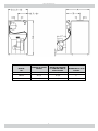
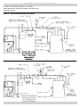
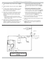
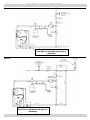
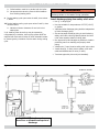
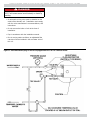
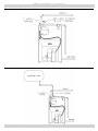
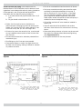
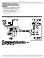
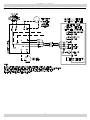
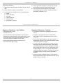
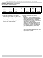
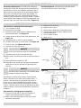
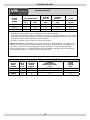
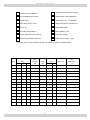
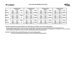
SW SERIES 2
OIL FIRED DIRECT EXHAUST
CAST IRON BOILER
Model
SW3065
SW4100
SW5125
INSTALLATION, OPERATION &
MAINTENANCE MANUAL
Tested For 75 psig
ASME Working Pressure
Manufactured by:
ECR International, Inc.
An ISO 9001-2008 Certified Company
2201 Dwyer Avenue, Utica NY 13501
web site: www.ecrinternational.com
P/N# 240009678, Rev. B [02/2013]
DIMENSIONS
A
LENGTH OF FLUSH
JACKET
B
FRONT OF CASTING
TO CENTER LINE OF
FLUE OUTLET
DIAMETER OF FLUE
OUTLET
SW3065
17 7/8"
11 1/4"
4"
SW4100
21 1/2"
12 5/8"
4"
SW5125
25 1/8"
14 1/4"
4"
BOILER
NO.
2
C
TABLE OF CONTENTS
Dimensions................................................................................................................................. 2
Safety Symbols .......................................................................................................................... 3
Installation ................................................................................................................................ 4
Connecting Supply And Return Piping ............................................................................................. 5
Recommended Piping For Boilers Equipped With A P3 Or T4 Tankless Heater........................................ 9
Options Utilizing 3/4" Tapping ......................................................................................................10
Oil Tank And Piping .....................................................................................................................11
Electrical Wiring .........................................................................................................................12
Sequence Of Operation................................................................................................................14
Operating Instructions.................................................................................................................15
Instructions To Obtain Proper Operation Of The Boiler-Burner Unit ....................................................16
Preventive Maintenance ...............................................................................................................17
Instructions For Opening And Closing Burner Swing Door .................................................................17
Ratings and Data ........................................................................................................................18
Service Check List ......................................................................................................................19
KEEP THIS MANUAL NEAR BOILER
RETAIN FOR FUTURE REFERENCE
IMPORTANT: Read the following instructions
COMPLETELY before installing.
Boiler installation shall be completed by qualified agency.
Safety Symbols & Warnings
The following defined symbols are used throughout this
manual to notify the reader of potential hazards of varying
risk levels.
Keep boiler area clear and free from combustible
materials, gasoline and other flammable vapors
and liquids.
DO NOT obstruct air openings to the boiler room.
Modification, substitution or elimination of factory
equipped, supplied or specified components may
result in personal injury or loss of life.
TO THE OWNER - Installation and service of this
boiler must be performed by a qualified installer.
TO THE INSTALLER - Leave all instructions with
boiler for future reference.
!
! WARNING
DANGER
Indicates a hazardous situation which, if not avoided,
WILL result in death or serious injury
! WARNING
Indicates a hazardous situation which, if not avoided,
could result in death or serious injury.
!
! WARNING
CAUTION
Fire, explosion, asphyxiation and electrical shock
hazard. Improper installation could result in death
or serious injury. Read this manual and understand
all requirements before beginning installation.
Indicates a hazardous situation which, if not avoided,
could result in minor or moderate injury.
NOTICE
NOTICE
Used to address practices not related to personal
injury.
When this product is installed in the Commonwealth
of Massachusetts installation must be performed by
a Licensed Plumber or Licensed Gas Fitter.
3
INSTALLATION
! WARNING
! WARNING
Improper installation, adjustment, alteration, service
or maintenance could result in death or serious
injury.
Fire hazard. Do not install boiler on combustible flooring
or carpeting. Failure to follow these instructions could
result in death or serious injury.
Installation
Installation shall conform to requirements of authority
having jurisdiction or in the absence of such requirements,
NFPA 31: Installation Code for Oil Burning Equipment.
FOR INSTALLATION ON NON-COMBUSTIBLE FLOORS ONLY
- The boiler must not be installed on carpeting or vinyl
flooring. Minimum clearances to combustible construction
are:
Minimum clearances to combustible construction are:
Where required by authority having jurisdiction, installation
shall conform to standard for Controls and Safety Devices
for Automatically fired boilers, ANSI/ASME CSD-1.
TOP .................................................0
FRONT .... ......................................24
FLUE CONNECTOR .............................2
REAR ...............................................6
LEFT SIDE ........................................0
RIGHT SIDE ......................................0
* "FOR ALCOVE INSTALLATION"
Locate boiler in front of final position before removing
crate. Provide level solid base as near to vent outlet
as possible and centrally located with respect to heat
distribution system as practical.
Allow 24 inches in front and top for servicing and cleaning,
or removing tankless water heating coil.
IN.
IN.*
IN.
IN.
IN.
IN.
Recommended clearance for service access should exceed
fire protection clearance.
When installed in utility room, door should be wide enough
to allow largest boiler part to enter, or permit replacement
of another appliance such as water heater.
TOP ............................................... 24
FRONT ........................................... 24
FLUE CONNECTOR .............................9
REAR ...............................................6
LEFT SIDE ...................................... 10
RIGHT SIDE ......................................6
IN.
IN.
IN.
IN.
IN.
IN.
Remove crate and plastic protective wrapper and inspect
for damage.
Our responsibility ceases upon delivery of the crated boiler
to the carrier in good condition. Any claims for damage or
shortage in shipment must be filed immediately against
carrier by consignee. Move boiler to permanent position by
sliding or walking.
4
CONNECTING SUPPLY AND RETURN PIPING
Circulators in following illustrations are mounted on
system supply side, mounting on system return side is also
acceptable practice.
Figure 1 - Typical Installation Using Circulators
Figure 2 - Typical Installation Using Zone Valves
5
CONNECTING SUPPLY AND RETURN PIPING
1. Typical installation using circulators shown in Figure
• Method used to protect systems using radiant
panels and material they are encased in from high
temperature supply water from boiler. See Figure
3.
1.
2. Typical installation using zone valves shown in Figure
2.
• Method used to protect boilers from condensate
forming due to low temperature return water.
Generally noticed in large converted gravity systems
or other large water volume systems. See Figure 4.
3. Hot water boilers installed above radiation level must
be provided with low water device either as part of
boiler or at time of boiler installation.
• Method used to protect boilers from condensate
forming as well as protecting heating system from
high water temperature. See Figure 5.
4. When boiler is connected to heating system utilizing
multiple zoned circulators, each circulator must be
supplied with flow control valve to prevent gravity
circulation.
• Reduced pressure back flow preventer must be
present under provisions required by Environmental
Protection Agency (EPA).
6. When using bypass piping, adjust valves A and B until
desired system temperature is obtained.
7. Bypass loop piping must be same size piping for supply
and return.
5. Bypass piping is an option which gives ability to adjust
8. Connect supply and return piping as suggested in
supply boiler water temperature to fit system or
condition of installation. This method of piping is not
typically required for baseboard heating systems.
Figure 6, when boiler is used in connection with
refrigerated systems:
Figure 3
Check local codes for maximum
from floor or allowable safe point of
discharge
6
CONNECTING SUPPLY AND RETURN PIPING
Figure 4
Check local codes for maximum
from floor or allowable safe point of
discharge
Figure 5
Check local codes for maximum
from floor or allowable safe point of
discharge
7
CONNECTING SUPPLY AND RETURN PIPING
A. Chilled medium must be in parallel with the boiler.
! WARNING
B. Use appropriate valves to prevent chilled medium
from entering heating boiler.
Burn and scald hazard. Safety relief valve could
discharge steam or hot water during operation.
9. During heating cycle open valves A and B, close valves
Install discharge piping from safety relief valve.
C and D.
• Use ¾” or larger pipe.
10. During heating cooling cycle open valves C and D, close
• Use pipe suitable for temperatures of 375°F (191°C)
or greater.
valves A and B.
A. Maintain minimum clearance of one inch to hot
water pipes.
• Individual boiler discharge piping shall be independent
of other discharge piping.
In air handling units where they may be exposed to
refrigerated air circulation, boiler piping system MUST be
supplied with flow control valves or other automatic means
to prevent gravity circulation of boiler water during cooling
cycle.
• Size and arrange discharge piping to avoid reducing
safety relief valve relieving capacity below minimum
relief valve capacity stated on rating plate.
• Run pipe as short and straight as possible to location
protecting user from scalding and properly drain
piping.
• Install union, if used, close to safety relief valve outlet.
• Install elbow(s), if used, close to safety relief valve
outlet and downstream of union (if used).
• Terminate pipe with plain end (not threaded).
Figure 6
Check local codes for maximum
from floor or allowable safe point of
discharge
8
RECOMMENDED PIPING FOR BOILERS EQUIPPED WITH A P3 OR T4 TANKLESS HEATER
!
DANGER
Burn, scald hazard. Water temperatures exceeding
125º F will cause severe burns instantly or death by
scalding.
• An automatic mixing valve must be installed on the
outlet of the domestic coil. Installation must comply
with the valve manufacture’s recommendations, and
instructions.
• Do not remove the bolts or limit at the time of
installation.
• Pipe in accordance with the installation manual.
• Due to varying water conditions, an adjustable flow
restrictor must be installed in the cold water inlet of
this coil.
Figure 7 Recommended Piping For Boilers Equipped With A P3 Or T4 Tankless Heater
9
OPTIONS UTILIZING 3/4" TAPPING
Figure 8 - Optional Location For Air Vent
Figure 9 - Optional Location For Expansion Tank (Non-Diaphragm Type)
10
OIL TANK AND PIPING
Install Oil tank and piping in accordance with the
National Board of Fire Underwriters and in absence of such
regulations in accordance with authority having jurisdiction.
Oil storage tank, vent, fill pipe and caps should be in
accordance with the authority having jurisdiction.
A. In no case should vent pipe be smaller than 1-1/4"
I.P.S.
B. Fill pipe should not be less than 2" I.P.S.
• Do not run overhead fuel lines from tank to oil burner.
• Fuel pump connections and by-pass should be made
according to instructions attached to fuel pump. If
tank is more than 20' from the boiler, a two stage
fuel unit should be installed in place of single stage
pump supplied as standard equipment with burner.
Make certain rotation and speed are same and pump is
suitable for burner horsepower rating.
• Oil line filter and shut-off valve should be installed in
suction line.
• Suction line from tank to burner should be one
continuous piece of tubing to prevent air entering line.
Suction line, must be 3/8" O.D. copper tubing for runs
of 50 feet or less, and 1/2" O.D. for longer runs.
• Shut-off valves should be installed in both suction
and return lines at burner for convenience in servicing
burner.
• Oil return line, same size as suction line, must be used
on any installation where bottom of tank is below fuel
unit of burner.
• Allow extra tubing at burner so burner may be removed
from boiler for cleaning without disconnecting tubing.
(See Figures 10 & 11).
• Oil lines should be buried or otherwise protected from
mechanical injury.
• A UL approved flexible oil line may be used.
• Flare fittings on all oil lines are recommended.
• Compression fittings on suction line often allow air to
be drawn into fuel pump, making it difficult to maintain
oil pressure at nozzle.
Figure 10 - Typical Installation Single Pipe Oil
System
Figure 11 - Typical Installation Two Pipe Oil
System
11
ELECTRICAL WIRING
Install electrical wiring in accordance with
requirements of authority having jurisdiction, or
in the absence of such requirements, NFPA 70:
Electrical Code.
• Separate electrical circuit should be run from entry
box with fused disconnect switch in this circuit.
• See wiring diagrams in Figures 12 & 13 for
suggested circuitry and field wiring see Normal
Sequence of Operation in this manual.
• Wiring for zone valve installations are furnished with
zone valve packages.
Figure 12 - Wiring Diagram For Oil Fired Boilers Less Tankless Heater And Beckett Burner
12
ELECTRICAL WIRING
Figure 13 - Wiring Diagram For Oil Fired Boilers With Tankless Heater And Beckett Burner
13
ELECTRICAL WIRING
Thermostat Installation
1. Install thermostat on inside wall about four feet above
floor.
2. Never install thermostat on outside wall.
3. Do not install thermostat where it will be affected by:
A.
B.
C.
D.
E.
F.
4. Check thermostat operation by raising and lowering
thermostat as required to start and stop burner.
5. Instructions for final adjustment of thermostat
are packaged with thermostat (adjusting heating
anticipator, calibration, ect.).
Drafts
Hot or cold pipes
Sun light
Lighting fixtures
Television sets
A fireplace or chimney
SEQUENCE OF OPERATION
Sequence of Operation - Non-Tankless
Sequence of Operation - Tankless
• Thermostat calls for heat.
• Thermostat will activate, completing circuit to limit
control.
• Circulator turns on.
• Circulator motor starts and power is switched to
limit. If limit circuit is closed burner motor circuit is
energized.
• Limit checks boiler water temperature. Burner ignition
delayed until limit determines call for heat cannot be met
by residual heat in boiler and heat distribution system.
See limit literature for additional information.
• Burner motor starts prepurge and approximately 15
seconds after solenoid valve opens and ignition system
is activated, ignition will begin.
• Burner and circulator operation continues until
thermostat stops call for heat.
• In event boiler water temperature exceeds high limit
setting on boiler mounted limit control; Power will be
interrupted between limit control and ignition system.
Burner motor will continue to run in post purge mode
for approximately 2 min. or until water temperature
drops below high limit setting. Circulator will continue
to operate under this condition until thermostat is
satisfied.
• When thermostat is satisfied power is interrupted to
boiler mounted limit control and burner will run in post
purge mode for 2 minutes.
14
OPERATING INSTRUCTIONS
Venting system should be inspected at start of each heating
season.
• Check vent pipe from boiler to termination cap for
signs of deterioration by rust or cracked silicone joints.
Repair if necessary.
• Lever of safety relief valve, shown in Figure 17, on
page 18, on boiler should be operated periodically to
make sure it is functioning properly. Pressure relief
valve should open before water pressure exceeds
30 psi. reading on gauge. If pressure is exceeded
and pressure relief valve leaks water when boiler is
operating at normal pressures, immediately replace.
Corrosion can build up rapidly at valve seat preventing
it functioning as safety device.
Start-up and adjustment of oil burner (See oil burner
instructions for nozzle and electrode setting).
A. Check oil burner nozzle to make certain it is tight in
adapter. Burner mounting bolts should be tight.
B. Check electrode setting, as they may have been
jarred out of position during transportation.
C. Lubricate burner motor and circulator motor if
required. Some circulators are water lubricated and
do not require oiling.
D. Set room thermostat to call for heat.
E. Open all oil line valves.
F. Turn service switch on. Burner should start.
G. On one pipe fuel systems only, vent pump as soon
as burner starts. Allow oil to run until all traces of
air in the suction line disappear.
H. Turn “OFF” burner and install pressure gauge in
port on pump.
I. Start burner again and check oil pressure for 140
psi. Adjust if necessary.
Instruments are only reliable method to determine proper
air adjustments. Improperly adjusted burner causes soot
and high fuel bills because of incomplete combustion of fuel
oil. This in turn may require excessive boiler maintenance,
service costs. Consult competent service mechanic to make
proper adjustments with smoke tester, CO2 indicator and
draft gauge. Bacharach or Dwyer test kits include these
instruments.
• 1/4" diameter slot is provided in inspection cover plate
to take draft reading in combustion chamber.
• 3/8" hole is provided in vent appliance adapter to take
draft, CO2, smoke, and temperature readings.
• Adjust air dial on oil burner to obtain trace of smoke.
Measure CO2 at this point and increase air setting until
CO2 = 1-1.5% lower than reading at trace point.
• Check draft over fire and in vent, normal readings will
be positive (+.01 Over-fire & +.02 In Vent) W.C.
Table page 17 is provided as guideline for initial startup. Final adjustments MUST be made using combustion
instruments as previously mentioned.
15
INSTRUCTIONS TO OBTAIN PROPER OPERATION OF THE BOILER-BURNER UNIT
Check Safety Control Circuit after burner adjustments
have been made for satisfactory performance.
BECKETT SETTINGS
Boiler
No.
Burner
No.
Air
Damp
Pin
Pump
Pressure
Head
Nozzle
Furnished
SW3065
AFII 100
3.25
3
140 PSI
HLX 6
.60 45B
SW4100
AFII 100
7.50
5
140 PSI
HLX 6
.85 45B
SW5125
AFII 150
5.00
8
140 PSI
HLX 6
1.10 45B
A. HIGH LIMIT CONTROL: remove cover and note
temperature setting. See figure 15 on page 15. With
burner operating, decrease this setting to minimum
point. When boiler water temperature exceeds this
set point, high limit switch will open, shutting off
power to oil burner and starting post purge cycle for
approximately 2 minutes. Return setting to desired
high limit point. Burner should restart.
B. PRIMARY CONTROL AND FLAME SENSOR:
To Check:
• Flame failure - simulate by shutting off oil supply
with hand valve while burner is on. 15 seconds after
flameout, safety switch locks out, ignition stops,
motor stops and oil valve closes. To restart, open oil
supply valve and reset safety switch.
• Ignition failure - with burner off, unplug electrical
disconnect on burner harness. Disconnect one wire
from transformer and put wire nut on disconnected
wires . Restore power and run through start-up
procedure, safety switch should lockout as flame
failure. Reconnect wires after this procedure is
complete.
• Power failure - Turn off main power supply switch
while burner is operating. When burner stops, restore
power and burner should start.
If operation is not as described as above, check wiring and
controls.
16
PREVENTIVE MAINTENANCE
Preventive Maintenance of oil fired boiler reduces operating costs. Boiler and vent pipe should be inspected for
accumulation of soot or scale deposits periodically but at
least once every year before start of each heating season.
When soot is present on section walls and flueways, improper combustion will result, causing additional sooting
and scaling until flueways are completely closed. To remove
soot and scale from flueways, remove top jacket panel, top
clean-out plate, and open burner swing door. (Figure 14).
Periodic Inspection and tightening of tankless heater/
cover plate bolts will reduce risk of leaks.
INSTRUCTIONS FOR OPENING AND CLOSING BURNER SWING DOOR
Instructions for Opening Burner Swing Door
1. Turn off power to boiler.
2. Allow boiler to cool down.
3. Disconnect power cable at factory supplied burner
electrical disconnect. See Figure 15.
4. Loosen screws on sides of lower front jacket panel. See
Figure 15.
5. Pull bottom part of lower front panel forward.
6. Lift lower front panel up and off boiler. See Figure 15.
7. Close oil valve. See Figures 10 and 11.
8. Disconnect oil line from burner.
3.
4.
5.
6.
Replace oil line to burner.
Replace inlet air pipe.
Replace lower jacket panel, and tighten screws.
Connect power cable at factory supplied burner
electrical disconnect.
7. Turn on power to boiler.
8. Bleed oil line.
Figure 14
NOTICE
Do not try to swing door with oil line attached
9. Disconnect inlet air pipe from side of burner.
10. Remove nut from swing door stud on right hand side of
door.
11. Swing open burner and door to left.
12. Using flue brush, brush soot and scale into combustion
space where it can be removed through swing door
opening.
NOTICE
Use caution when vacuuming in the chamber area.
Damage to chamber could result.
Figure 15
Recommend to replace nozzle at start of each heating
season. Lubricate burner motor and circulator motor - if
required - with few drops of good grade light motor oil.
Do not over oil. Have competent service person service
burner, check controls and check electrodes for carbon or
cracks in insulators. Burners should be adjusted to produce
conditions shown in Start-up and Adjustment of Oil Burner
procedure.
Instructions for Closing Burner Swing Door
1. Swing burner and door to right until insulation is
slightly compressed and stud is exposed.
2. Attach nut to stud and tighten it until built in stop
contacts mounting door.
17
RATINGS AND DATA
RATINGS AND DATA
BOILER
MODEL
NUMBER
OIL BURNER INPUT(1)
HEATING
CAPACITY
AHRI NET
RATINGS (2)
A.F.U.E.
G.P.H.
MBH
MBH*
WATER
MBH
RATING
SW3065
.65
91
78
68
85.0
SW4100
1.00
140
120
104
85.0
SW5125
1.25
175
150
130
85.0
NOTES:
1. AHRI burner input is based on an oil heating value of 140,000 Btu/gal.
2. Net AHRI Water Ratings shown are based on a piping and pickup allowance of 1.15. Consult
manufacturer before selecting boiler for installations having unusual piping and pickup requirements,
such as intermittent system operation, extensive piping.
3. 120 Volts, 15 Amps, & 60 Hz. required to operate this boiler.
STANDARD EQUIPMENT: Crated Boiler, Flush Jacket, Oil Burner, Target Wall/Liner, Circulator-1 1/4",
Safety Relief Valve, Temperature Pressure Gauge, Drain Valve, Wiring Harness, Burner Electrical
Disconnect, Plastic Cover, Supply Tapping 2", Return Tapping 1¼", High Limit and Circulator
Control, Primary Control. For Tankless Heater Units-add Tankless Hot Water Coil, Flow Restrictor
and Combination High Limit, Low Limit, and Circulator Control.
TANKLESS WATER HEATER CAPACITIES
BOILER
MODEL
NUMBER
INPUT
RATE
G.P.H.
TANKLESS
HEATER
NUMBER
TANKLESS
HEATER CAPACITY
INTERMITTENT DRAW
G.P.M.
BOILER
WATER
CONTENT
GALS.
SW3065
.65
P3
CAPACITY AVAILABLE ON REQUEST
10.5
SW4100
1.00
T4
3.25
13.5
SW5125
1.25
T4
3.75
16.5
18
SERVICE CHECK LIST
Pump Pressure/Vacuum
Inspect Chimney and Flue pipe
Line Voltage/Motor Amps
Inspect and Clean Appliance
Smoke Test
Inspect Oil Line - Size/Leaks
Draft Over-fire/In Flue
Inspect Electrical Connections
CO2 or O2
Install New Filter
Flue Gas Temperature
Room Make-up Air
Proper Light-Off (Hot & Cold)
Electrode setting
Controls and Safety Devices
Nozzle-Size, Angle, Type
Measure with Instruments and Record results on chart provided below.
Date
Nozzle
Size
Angle
Type
Pump
Pressure
Smoke
PSI
NO.
19
Draft
O.F.
INF
CO2 or O2
Flue
Temperature
o
F
SW
OIL FIRED DIRECT EXHAUST
CAST IRON BOILER