1
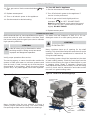
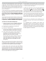
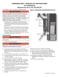
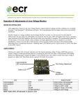
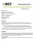
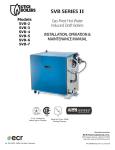
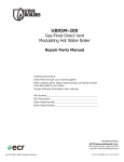
USER'S
INFORMATION
MANUAL
SERIES MGB
GAS FIRED HOT WATER HEATING BOILER
WARNING: If the information in this manual is not
followed exactly, a fire or explosion may result causing
property damage, personal injury or loss of life.
Do not store or use gasoline or other flammable
vapors and liquids in the vicinity of this or any
other appliance.
WHAT TO DO IF YOU SMELL GAS
• Do not try to light any appliance.
• Do not touch any electrical switch; do not use
any phone in your building.
• Immediately call your gas supplier from a
neighbor's phone. Follow the gas supplier's
instructions.
• If you cannot reach your gas supplier, call the
fire department.
Installation and service must be performed by a
qualified installer, service agency or the gas
supplier.
Do not use this boiler if any part has been under water. Immediately call a qualified service technician to
inspect the boiler and to replace any part of the control system and any gas control which has been under
water.
Should overheating occur or the gas supply fail to shut off, do not turn off or disconnect the electrical supply to
the pump. Instead, shut off the gas supply at a location external to the appliance.
Information and specifications outlined in this manual in effect at the
time of printing of this manual. ECR International reserves the right to
discontinue, change specifications or system design at any time without
notice and without incurring any obligation, whatsoever.
Check our website frequently for updates: www.ecrinternational.com
Utica Boilers
2201 Dwyer Ave.
Utica, NY 13501
P/N 37611701, Rev. B [8/2011]
USERS INFORMATION MANUAL
INSTRUCTIONS FOR OPERATION AND MAINTENANCE
OF GAS FIRED HOT WATER HEATING BOILER
RETAIN FOR FUTURE REFERENCE
SAFETY SYMBOLS & WARNINGS
Utica Boilers recommends all boiler maintenance be
performed by a trained heating technician.
The following defined symbols are used throughout
this manual to notify the reader of potential hazards of
varying risk levels.
Before any procedures are attempted on this appliance,
it is necessary to determine if the ignition system is a
electric or standing pilot system. If you are uncertain,
contact the manufacturer before proceeding.
DANGER
DANGER
!
Indicates a hazardous situation which, if
not avoided, WILL result in death or serious
injury.
CAUTION
!
Indicates a hazardous situation which, if not
avoided, may result in minor or moderate
injury.
WARNING
!
Indicates a hazardous situation which, if
not avoided, could result in death or serious
injury.
NOTICE
Indicates information which should be
followed to ensure proper installation and
operation.
2
LIGHTING INSTRUCTIONS
4.This appliance is equipped with an ignition device
which automatically lights the pilot. Do not try to
light the pilot by hand.
WARNING
!
Before lighting any type of pilot burner
(standing or intermittent), make certain the
hot water boiler and system are full of water
to minimum pressure of 12 lbs. per square
inch in the system, and also make certain
that the system is vented of air. Refer to the
following appropriate lighting instruction.
5.Turn gas control knob clockwise
See Figure 1.
6.Wait (5) minutes to clear out any gas. If you then
smell gas, STOP! Follow “What To Do If You Smell
Gas” on front cover of this manual. If you don’t smell
gas, go on to the next step.
LIGHTING PROCEDURE FOR BOILER WITH
INTERMITTENT PILOT SYSTEM
7.Turn gas control knob counterclockwise
“ON.”
to
8.Turn on all electric power to the appliance.
WARNING
!
to “OFF.”
If you do not follow these instructions exactly,
a fire or explosion may result causing property
damage, personal injury or loss of life.
9.Set thermostat to desired setting.
10. If the appliance will not operate, follow the instructions
“To Turn Off Gas To Appliance” on page 5 and call a
qualified service technician or your gas supplier.
A. This appliance is equipped with an ignition device which
automatically lights the pilot. Do not try to light the
appliance by hand.
B. Before operating, smell all around the appliance area
for gas. Be sure to smell next to the floor because
some gas is heavier than air and will settle on the floor.
Read "What To Do If You Smell Gas" on front page of
this manual.
Figure 1 - Intermittent Pilot
C. Use only your hand to push in or turn the gas control
knob. Never use tools. If the knob will not push in
or turn by hand, don’t try to repair it, call a qualified
service technician. Force or attempted repair may
result in a fire or explosion.
D. Do not use this appliance if any part has been under
water. Immediately call a qualified service technician
to inspect the appliance and to replace any part of the
control system and any gas control which has been
under water.
E.
F.
Operating Instructions For Intermittent Pilot
System
1. STOP! Read the safety information above.
2. Set the thermostat to lowest setting.
3. Turn off all electric power to the appliance.
3
LIGHTING INSTRUCTIONS
Lighting Procedure For Boiler With
Continuous Pilot System
Figure 2 - Gas Control Knob
For your safety read before Lighting.
WARNING
!
If you do not follow these instructions exactly,
a fire or explosion may result causing property
damage, personal injury or loss of life.
A. This appliance has a pilot which must be lighted by
hand. When lighting the pilot, follow these instructions
exactly.
B. Before lighting, smell all around the appliance area for
gas. Be sure to smell next to the floor because some
gas is heavier than air and will settle on the floor. Read
"What To Do If You Smell Gas" on front page of this
manual.
T
LE
IN
Figure 3 - Continuous Pilot Gas Valve
C. Use only your hand to push in or turn gas control knob
or reset button. Never use tools. If the knob or reset
button will not push in or turn by hand, don’t try to
repair it, call a qualified service technician. Force or
attempted repair may result in a fire or explosion.
D. Do not use this appliance if any part has been under
water. Immediately call a qualified service technician
to inspect the appliance and to replace any part of the
control system and any gas control which has been
under water.
E.
F.
Lighting Instructions For Continuous Pilot
1. STOP! Read the safety information above.
2. Set the thermostat to lowest setting.
3. Turn off all electric power to the appliance.
8. Turn gas control knob counterclockwise
"PILOT."
4. Remove access panel and burner door.
5. Turn gas control knob clockwise
Figures 2 and 3.
to
9. Push in gas control knob or reset button if so equipped,
all the way in and hold. Immediately light the pilot
with a match. Continue to hold the gas control knob
or reset button in for about 1 minute after the pilot
is lit. Release knob or button, and it will pop up back
up. Pilot should remain lit. If it goes out, repeat
steps 5 through 9.
to "OFF." See
Note Some gas control knobs cannot be turned from
"PILOT" to "OFF" unless knob is pushed in slightly.
DO NOT FORCE.
6. Wait (5) minutes to clear out any gas. If you then
smell gas, STOP! Follow "What To Do If You Smell
Gas" on front page of this manual. If you don't smell
gas, go to the next step.
* If knob or button does not pop up when released,
stop and immediately call a qualified service
technician or your gas supplier.
* If the pilot will not stay lit after several tries, turn
the gas control knob clockwise
to "OFF"
and call a qualified service technician or your gas
supplier.
7. Find pilot. Follow metal tube from gas control.
Depending on the model of the boiler, pilot is either
mounted on the base or on one of the burner
tubes.
4
10. Replace burner door.
LIGHTING INSTRUCTIONS
11. Turn gas control knob counterclockwise
"ON."
To Turn Off Gas To Appliance
1. Set the thermostat to lowest setting.
to
12. Replace access panel.
2. Turn off all electric power to the appliance if
service is to be performed.
13. Turn on all electric power to the appliance.
3. Push in gas control knob slightly and turn
14. Set thermostat to desired setting.
to "OFF." DO NOT FORCE.
clockwise
Note Some gas control knobs cannot be turned
from "PILOT" to "OFF" unless knob is pushed in
slightly. DO NOT FORCE.
4. Replace access panel.
GENERAL INSTRUCTIONS
Before seasonal start-up, have a qualified service agency
check the boiler for soot and scale in the flues, clean
the burners and check the gas input rate to maintain
high operating efficiency.
Put about one half teaspoon of SAE 20 or 30 nondetergent motor oil in each opening twice a year.
CAUTION
!
Do Not Over Oil!!
CAUTION
!
Label all wires prior to disconnection when
servicing controls. Wiring errors can cause
improper and dangerous operation.
Many circulators have an oil opening for the shaft
bearing. This should be oiled at the same time for quiet
operation. Follow the manufacturer's instructions for
oiling the shaft bearing.
Verify proper operation after service.
The venting system should be inspected at the start
of each heating season. Check the vent pipe from the
boiler to the chimney for signs of deterioration by rust
or sagging joints. Repair if necessary. Remove the
vent pipe at the base of the chimney or flue and using
a mirror, check vent for obstruction and make certain
the vent is in good working order.
The service agency or owner should make certain the
system is filled with water to minimum pressure and
open air vents, if used, to expel any air that may have
accumulated in the system. Check the entire piping
system and, if any leaks appear, have them repaired.
Figure 5 - Boiler Flue Gas Passageways
Figure 4 - Circulator
Intergral Draft
Hood
Blocked Vent
Safety Switch
Burner
Door
Burners
Rollout Switch
4 Section Boiler
Many circulators like the one pictured in Figure 4
(above) require periodic servicing. The motor usually
has openings at each end to lubricate the bearings.
Orifices
5
Base
Jacket Base
Panel
Rollout Switch
2,3,5,6,7
Section Boiler
GENERAL INSTRUCTIONS
The boiler flue gas passageways may be inspected by
a light and mirror. Remove the burner door. Place a
trouble lamp in the flue collector through the draft relief
opening. With the mirror positioned above the burners,
the flue gas passageways can be checked for soot or
scale. See Figure 4.
The pilot flame should envelop 3/8 to 1/2 inch of the
tip of the pilot thermocouple, ignition/sensing electrode
or mercury sensor. See Figure 7
To adjust the pilot flame, remove the pilot adjustment
cover screw and turn the inner adjustment screw
to increase or clockwise
counterclockwise
to decrease pilot flame. Be sure to replace cover screw
after adjustment to prevent possible gas leakage.
In the event the flow of combustion products through
the boiler venting system becomes blocked, the blocked
vent safety switch will shut the main burner gas off. If
this condition occurs, do not attempt to place the
boiler in operation. Contact a qualified service
agency.
The burners and pilot should be checked for signs of corrosion, rust or scale build-up. The area around the boiler
must be kept clear and free of combustible materials,
gasoline and other flammable vapors and liquids.
If the boiler flue-ways become blocked, a flame rollout
safety switch will shut the main burner gas off. If this
condition occurs, do not attempt to place the boiler
in operation. Contact a qualified service agency.
The free flow of combustion and ventilating air to
the boiler and boiler room must not be restricted or
blocked.
To Clean The Flue Gas Passageways
It is suggested that a qualified service agency be
employed to make an annual inspection of the boiler
and heating system. They are experienced in making the
inspections outlined above and, in the event repairs or
corrections are necessary, can make the proper changes
for safe operation of the boiler.
1. Remove the burners from the combustion chamber by
raising the burners up from the manifold orifices and
pulling toward the front of the boiler. See Figure 5.
2. Disconnect the vent pipe from the draft hood.
3. Remove the top jacket panel.
4. Remove the combination flue collector and draft hood
from the boiler castings by loosening the nuts on the
hold down bolts located on each side of the collector.
5. Place a sheet of heavy paper or similar material over
the bottom of the base and brush down the flue
passageways. The soot and scale will collect on the
paper and is easily removed with the paper.
With the paper still in place in the base, clean the top
of the boiler castings of the boiler putty or silicone
used to seal between the castings and flue collector.
Make certain that chips are not lodged in the flue
passageways.
When the cleaning process is complete, restore the boiler
components to their original position. Use boiler putty
or IS-808 GE silicone (available from the distributor) to
seal around the flue collector and boiler castings.
A visual check of the main burner and pilot flames
should be made at the start of the heating season and
again mid-season. The main burner flame should have a
well defined inner blue mantel with a lighter blue outer
mantel. Check the burner throats and burner orifices
for lint or dust obstruction. See Figure 6.
6
GENERAL INSTRUCTIONS
Figure 6 - Burner Flame
Figure 7 - Burner Pilot Flame
Figure 8 - Burners, Burner Orifices
7
NOTES
Utica Boilers
2201 Dwyer Ave.
Utica, NY 13501
Date of Installation:
Boiler Model #:
Installed By:
An ISO 9001-2008 Certified Company
ECR International, Inc.
2201 Dwyer Ave.
Utica, NY 13501
8