1
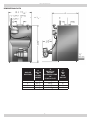
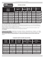
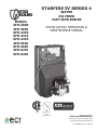
STARFIRE IV SERIES 4
WATER
OIL FIRED
CAST IRON BOILER
Models
SFH-3085
SFH-3100
SFH-4100
SFH-4125
SFH-4145
SFH-5160
SFH-5185
SFH-6175
SFH-6210
INSTALLATION, OPERATION &
MAINTENANCE MANUAL
Tested For 75 psi
ASME
Working Pressure
Manufactured by:
ECR International, Inc.
2201 Dwyer Avenue, Utica NY 13501
web site: www.ecrinternational.com
An ISO 9001-2008 Certified Company
P/N 240009735, Rev. F [12/2014]
TABLE OF CONTENTS
Dimensions������������������������������������������������������������������������������������������������������������������� 3
Boiler Ratings & Capacities������������������������������������������������������������������������������������������� 4
Introduction������������������������������������������������������������������������������������������������������������������ 5
Ventilation & Combustion Air���������������������������������������������������������������������������������������� 6
Connecting Supply And Return Piping��������������������������������������������������������������������������� 9
System Piping������������������������������������������������������������������������������������������������������������� 13
Venting System Inspection & Installation.....................................................................16
Oil Tank And Piping����������������������������������������������������������������������������������������������������� 17
Electrical Wiring���������������������������������������������������������������������������������������������������������� 18
Operating Instructions������������������������������������������������������������������������������������������������ 23
Keep this manual near boiler and
Retain for future reference
! WARNING
Boiler installation shall be completed by qualified agency.
All boiler and venting installations shall be done
by qualified agency and in accordance with
appropriate Manufacturer’s Installation, Operation
and Maintenance Manual. Installing or venting boiler
or any other appliance with improper methods or
materials could result in serious injury or death due
to fire or to asphyxiation from poisonous gases such
as carbon monoxide which is odorless and invisible.
Become familiar with symbols identifying potential
hazards.
This is the safety alert symbol. Symbol alerts you to
potential personal injury hazards. Obey all safety messages
following this symbol to avoid possible injury or death.
!
DANGER
! WARNING
Indicates a hazardous situation which, if not
avoided, WILL result in death or serious injury
Modification, substitution or elimination of factory
equipped, supplied or specified components could
result in death or serious injury.
! WARNING
Indicates a hazardous situation which, if not avoided,
could result in death or serious injury.
Keep boiler area clear and free from combustible
materials, gasoline and other flammable vapors and
liquids.
DO NOT obstruct air openings to boiler room.
To the owner: Installation and service of this boiler must
be performed by qualified installer.
To the installer: Leave all instructions with boiler for
future reference.
Installation in Commonwealth of Massachusetts must be
performed by Licensed Plumber or Licensed Gas Fitter.
! CAUTION
Indicates a hazardous situation which, if not avoided,
could result in minor or moderate injury.
NOTICE
Used to address practices not related to personal
injury.
2
DIMENSIONS
DIMENSIONAL DATA
BOILER
SECTION
A
DEPTH
OF
FLUSH
JACKET
B
FRONT OF
CASING
TO CENTER LINE
OF
FLUE OUTLET
C
DIA.
OF
FLUE
OUTLET
3
17 ⅞"
11 ¼"
6"
4
21 ½"
12 ⅝"
6"
5
25 ⅛"
14 ¼"
7"
6
29¼
15 ¹⁵/16”
8”
3
BOILER RATINGS & CAPACITIES
BOILER RATINGS
BOILER
MODEL
NUMBER
(2)
(1)
(3)
OIL BURNER
INPUT
HEATING
CAPACITY
NET
RATINGS
WATER
gph
*Mbh
*Mbh
*Mbh
(3)
A.F.U.E.
CHIMNEY
SFH-3085W
SFH-3085WT
0.85
119
103
90
85.0%
8X8X15
SFH-3100W
SFH-3100WT
1.00
140
119
103
84.0%
8X8X15
SFH-4100W
SFH-4100WT
1.00
140
122
106
86.0%
8X8X15
SFH-4125W
SFH-4125WT
1.25
175
151
131
85.0%
8X8X15
SFH-4145W
SFH-4145WT
1.45
203
173
150
84.0%
8X8X15
SFH-5160W
SFH-5160WT
1.60
224
193
168
85.0%
8X8X15
SFH-5185W
SFH-5185WT
1.85
259
221
192
84.0%
8X8X15
SFH-6175W
SFH-6175WT
1.75
245
212
184
85.0%
8X8X15
SFH-6210W
SFH-6210WT
2.10
294
252
219
84.0%
8X8X15
*Mbh = 1,000 Btu per hour [Btu = British Thermal Unit]
1
Oil burner input based on 140,000 Btu per gallon.
2
Net AHRI water ratings shown are based on a piping and pickup allowance of 1.15. Consult manufacturer
before selecting a boiler for installation having unusual piping and pickup requirements, such as intermittent
system operation, extensive piping systems, etc.
3
Heating Capacity and AFUE based on 13.0% CO2 with -0.02” W. C. draft over fire and #1 smoke or less.
Tested in accordance with U.S. Department of Energy test procedures.
T= Tankless
STANDARD EQUIPMENT: Crated Boiler, Flush Jacket, Oil Burner, Target Wall/Liner, Circulator- 1¼”, Safety
Relief Valve, Temperature Pressure Gauge, Drain Valve, Wiring Harness, Burner Electrical Disconnect, Plastic
Cover, Supply Tapping-2”, Return Tapping-1 1/2”, High Limit and Circulator Control, Primary Control. For
Tankless Heater Units add Tankless Hot Water Coil and Triple Combination High Limit/Low Limit/Circulator
Control.
TANKLESS WATER HEATER CAPACITIES
BOILER
MODEL
NUMBER
INPUT
RATE
G.P.H.
TANKLESS
HEATER
NUMBER
TANKLESS
HEATER CAPACITY
INTERMITTENT DRAW
G.P.M.
BOILER
WATER CONTENT
GALS.
SFH-3085WT
0.85
T3
3
10.5
SFH-3100WT
1.00
T3
3¼
10.5
SFH-4100WT
1.00
T4
3¼
13.5
SFH-4125WT
1.25
T4
3¾
13.5
SFH-4145WT
1.45
T4
4
13.5
SFH-5160WT
1.60
T4
4
16.5
SFH-5185WT
1.85
T4
4¼
16.5
SFH-6175WT
1.75
T4
4¼
19.5
SFH-6210WT
2.10
T4
4½
19.5
4
INTRODUCTION
! WARNING
• Allow 24 inches in the front and top for servicing and
cleaning, or removing tankless water heating coil.
Improper installation, adjustment, alteration, service
or maintenance could result in death or serious
injury.
• When installed in utility room, door should be wide
enough to allow largest boiler part to enter, or to permit
replacement of another appliance such as water heater.
• Installation must conform to requirements of the
authority having jurisdiction. Such applicable
requirements take precedence over the general
instructions of this manual.
! WARNING
Fire hazard. Do not install boiler on combustible
flooring or carpeting. Failure to follow these
instructions could result in death or serious injury.
• Install boiler in accordance with requirements of
authority having jurisdiction, or in the absence of such
requirements, CSA B139: Installation Code for Oil
Burning Equipment.
Boiler must not be installed on carpeting or vinyl flooring.
Minimum clearances to combustible construction are:
TOP........................................... 24 IN.
• Where required by the authority having jurisdiction,
the installation must conform to the American Society
of Mechanical Engineers Safety Code for Controls and
Safety Devices for Automatically Fired Boilers, ANSI/
ASME No. CSD-1.
FRONT....................................... 24 IN.
FLUE CONNECTOR......................... 9 IN.
REAR........................................... 6 IN.
SIDES.......................................... 6 IN.
• LOCATE BOILERS in front of final position before
removing crate. Provide level solid base as near the
chimney as possible, and centrally located with respect
to heat distribution system as practical.
NOTICE
Clearance for access should exceed fire protection
clearance.
REMOVE CRATE and plastic protective wrapper, inspect for
damage.
Move boiler to permanent position by sliding or walking.
5
VENTILATION & COMBUSTION AIR
! WARNING
Asphyxiation, fire hazard. Do not obstruct air
openings to combustion area. Follow instructions
below, to maintain adequate combustion air.
COMBUSTION AIR REQUIREMENTS
(MINIMUM OPENING IN SQUARE INCHES)
*UNCONFINED AREA
INPUT
(Mbh)
**CONFINED AREA
OUTSIDE
INSIDE
OUTSIDE
COMBUSTION AIR
COMBUSTION AIR
COMBUSTION AIR
1 IN2/5000Btu/HR
(PARAGRAPH 4)
1 IN2/1000 Btu/HR
(MIN 100IN2)
1)
(Figure
1 IN2/4000 Btu/HR
1 IN2/2000 Btu/HR
(Figures 2&3)
(Figure 4)
119
24
119
30
60
140
28
140
35
70
175
35
175
44
88
203
41
203
51
102
224
45
224
56
112
245
49
245
62
123
259
52
259
65
130
294
59
297
74
147
* Unconfined area: A space whose volume is not less than 50 cubic feet per 1000 Btu per hour of all
appliances installed in that space (cubic feet of space = height x width x length).
** Confined area: A space whose volume is less than 50 cubic feet per 1000 Btu per hour of all appliances
installed in that space (cubic feet of space = height x width x length).
1. Ventilation of boiler room must be adequate enough to
3. When a boiler is installed in an unconfined space,
provide sufficient air to properly support combustion.
in a building of unusually tight construction, air for
combustion and room ventilation must be obtained
from outdoors or from spaces freely communicating
with the outdoors. A permanent opening or openings
having a total free area of not less than 1 square
inch per 5,000 Btu per hour of total input rating of all
appliances shall be provided. Ducts may be used to
convey make-up air from the outdoors and shall have
the same cross-sectional area of the openings to which
they are connected.
2. When boiler is located in an unconfined space in a
building of conventional construction frame, masonry
or metal, infiltration normally is adequate to provide
air for combustion and ventilation. However, in any
building which has been altered to conserve energy
or to minimize infiltration, the boiler area should be
considered as a CONFINED SPACE. Provide combustion
air and ventilation air in accordance with the section
“Air for Combustion and Ventilation,” of NFPA 31:
Standard for the Installation of Oil-Burning Equipment.
6
VENTILATION & COMBUSTION AIR
4. When air for combustion and room ventilation is from
B. When communicating with the outdoors by means
of vertical ducts, each opening shall have a
minimum free area 1 square inch per 4,000 Btu per
hour of total input rating of all appliances in the
enclosed space. See Figure #3.
inside buildings, confined space shall be provided with
two permanent openings, one starting 12 inches from
the top and one 12 inches from the bottom of the
enclosed space. Each opening shall have a minimum
free area of 1 square inch per one thousand (1,000)
Btu per hour of the total input rating of all appliances
in the enclosed space, but must not be less than one
hundred (100) square inches. These openings must
freely communicate with the interior areas having
adequate infiltration from the outside. See Figure #1.
C. If horizontal ducts are used, each opening shall
have a minimum free area 1 square inch per 2,000
Btu per hour total input rating of all appliances in
the enclosed space. See Figure #4.
D. When ducts are used, they shall be of the same
cross sectional area as the free area of the area of
the openings to which they connect. The minimum
dimension of rectangular air ducts shall not be less
than 3 inches.
5. When the boiler is installed in a confined space and
all air is provided from the outdoors, the confined
space shall be provided with two permanent openings,
one commencing within 12 inches from the top and
one commencing 12 inches from the bottom of the
enclosure. The openings shall communicate directly, or
by ducts, with the outdoors or spaces (crawl or attic)
that freely communicate with the outdoors. One of the
following methods must be used to provide adequate
air for ventilation and combustion.
6. In calculating free area using louvers, grills or screens
for the above, consideration shall be given to their
blocking effect. Screens used shall not be smaller than
¼ inch mesh. If the free area through a design of
louver or grill is known, it should be used in calculating
the size opening required to provide the free area
specified. If the design and free area is not known,
it may be assumed that wood louvers will have 2025% free area and metal louvers and grills will have
60-75% free area. Louvers and grills shall be fixed in
the open position or interlocked with the boiler so that
they are opened automatically during boiler operation.
Refer to the Combustion Air Requirements chart on
previous page for combustion air minimum opening
requirements.
A. When directly communicating with the outdoors,
each opening shall have a minimum free area
of 1 square inch per 4,000 Btu per hour of total
input rating of all equipment in the enclosure. See
Figure #2.
Figure #1
7
VENTILATION & COMBUSTION AIR
Figure #2
Figure #3
Figure #4
8
CONNECTING SUPPLY AND RETURN PIPING
1. Connect supply and return piping as suggested in
4. Hot water boilers installed above radiation level must
Figure #5, below. When boiler is used in connection
with refrigerated systems:
be provided with low water device either as part of
boiler or at time of boiler installation.
5. When boiler is connected to heating system utilizing
A. Chilled medium MUST BE IN PARALLEL with boiler.
multiple zoned circulators, each circulator must be
supplied with flow control valve to prevent gravity
circulation.
B. Use appropriate valves to prevent chilled medium
from entering heating boiler.
2. During heating cycle open valves A and B, close valves
C and D.
valves A and B.
* Reduced pressure back flow preventer must be used
under provisions required by the Environmental
Protection Agency, (EPA).
A. Maintain minimum clearance of one inch to hot
water pipes.
6. Bypass piping is an option which gives ability to
3. During heating cooling cycle open valves C and D, close
adjust supply boiler water temperature to fit system
or condition of installation. Although, this method of
piping is not typically required for baseboard heating
systems.
In air handling units where they may be exposed to
refrigerated air circulation, boiler piping system MUST be
supplied with flow control valves or other automatic means
to prevent gravity circulation of boiler water during cooling
cycle.
Figure #5 Typical Piping Configuration
9
CONNECTING SUPPLY AND RETURN PIPING
A. This method is used to protect boilers from
condensate forming due to low temperature return
water. Generally noticed in large converted gravity
systems or other large water volume systems. See
Figure #6.
B. These methods are used to protect systems using
radiant panels and material they are encased in
from high temperature supply water from boiler
and protect boiler from condensation. See Figures
#7 and #8 following page.
C. This method is used to protect boilers from
condensate forming as well as protecting heating
system from high water temperature. See Figure
#8 following page.
Note: When using bypass piping, adjust valves A and B
until desired system temperature is obtained.
7. Bypass loop piping must be same size piping for supply
and return.
Figure #6 Bypass Piping
10
CONNECTING SUPPLY AND RETURN PIPING
Figure #7 - Mixing Valve Piping
Figure #8 - Primary Secondary Piping With Bypass
11
CONNECTING SUPPLY AND RETURN PIPING
8. Typical indirect water heater installation using
circulators is shown in Figure #9.
9. Typical indirect water heater installation using zone
valves is shown in Figure #10.
Figure #9 - Indirect Water Heater Piping with Circulator
DRAIN VALVE
Figure #10 - Indirect Water Heater Piping with Zone Valve
DRAIN VALVE
12
SYSTEM PIPING
! WARNING
Burn or Scald Hazard. Discharge line shall be installed to relief valve outlet connection to avoid burns,
scalding, or water damage due to discharge of steam and/or hot water during operation.
Discharge line shall:
• Connect to safety valve outlet. Piped down to safe point of disposal. Check local codes for maximum
distance from floor or allowable safe point of discharge.
• Pipe size be of equal to or greater than of safety valve outlet over entire length of discharge line.
• Have no intervening shutoff valve between safety valve and discharge to atmosphere. Do not plug or
place any obstruction in discharge line.
• Terminate freely to atmosphere where any discharge will be clearly visible and at no risk of freezing.
• Allow complete drainage of valve and discharge line.
•
Install safety valve with spindle in vertical position.
•
Do not install shutoff valve between boiler and safety valve.
•
Support safety valve discharge piping.
• Be short and straight as possible.
• Terminate with plain end, not threaded.
• Constructed of material suitable for exposure to temperatures of 375° F (191°C); or greater.
Refer to local codes and appropriate ASME Boiler and Pressure Vessel Code for additional installation
requirements.
10. Install discharge piping from safety relief valve.
Figure #11 - Discharge Piping From Safety
Relief Valve
• Use ¾” or larger pipe. See Figure #11.
• Individual boiler discharge piping shall be
independent of other discharge piping.
SAFETY RELIEF VALVE
• Size and arrange discharge piping to avoid
reducing safety relief valve relieving capacity
below minimum relief valve capacity stated on
rating plate.
DISCHARGE
PIPING
• Install union, if used, close to safety relief valve
outlet.
• Install elbow(s), if used, close to safety relief valve
outlet and downstream of union (if used).
13
Check local
codes for
maximum
distance
from floor
or allowable
safe point of
discharge.
CONNECTING SUPPLY AND RETURN PIPING
Figure #12 - Recommended Piping For Boilers Equipped With T3 Or T4 Tankless Heater
!
DANGER
Water temperatures exceeding 125°F will cause
severe burns instantly or death by scalding.
• Automatic mixing valve must be installed on outlet
of domestic coil. Installation must comply with valve
manufacturer’s recommendations, and instructions.
• Do not remove bolts or limit at time of installation.
• Pipe in accordance with boiler’s Installation, Operation
and Maintenance Manual.
• Due to varying water conditions, adjustable flow
restricter must be installed in cold water inlet of this
coil.
14
CONNECTING SUPPLY AND RETURN PIPING
OPTIONS UTILIZING 3/4” TAPPING
Figure #13 - Optional Location For Air Vent
Figure #14 - Optional Location For Expansion Tank (Non-Diaphragm Type)
15
VENTING SYSTEM INSPECTION & INSTALLATION
INSPECT CHIMNEY to verify it is constructed according
to latest revision of the NFPA 211. Local codes may differ
from this code and should be checked. Where there is a
conflict, local code will prevail.
Figure #15
• Boiler must be installed into chimney which has
masonry or metallic chimney liner.
• Unlined chimney will have leaks that will cause poor
chimney performance (NO DRAFT), and could result in
positive pressure in combustion chamber.
• Horizontal portions of venting system should not
exceed 10 feet in length. Horizontal lengths over 10
feet will have negative effect on chimney performance.
• Chimney should extend at least 2 feet above any
portion of building within 10 feet. See Figure #15. It
should produce negative draft of .06 to .08 inches of
water column, (W.C.), as measured with draft gauge
between boiler and barometric draft control while
maintaining .02 inch W.C. negative draft in combustion
chamber. See chart “Chimney or Vent Sizes” for
recommended chimney or vent sizes.
• Inadequate draft will cause improper combustion,
resulting in dirty flue ways and high fuel bills.
CONNECT FLUE PIPE same size as boiler outlet to
chimney, sloping upward continuously toward chimney
approximately ¼” per foot. Bolt or screw joints together to
avoid sag.
If oil fired water heater is vented into same flue as
boiler, provide separate hole into chimney whenever
possible. When not possible, use “Y” connection in
flue pipe, using separate draft regulator for each unit.
When chimney will not provide adequate draft
to handle input from water heater and boiler
simultaneously, wire units so that only one will
operate at a time, favoring water heater.
16
OIL TANK AND PIPING
• Install burner per instructions provided with burner-ina-box kit.
• Do not run overhead fuel lines from tank to oil burner.
• Fuel pump connections and by-pass should be made
according to instructions attached to fuel pump. If
tank is more than 20’ from boiler, a two stage fuel
unit should be installed in place of single stage pump
supplied as standard equipment with burner. Make
certain rotation and speed are same and pump is
suitable for burner horsepower rating.
• Install oil tank and piping in accordance with the
National Board of Fire Underwriters and local
regulations.
• Oil storage tank, vent, fill pipe and caps should be as
prescribed by local codes.
• In no case should vent pipe be smaller than 1¼” I.P.S.
Fill pipe should not be less than 2” I.P.S.
• Oil line filter and shut-off valve should be installed in
suction line. Shut-off valves should be installed in both
suction and return lines at burner for convenience in
servicing burner.
• Suction line from tank to burner should be one
continuous piece of tubing to prevent air entering line.
• Allow extra tubing at burner so burner may be removed
from boiler for cleaning without disconnecting tubing.
(See Figures #16 & #17, below).
• Suction line, must be ⅜” O.D. copper tubing for runs of
50 feet or less, and ½” O.D. for longer runs. Oil return
line, same size as suction line, must be used on any
installation where bottom of tank is below fuel unit of
burner.
• Optional flexible oil line is available.
• Oil lines should be buried or otherwise protected from
mechanical injury.
• Flare fittings on all oil lines are recommended.
Compression fittings on suction line often allow air to
be drawn into fuel pump, making it difficult to maintain
oil pressure at nozzle.
Figure #16 - Typical Installation Single Pipe Oil
System
Figure #17 - Typical Installation Two Pipe Oil
System
17
ELECTRICAL WIRING
! WARNING
Electrical shock hazard. Turn OFF electrical power supply
at service panel before making electrical connections.
Failure to do so could result in death or serious injury.
Electrically bond boiler to ground in accordance with
requirements of authority having jurisdiction. Refer to:
• USA- National Electrical Code, ANSI/NFPA 70.
Install fused disconnect switch between boiler and meter at
convenient location.
Sequence Of Operations
On call for heat, thermostat will actuate, completing
circuit to limit. In turn, circulator and ignition systems are
activated and ignition will begin.
In event boiler water temperature exceeds high limit
setting on boiler mounted limit, power will be interrupted
between limit and ignition system. Power will remain off
until boiler water temperature drops below high limit
setting. Circulator will continue to operate under this
condition until thermostat is satisfied.
Thermostat Installation
1. Thermostat should be installed on inside wall about
four feet above the floor.
2. NEVER install thermostat on outside wall.
3. Do not install thermostat where it will be affected by:
•
•
•
•
•
•
Drafts
Hot or cold pipes
Sun light
Lighting fixtures
Television sets
Fireplace or chimney
4. Check thermostat operation by raising and lowering
thermostat as required to start and stop burner.
5. Instructions for final adjustment of thermostat
are packaged with thermostat ( adjusting heating
anticipator, calibration, ect.).
18
ELECTRICAL WIRING
Figure #18 - Wiring Diagram Beckett AFG without Tankless Heater
ZR
Figure #19 Wiring Diagram Beckett AFG wth Tankless Heater
19
ELECTRICAL WIRING
Figure #20 Wiring Diagram Riello 40F5 without Tankless Heater
Figure #21 Wiring Diagram Riello 40F5 with Tankless Heater
20
ELECTRICAL WIRING
Figure #22 Wiring Diagram Riello 40F10 without Tankless Heater
Figure #23 Wiring Diagram Riello 40F10 with Tankless Heater
21
ELECTRICAL WIRING
Figure #24 Wiring Diagram Carlin EZ-1/2 without Tankless Heater
Figure #25 Wiring Diagram Carlin EZ-1/2 with Tankless Heater
22
OPERATING INSTRUCTIONS
Operating Instructions
1. Inspect venting system at start of each heating season.
2. Check vent pipe from boiler to chimney for signs
of deterioration by rust or sagging joints. Repair if
necessary.
3. Remove vent pipe at base of chimney or flue and, using
mirror, check for obstruction.
Safety Relief Valve
! WARNING
Burn and scald hazard. Safety relief valve could
discharge steam or hot water during operation.
• Operate lever of safety relief valve, on boiler
periodically to make sure it is functioning properly.
• Safety relief valve should open before water pressure
exceeds 30 psi reading on gauge.
• If this pressure is exceeded and safety relief valve
starts leaking water when boiler is operating at normal
pressures, it should be immediately replaced.
• Corrosion can build up rapidly at valve seat and
prevent its functioning as safety device. See Figure
#11, page 13.
Start-Up And Adjustment Of Oil Burner
(See oil burner instructions for nozzle and electrode
setting)
A. Check oil burner nozzle to verify it is tight in the
adapter.
B. Check electrode setting, may have been jarred out
of position during transportation.
C. Burner mounting bolts should be tight.
D. Set room thermostat to call for heat, or jump
thermostat contacts on the boiler control.
E. Open all oil line valves.
F. Turn service switch on. Burner should start.
G. On one pipe fuel systems only, vent pump as soon
as burner starts. Allow oil to run until all traces of
air in the suction line disappear.
H. Turn “OFF” burner and install pressure gauge port
on pump.
I.
Start burner again and check oil pressure per setup
charts on page 24. Adjust if necessary.
Do not set fire visually. Instruments are only reliable
method to determine proper air adjustments.
Improperly adjusted burner causes soot and high fuel bills
because of incomplete combustion of fuel oil. This in turn
may require excessive boiler maintenance, service costs,
and in some instances, house cleaning or redecorating. A
competent service mechanic should be consulted to make
proper adjustments with smoke tester, CO2 indicator and
draft gauge.
Instructions For Proper Operation Of Boiler
Burner Unit
A ¼” diameter slot is provided in inspection cover plate to
take draft readings in combustion chamber. See Figure
#26. A ¼” diameter hole will be required in flue pipe
between boiler and barometric damper (if used) to take
draft, CO2, smoke and temperature readings. Adjust air
shutter on oil burner to obtain “trace” of smoke. Measure
CO2 at this point. Increase air adjustment to lower CO2
approximately one (1) percent. Check to insure minimum
negative .02” w.c., (water column), “overfire” draft and
zero (0) smoke. If - .02”w.c. “overfire” draft can not be
maintained, changes and/or modifications may be required
in venting or chimney.
Following tables (page 25) are provided as guideline for
initial start-up. Final adjustments MUST be made using
combustion instruments as previously mentioned.
Check Safety Control Circuit - for satisfactory
performance after burner adjustments have been made.
1. High limit control: remove cover and note temperature
setting. See Figure #26. With burner operating,
decrease setting to minimum point. When boiler water
temperature exceeds this set point, high limit switch
will open, shutting off power to oil burner. Return
setting to desired high limit point. Burner should
restart. Refer to instructions included with limit.
2. Primary control and flame sensor check following:
A. Flame failure - simulate by shutting off oil supply
with hand valve while burner is on. After flame
extinguishes, control goes through recycle period
and attempts another ignition then locks out.
To restart, open oil supply valve and reset safety
switch. Refer to instructions included with burner.
B. Ignition failure - with burner off, close oil supply
valve and run through start-up procedure, The
safety switch should lock out as in flame failure.
C. Power failure - Turn off main power supply switch
while burner is operating. When burner stops,
restore power and burner should start.
If operation is not as described as above, check
wiring and controls.
23
OPERATING INSTRUCTIONS
Preventive Maintenance - of oil fired boiler reduces
operating costs. Boiler and vent pipe should be inspected
for accumulation of soot or scale deposits periodically
but at least once every year before start of each heating
season. When soot is present on section walls and
flueways, improper combustion will result, causing
additional sooting and scaling until flueways are completely
closed. To remove soot and scale from flueways, remove
top jacket panel, top clean-out plate, open burner swing
door. See Figure #26.
7.
8.
9.
10.
Close oil valve. See Figures #16 & #17.
Disconnect oil line from burner.
Do not try to swing door with oil line attached.
Remove nut from swing door stud on right hand side of
door.
11. Swing open burner and door to the left.
• Brush, using flue brush, soot and scale into combustion
space where it can be removed through swing door
opening.
Periodic Inspection - and tightening of tankless heater/
cover plate bolts will reduce risk of leaks. See Replacement
Parts “Heat Exchanger” section.
• It is recommended to replace nozzle at start of each
heating season.
• Lubricate burner motor and circulator motor - if
required - with few drops of good grade light motor oil.
Do not over oil.
Instructions For Opening Burner Swing Door
1. Turn off power to boiler.
2. Allow boiler to cool down.
3. Disconnect power cable at factory supplied burner
electrical disconnect. See Figure #26.
4. Loosen screws on the sides of lower front jacket panel.
See Figure #24.
5. Pull bottom part of lower front panel forward.
6. Lift lower front panel up and off boiler. See Figure
#26.
• Have service agent service burner, check controls and
check electrodes for carbon or cracks in insulators.
• Burners should be adjusted to produce conditions
shown in Start-up and Adjustment of Oil Burner
procedure covered earlier in this section.
• Use caution when vacuuming in the chamber area.
Damage to chamber could result.
! WARNING
Burn, scald hazard. Do not attempt to start burner
when excess oil has accumulated, when unit is full
of vapor, or when combustion chamber is very hot.
NOTICE
Use only number 2 fuel oil. Do not use gasoline,
crankcase drainings or any oil containing gasoline.
24
OPERATING INSTRUCTIONS
TABLE 1 - BECKETT AFG SETTINGS
BOILER
MODEL
HEAD
TYPE
HEAD
SETTING
STATIC
PLATE
NOZZLE
PUMP
PRESSURE
[PSI]
AIR
BAND
AIR
SHUTTER
SFH-3085W(T)
L1
--
3⅜
0.75-60°B
140
0
8
SFH-3100W(T)
L1
--
3⅜
0.85-60°B
140
1
8
SFH-4100W(T)
V1
0
2¾
0.85-60°B
140
0
6
SFH-4125W(T)
V1
0
2¾
1.10-60°B
140
1
8
SFH-4145W(T)
V1
2
2¾
1.25-60°B
140
2
10
SFH-5160W(T)
F12
--
2¾
1.35-70°B
140
1
10
SFH-5185W(T)
F12
--
2¾
1.50-70°B
150
2
10
SFH-6175W(T)
F12
--
--
1.50-70°B
140
1
8
SFH-6210W(T)
F16
--
--
1.75-70°B
145
2
10
TABLE 2 - RIELLO 40F5/40F10 SETTINGS
BOILER
MODEL
RIELLO
BURNER
MODEL
BURNER
INSERTION
[INCHES]
NOZZLE
PUMP
PRESSURE
[PSI]
TURBULATOR
SETTING
AIR
GATE
SETTING
SFH-3085W(T)
40F5
2.25
0.70x80°W
145
0.0
2.0
SFH-3100W(T)
40F5
2.25
0.85x80°W
145
1.0
2.5
SFH-4100W(T)
40F5
2.25
0.85x80°W
145
1.0
2.55
SFH-4125W(T)
40F5
2.25
1.00x80°W
155
2.0
4.0
SFH-4145W(T)
40F5
2.25
1.20x60°W
150
3.5
4.75
SFH-5160W(T)
40F5
2.25
1.35x60°W
145
4.0
5.75
SFH-5160W(T)
40F10
2.25
1.35x60°W
145
1.5
2.5
SFH-5185W(T)
40F10
2.25
1.50x60°B
150
2.0
3.0
SFH-6175W(T)
40F10
4.75
1.50x45°B
140
0.0
3.8
SFH-6210W(T)
40F10
4.75
1.75x45°B
145
2.0
4.75
TABLE 3 - CARLIN EZ-1/2 SETTINGS
BOILER
MODEL
BURNER
MODEL
FIRING
RATE
NOZZLE
MFR.
NOZZLE
TYPE
PUMP
PRESSURE
[PSI]
HEAD
BAR
AIR
BAND
SETTING
AIR
SHUTTER
3085
EZ-1HP
0.85
DELAVAN
0.75 x 70 B
130
0.75
45%
BLANK
3100
EZ-1HP
1.00
DELAVAN
0.85 x 70 B
140
0.85/1.00
55%
BLANK
4100
EZ-1HP
1.00
DELAVAN
0.85 x 70 B
140
0.85/1.00
52%
BLANK
4125
EZ-1HP
1.25
DELAVAN
1.00 x 70 B
155
0.85/1.00
70%
BLANK
4145
EZ-1HP
1.45
DELAVAN
1.20 x 70 B
145
1.10/1.25
78%
BLANK
5160
EZ-2HP
1.60
DELAVAN
1.35 x 70 B
140
0.85/1.00
20%
3 SLOT
5185
EZ-2HP
1.85
DELAVAN
1.50 x 70 B
155
1.50
30%
3 SLOT
6175
EZ-2HP
1.75
DELAVAN
1.50 x 60 B
140
1.50
35%
3 SLOT
6210
EZ-2HP
2.10
DANFOSS
1.75 x 70 AS
145
1.65/1.75
65%
OPEN
Above settings are preliminary settings only. Final adjustments must be made using combustion test instruments
as previously outlined in the Operating Instructions
25
OPERATING INSTRUCTIONS
Figure #26
SAFETY RELIEF VALVE
Instructions For Closing Burner Swing Door
1. Swing burner and door to right until insulation is
slightly compressed and stud is exposed.
2. Attach nut to stud and tighten until built in stop
contacts the mounting door.
3. Replace oil line to burner.
4. Replace lower jacket panel, and tighten screws.
5. Connect power cable at factory supplied burner
electrical disconnect.
6. Turn on power to boiler.
7. Bleed oil line.
26
Date
Service Performed
Company Name & Tech Initials
Company Address & Phone #
SERVICE RECORD
27
IMPORTANT
In accordance with Section 325 (f) (3) of the Energy Policy and
Conservation Act, this boiler is equipped with a feature that saves energy
by reducing the boiler water temperature as the heating load decreases.
This feature is equipped with an override which is provided primarily to
permit the use of an external energy management system that serves the
same function.
THIS OVERRIDE MUST NOT BE USED UNLESS AT LEAST ONE OF THE
FOLLOWING CONDITIONS IS TRUE:
• An external energy management system is installed that reduces the boiler water
temperature as the heating load decreases.
• This boiler is not used for any space heating
• This boiler is part of a modular or multiple boiler system having a total input of
300,000 BTU/hr or greater.
• This boiler is equipped with a tankless coil.
UTICA BOILERS
2201 Dwyer Avenue
Utica NY 13501
web site: www.ecrinternational.com