1
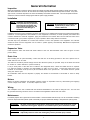
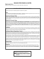
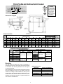
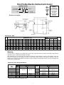
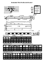
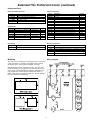
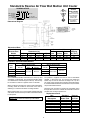
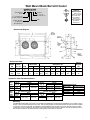
Reach-In
Unit Coolers
H-IM-77C
February, 2005
Part No. 25005601
(Replaces H-IM-77B, October, 2004)
Installation and
Operation Manual
Table of Contents
Inspection ............................................................4
Installation ...........................................................4
Expansion Valve ..................................................4
Drain Line ............................................................4
Motors..................................................................4
Wiring ..................................................................4
Maintenance ........................................................4
Replacement Parts ..............................................5
Electric Defrost Troubleshooting .........................5
Thin Profile Air Defrost Unit Cooler .....................6
Thin Profile Electric Defrost Unit Cooler .......... 7-9
Extended Thin Profile Unit Cooler ............... 10, 11
V Profile Unit Cooler ..........................................12
High Profile Unit Cooler .....................................13
Std. & Rev. Air Flow Wall Mullion Unit Cooler ...14
Wall Mount Back Bar Unit Cooler ................15, 16
Dual Aire Unit Cooler .........................................17
Twin Flow Air Defrost Unit Cooler ......................18
2
© 2005, Heatcraft Refrigeration Products LLC
3
General Information
Inspection
When the equipment is received, all items should be carefully checked against the bill of lading to make sure all crates
and cartons have been received. All units should be carefully inspected for hidden damage when received. If any damage is found, it should be reported to the carrier immediately and a claim should be filed. The unit nameplate should be
checked to make sure that the voltage agrees with the power supply available.
Installation
NOTE: Installation and maintenance are
to be performed only by qualified
personnel who are familiar with
local codes and regulations, and
experienced with this type of
equipment.
CAUTION: Sharp edges and coil surfaces are
a potential injury hazard. Avoid
contact with them.
Installation and service of this equipment should be performed only by qualified and experienced commercial refrigeration
mechanics. Correct application and installation of this equipment is necessary to obtain optimum performance and
customer satisfaction. Install all equipment, piping and electrical in accordance with local and national codes and in
conformance with good practice required for proper operation. Work safely! Prevent accidents!
The final step in any installation is to instruct the customer or user in the operation of the equipment. The customer
should be shown how the equipment can be made to operate properly and efficiently. Maintenance requirements
should be explained.
Expansion Valve
Install expansion valve and feeler bulb inside cabinet of the unit. Recommended valve sizes are given for each
product family.
Drain Line
After installing the fan panel assembly, connect the drain line to the fitting provided on the unit. A plastic hose or
metal drain line can be used.
The drain line should be pitched sharply and exit the cabinet as quickly as possible. Traps in the drain line should
be located in a warm ambient to prevent freeze-up.
If only a small portion of the drain line is located in the refrigerated area, a drain line heater will not be required.
If a drain line heater is required, use approximately 15 watts per foot of pipe. Connect the heater wire to the
terminals of the heater circuit (N and 3) at the terminal block in the junction box. The heater will then operate
during the defrost cycle.
All condensate water must be disposed of properly and should not be allowed to accumulate or cause a safety
hazard.
Motors
Motors are lifetime lubricated and thermally protected. Check an inoperative motor by disconnecting and applying
correct voltage across leads. If test fails, replace the motor.
Wiring
The nameplate on the unit is marked with the electrical characteristics to be used for wiring the unit. The unit must
be grounded. All wiring should be done in accordance with applicable national and local codes.
Maintenance
Periodically inspect unit for grease and soil accumulation. Clean with warm water and soap. Do not use cleaners containing
ammonia. Inspect the drain pan/fan panel occasionally for proper condensate drainage. Keep the drain opening clean.
WARNING:
All power must be disconnected before cleaning drain pan/fan panel. It serves as a cover
of hazardous moving parts. Operation of unit without pan in place constitutes a hazard.
WARNING:
Refrigerant can be harmful if it is inhaled. Refrigerant must be used and recovered
responsibly. Failure to follow this warning may result in personal injury or death.
4
Replacement Parts
General Information (contʼd)
Always give complete model numbers and serial numbers when ordering parts.
ELECTRIC DEFROST TROUBLESHOOTING
The electric defrost units are relatively simple and trouble-free in operation:
Timer
If the system does not go through its proper sequence , check timer operation through a defrost cycle. Check for loose
wires or terminals. Before replacing timer, check other components.
Operation of Paragon Timer
To set time of day grasp knob which is in the center of the inner (fail-safe) dial and rotate it in a counter-clockwise direction.
This will cause the outer (24 hour) dial to revolve. Line up the correct time of day on the outer dial with the time pointer.
Do not try to set the time control by grasping the other (24 hour) dial. Place pins in the outer dial at the time of day that
defrost is required.
Operation of Grasslin Timer
To set the time, turn the minute hand clockwise until the time of day (and AM or PM) on the outer dial is aligned with the
triangle marker on the inner dial. Do not rotate minute hand counter-clockwise. Move the white tab (tripper) on the
outer dial outward at each desired initiation time. Each white tab (tripper) is a 15 minute interval and provides 15 minutes
of defrost. For longer defrost duration, move additional tabs (following in time) from the initiation tab. For example, if a
45 minute defrost is to start at 7:00 AM, move the tabs outward that lie between 7:00 - 7:15, 7:15 - 7:30 and 7:30 - 7:45
on the AM side of the dial. The defrost will initiate at 7:00 AM and time terminate at 7:45 AM (if temperature termination
does not occur first).
Fan Motor
If the motor does not operate or it cycles on thermal overload, remove motor leads from terminal block and apply correct
voltage across the leads. If motor still does not operate satisfactorily, it must be replaced. Before starting the unit, rotate
fan blades to make sure they turn freely and have sufficient clearance.
Fan Delay & Defrost Termination Control
This control is a single pole double throw switch. The red lead wire is wired to common. The black wire is wired in series
with the fan motors. The brown wire is wired in series with the defrost termination solenoid in the timer. The brown and
red contacts close and the black and red contacts open when the temperature is above 55ºF. The black and red contacts
close and the brown and red contacts open when the temperature is below 35ºF.
On initial “pull down” of a warm box the fan will not start until the coil temperature reaches approximately 35ºF. If the box
is still comparatively warm (60ºF) when the fan starts, then blowing this warm air over the coil may cause it to warm up
to 55ºF and thus stop the fan. Therefore, the fan may recycle on initial “pull down.” This control cannot be adjusted.
If the fan motor fails to start when the control is below 35ºF, disconnect the fan motor leads and check the motor as
described for fan motors. Also check whether current is being supplied at “N” and “4” from the timer. The fan delay
control must be below 35ºF when checking for a closed circuit.
Defrost Heater
If unit shows very little or no defrosting and does not heat, disconnect heater and check to find if it is burned out. To test,
apply correct voltage across heater or use continuity flashlight battery tester.
Drain Pan
If drain pan has an ice build-up, drain line may be frozen. The drain line should be pitched sharply and exit cabinet
as quickly as possible. Sometimes location and ambient at the drain outside of cabinet may cause freeze-up. A drain
line heater may be required to correct the freeze-up. Any traps in the drain line must be located in a warm ambient.
NOTE: After correcting faulty condition it is
essential that the coil and unit be free of
ice before placing unit back on automatic
operation.
5
Thin Profile Air Defrost Unit Cooler
Thin Profile
Unit Cooler
NOMENCLATURE
TA (K) 17 B G
K = Coated Coil
(Optional)
FOR FOOD
SERVICE
INSTALLATIONS
. . . seal any joint
between unit cooler
and cooler liner
with a sealant
listed by the
National Sanitation
Foundation,
Standard 51
Vintage
A = 115-1-60
B = 208/230-1-60
Size
Dimensional Diagram
Dimensional Data
Model
No.
10
13
17
23
30
43
55
A
14 5/8
18 5/8
22 1/8
29 3/4
38 1/8
51 1/2
51 1/2
B
C
14
14
15
15
15
15
15
/16
15
/16
15
/16
15
/16
15
/16
15
/16
15
/16
15
D
13 1/2
13 1/2
14 1/2
14 1/2
14 1/2
14 1/2
14 1/2
E
10 1/2
10 1/8
11 1/8
13
13
13
13
Dimensions (in.)
F
H
J
11 3/8
10 1/4
12
20 7/8
29 3/4
48 3/4
49
4 1/2
4 1/2
4 1/2
4 1/2
4 1/2
4 1/2
6 3/4
8 7/8
8 3/8
9 3/8
10 3/4
10 3/4
10 3/4
10 3/4
Expansion Valve Recommendations
25°F Sat. Suction Temp.
Model
BTUH @
R-22
Size
10°F TD
Alco
Sporlan
10
1000
13
1300
17
1700
HFS-1/4HC
EFV-1/5C
23
2300
30
3000
43*
4300
HFES-1/2HC EFVE-1/2C
55*
5500
* Size 43 and 55 use external equalized valves.
K
2 1/2
9 1/2
11 1/4
10 1/4
9 3/4
13 1/4
11
L
/16
15
/16
15
/16
15
/16
15
/16
15
/16
15
/16
15
M
4 3/8
4 3/8
4 3/8
4 3/8
4 3/8
4 3/8
4 3/8
W
16 1/2
20 1/2
24
31 5/8
40
53 3/8
53 3/8
Connections (in.)
Approx.
Coil
Shipping
Inlet Suction Drain Wt. (lbs.)
/8 OD
/8 OD
3
/8 OD
3
/8 OD
3
/8 OD
1
/2 OD
1
/2 OD
/8 ID
/8 ID
1
/2 ID
1
/2 ID
1
/2 ID
5
/8 ID
5
/8 ID
3
1
3
3
1
20°F Sat. Suction Temp.
BTUH @
R-22
15°F TD
Alco
Sporlan
1500
EFV-1/5C
1950
HFS-1/4HC
2550
3450
EFV-1/3C
4500
HFS-1/2HC
6450
HFES-1HC
EFVE-1C
8250
Mounting
The thin profile air defrost unit cooler is designed for
mounting from the top of the cooler. Drill holes for screws
in accordance with mounting dimensions A and B given
in Dimensional Data.
Replacement Parts
Description
115V Motor
208/230V Motor
Fan Blade
Fan Guard
Motor Mount
After unpacking the unit, remove the fan panel and arrange
the rear brackets as shown in the drawing. Insert the
screws for mounting the rear brackets into the top of the
cooler cabinet. Slip the rear brackets, attached to the unit,
between the screw head and cabinet and secure in place.
Install the front mounting screws. For proper drainage, the
unit should be installed level.
6
/2 OD
/2 OD
1
/2 OD
1
/2 OD
1
/2 OD
1
/2 OD
1
/2 OD
3
All Sizes Part Number
25300701
25300801
5101B
5054D
91179001
14
17
21
28
33
44
53
Thin Profile Electric Defrost Unit Cooler
NOMENCLATURE
Thin Profile
Electric Defrost
TL
12
A
G
Size
FOR FOOD
SERVICE
INSTALLATIONS
. . . seal any joint
between unit cooler
and cooler liner
with a sealant
listed by the
National Sanitation
Foundation,
Standard 51
Vintage
A = 115-1-60
B = 208/230-1-60
Dimensional Diagram
Dimensional Data
Size A
09
12
16
21
28
35
53
B
145/8 14
185/8 14
221/8 15
221/8 161/2
293/4 15
353/4 161/2
461/2 161/2
C
/16
15
/16
15
/16
15
/16
15
/16
15/16
11/8
15
D
131/2
131/2
141/2
161/2
141/2
161/2
161/2
E
101/2
101/8
111/8
141/2
13
141/2
141/2
Dimensions (In.)
F
H
J
K
113/8
101/4
12
187/8
203/4
331/4
44
41/2
41/2
41/2
63/4
63/4
63/4
63/4
87/8
21/2
3
8 /8
91/2
3
9 /8 111/4
117/8 171/4
93/4
97/8
5
11 /8 183/8
115/8 303/8
L
/16
15
/16
15
/16
15
/16
15
/16
15/16
11/2
15
M
43/8
43/8
43/8
43/8
43/8
6”
6”
N
51/8
51/8
W
161/2
201/2
24
24
315/8
383/8
491/8
Connections (In.) Approx.
Coil
Ship Wt.
Inlet Suction Drain (Lbs.)
/8
/8
3
/8
3
/8
3
/8
1
/2
1
/2
3
3
OD
OD
OD
OD
OD
OD
OD
/8
/2
1
/2
1
/2
1
/2
5
/8
7
/8
3
1
ID
ID
ID
ID
ID
ID
ID
/2
/2
1
/2
1
/2
1
/2
1
/2
1
/2
1
1
OD
OD
OD
OD
OD
OD
OD
14
19
23
24
27
38
53
Mounting
This unit cooler is designed for mounting from the top of the cooler. Drill holes for screws in accordance with mounting
dimensions given in Dimensional Diagram and Data.
After unpacking the unit, remove the fan panel and arrange the rear brackets as shown in the drawing. Insert the
screws for mounting the rear brackets into the top of the cooler cabinet. Slip the rear brackets, attached to the unit,
between the screw head and cabinet and secure in place. Install the front mounting screws. For proper drainage, the
unit should be installed level.
Expansion Valve Recommendations
Model
Size
09
12
16
21
28
35*
53*
BTUH
10° TD
900
1200
1600
2100
2800
3500
5300
-10°F. Suction 10° TD
R-404
Alco
Sporlan
HFS1/8SZ
EFS1/8Z
HFS /4SZ
HFES1/4SZ
HFES1/2SZ
EFS /6Z
EFSE1/4Z
EFSE1/2Z
1
BTUH
15° TD
1350
1800
2400
3150
4200
5250
7950
1
*Sizes 35 and 53 use external equalized valves.
7
-15°F. Suction 15° TD
R-404A
Alco
Sporlan
HFS1/8SZ
EFS1/8Z
HFS1/4SZ
HFS1/2SZ
HFES1/2SZ
HFES1SZ
EFS1/6Z
EFS1/4Z
EFSE1/2Z
EFSE1Z
Sequence of Operation
2. The compressor now starts.
3. Then fan motors remain off because the fan delay thermostat
is open. This prevents warm air from being blown into the
refrigerated space.
4. The evaporator coil cools down approaching operating
temperature. Superheated gas only passes to the compressor.
Step “A” - Normal Refrigeration Cycle
1. Power is supplied to N and 4 terminals by the timer.
2. The fan delay and defrost termination thermostat is closed in
the fan delay position and open in the defrost termination position.
3. The defrost heater is off.
4. The compressor operates in accordance with the demands of
the refrigeration system temperature and/or pressure controls.
5. The unit cooler fan operates continually.
6. Frost builds up slowly on the evaporator.
Step “D” - Return to Normal
Refrigeration Operation
1. When the coil temperature reaches 35ºF, the fan control switch
closes. This allows current to flow to the fan motor and the unit is
now back in operation as in Step “A.”
Step “B” - Defrost Cycle
1. Defrosting of the evaporator is started automatically by the
timer at predetermined times - typical settings of the timer would
be 1 to 3 defrost periods per 24 hours.
2. The timer mechanically opens switch “A” which breaks the
circuit to the compressor and evaporator fan motors, thereby
shutting them off, and closes switch “B,” thereby permitting current
to flow to the heater.
3. The heater recessed in slots, gives up heat directly to the fins
of the evaporator. This heat raises coil and refrigerant temperature
to 32ºF causing the frost to melt.
4. Frost on the evaporator is melted and defrost water drips into
the heated drain pan and flows down the drain.
5. When frost has completely melted from the coil, the coil starts
to warm up beyond 32ºF.
IMPORTANT
1. On initial “pull down” of a warm box, the fan will not start
until coil temperature reaches approximately 35ºF. If box is still
comparatively warm (60ºF) when the fan starts, then blowing this
warm air over the coil may cause it to warm up to 55ºF and thus
stop the fan. Therefore, fan may recycle several times on initial
“pull down.”
2. The timer has an adjustable fail-safe feature which will return
the system to the refrigeration cycle at the end of a predetermined
time (factory set at 24 minutes) if automatic control devices fail.
3. Frequent defrost periods are not necessary! The determining
factor for number of defrosts per day is the frost load. When frost
“build-up” results in a loss of refrigeration capacity, then a defrost
is required. One to three defrosts per day are recommended.
4. A low temperature thermostatic expansion valve with pressure
limiting feature is desirable for use with these units. Such a valve
prevents feeding of refrigerant to the coil during the defrost cycle.
Step “C” - Coil Re-Cooling Cycle
1. When the coil warms up to 55ºF, the defrost termination
thermostat closes which allows the current to flow to the solenoid
in the timer, which then energizes and trips the timer switch back
to its normal position (switch “A” closed, switch “B” open). The fan
delay portion of this thermostat is now open.
Typical Wiring Diagram for Thin Profile
Electric Defrost Unit Cooler
Model
Size
09
12
16
21
28
35
53
No. of
Motors
1
2
2
1
3
2
3
Motor
Amps.
A*
B*
0.8
0.4
1.6
0.8
1.6
0.8
1.0
0.5
1.2
1.0
1.5
Heater
Amps.
A*
B*
4.13
2.07
5.22
2.61
6.09
3.04
9.57
4.78
5.7
7.0
8.5
1. Use copper conductors only.
2. Unit must be grounded.
3. Timer-Paragon Model 8145-20 may be factory supplied,
field installed, or field supplied and installed.
4. Fan delay and defrost termination - Red to N, Brown to X,
Black to F. Fans will not operate until thermostat resets.
5. Heater limit: Red to N, White to H omitted on model 28;
heater is connected directly to N.
6. *Indicates electrical code: A=115/60/1, B=208-230/60/1.
Replacement Parts
Part
Description
Motor
Fan Blade
Fan Guard
Heater
Heater Clip
Defrost Control
Mount
09
115 Volt
12
16
21
09
12
16
208-230 Volt
21
28
25300701 25300701 25300701 25303201 25300801 25300801 25300801 25303301 25300801
5101B
5101B
5101B 23100201
5101B
5101B
5101B
23100201
5101B
5054D
5054D
5054D
H50328
5054D
5054D
5054D
H50328
5054D
4539N
4540N
4541N
4545N
4542N
4543N
4544N
4546N
H50097
5543J
5543J
5543J
5543J
5543J
5543J
5543J
5543J
H50039
5709L
5709L
5709L
5709L
5709L
5709L
5709L
5709L
5709L
91179001 91179001 91179001 23101401 91179001 91179001 91179001 23101401 91179001
8
35
25303301
23100201
H50328
24700701
5543J
5709L
23101401
53
25303301
23100201
H50328
24700702
5543J
5709L
23101401
Typical System Wiring Diagram
with Thin Profile Electric Defrost Unit Cooler
9
Extended Thin Profile Unit Cooler
Extended
Thin Profile
Unit Cooler
NOMENCLATURE
LT A 053 A A
A = Air Defrost
L = Electric Defrost
Size
FOR FOOD
SERVICE
INSTALLATIONS
. . . seal any joint
between unit cooler
and cooler liner
with a sealant
listed by the
National Sanitation
Foundation,
Standard 51
Vintage
A = 115-1-60
B = 208/230-1-60
Dimensional Diagram
Dimensional Data
Air
Electric Number
Defrost Defrost
of
A
LTA
LTL
Fans Inches
053
046
2
49 3/8
079
068
3
69 1/8
102
093
4
88 7/8
134
115
5
108 5/8
172
133
6
128 3/8
mm
1254
1756
2257
2759
3261
Dimensions (Inches / mm)
B
C
Inches
mm
Inches
mm
40 7/8
1038
----60 5/8
1540
----80 3/8
2042
40 7/8
1038
100 1/8
2543
40 7/8
1038
119 7/8
3045
40 7/8
1038
Model
Size
LTA 053
LTA 079
LTA 102
LTA 134
LTA 172
D
mm
--------1003
Connections- Electric Defrost
Connections- Air Defrost
Number
of
Fans
2
3
4
5
6
Inches
--------39 1/2
Connections (Inches)
Net
Coil
External
Weight
Inlet
Suction Equalizer Drain
(Lbs.)
1/2 OD
5/8 ID
1/4
3/4 MPT
48
1/2 OD
5/8 ID
1/4
3/4 MPT
69
1/2 OD
7/8 ID
1/4
3/4 MPT
85
1/2 OD
7/8 ID
1/4
3/4 MPT
108
1/2 OD 1 1/8 ID
1/4
3/4 MPT
124
Model
Size
LTL 046
LTL 068
LTL 093
LTL 115
LTL 133
Number
of
Fans
2
3
4
5
6
Coil
Inlet
1/2 OD
1/2 OD
1/2 OD
1/2 OD
1/2 OD
Connections (Inches)
Net
External
Weight
Suction Equalizer Drain
(Lbs.)
5/8 ID
1/4
3/4 MPT
48
5/8 ID
1/4
3/4 MPT
69
7/8 ID
1/4
3/4 MPT
85
7/8 ID
1/4
3/4 MPT
108
1 1/8 ID
1/4
3/4 MPT
124
Nozzle Selection- Air Defrost
Nozzle Selection- Electric Defrost
Number Air Distributor Tube Number
of
Defrost
OD
Length
of
Fans
LTA (Inches) (Inches) Circuits R404A
2
053
3/16
21 1/2
2
L-1/2
3
079
3/16
21 1/2
2
L-1/2
4
102
3/16
21 1/2
4
L-3/4
5
134
3/16
21 1/2
4
L-1
6
172
3/16
21 1/2
5
L-1 1/2
Number Electric Distributor Tube Number Low Temp.
Medium Temp.
-30ºF to 0ºF SST +10ºF to +25ºF SST
of
Defrost
OD
Length
of
Fans
LTL (Inches) (Inches) Circuits R404A R22
R404A
R22
2
046
3/16
21 1/2
3
L-3/4
L-1/2
L-1/2
L-1/3
3
068
3/16
21 1/2
3
L-3/4
L-1/2
L-3/4
L-1/2
4
093
3/16
21 1/2
5
L-1
L-3/4
L-1
L-3/4
5
115
3/16
21 1/2
5
L-1 1/2
L-1
L-1
L-3/4
6
133
3/16
21 1/2
5
L-1 1/2
L-1
L-1 1/2
L-1
R22
L-1/3
L-1/3
L-1/2
L-3/4
L-1
10
Extended Thin Profile Unit Cooler (continued)
Replacement Parts
Motor / Fan Blade / Fan Guard
Part #
25315501
25315601
22919001
23105001
23105101
Cabinet Components
Part #
40970201
40970301
40970401
40970501
40970601
46834201
46834301
46844201
46844301
40931201
40931301
40930901
40931001
40931401
40931101
40931601
Description
Motor 115/1/60 Shaded Pole
Motor 208-230/1/60 Shaded Pole
Fan Blade 10”
Fan Guard - Wire
Motor Mount
Defrost Heater
Part #
24723002
24723003
24723004
24723005
24723006
23305501
Description
Defrost Heater 1100W 230V
Defrost Heater 1650W 230V
Defrost Heater 2200W 230V
Defrost Heater 2750W 230V
Defrost Heater 3300W 230V
Heater Clip
Voltage
208-230/1/60
208-230/1/60
208-230/1/60
208-230/1/60
208-230/1/60
N/A
No. Fans
2
3
4
5
6
3-7
No. Fans
2
3
4
5
6
2, 4, 5
3, 5, 6
2, 4, 5
3, 6
N/A
N/A
N/A
N/A
N/A
N/A
N/A
Electrical Components
Drain Fitting
Part #
26925101
Description
Drain Pan
Drain Pan
Drain Pan
Drain Pan
Drain Pan
Fan Panel - 2 Fan
Fan Panel - 3 Fan
Beacon Fan Panel - 2 Fan
Beacon Fan Panel - 3 Fan
Panel - Side Right (Piping End)
Panel - Front Access Right (Piping End)
Panel - Side Left (Electrical End)
Panel - Front Access Left (Electrical End)
Panel - Back Right (Piping End)
Panel - Back Left (Electrical End)
Panel - Beacon Access
Part #
4145W
5709L
5709L
4131Y
5708L
Description
Drain Fitting Assembly
Mounting
Description
Terminal Strip - Electric Defrost Models
Defrost Termination Thermostat - sealed bimetal type
Fan Delay Thermostat - sealed bimetal type
Room Thermostat
Heater Limit Thermostat - sealed bimetal type
Wiring Diagram
This unit cooler is designed for mounting from the top of the
cooler. Drill holes for screws in accordance with mounting
dimensions given in Dimensional Diagram and Data.
After unpacking the unit, arrange the unit 7 1/2” from wall.
Insert the screws for mounting the rear brackets into the top
of the cooler cabinet. Slip the rear brackets, attached to the
unit, between the screw head and cabinet and secure in
place. Install the front mounting screws. For proper drainage,
the unit should be installed level.
Coils
Coils
Coils
11
V Profile Unit Cooler
NOMENCLATURE
VA (K) 08 A G
V Profile
Unit Cooler
Vintage
A = 115-1-60
B = 208/230-1-60
K = Coated Coil
(Optional)
Size
Dimensional Diagram
Dimensional Data
V
Profile
Model
A
B
C
Dimensions (In.)
D
E
F
H
J
K
W
3
7
1
1
Connections (In.)
Coil
Inlet Suction Drain
Approx.
Ship Wt.
(Lbs.)
06
4 /16 13 /4 4 /16
-
-
3 /8
6 /8
5 /4
8 /8
12 1/2
3
/8 OD
3
/8 ID
1
/2 OD
9
08
4 /16 13 /4 4 /16
-
-
3
3 /8
7
6 /8
1
5 /4
1
8 /8
1
12 /4
3
/8 OD
3
/8 ID
1
/2 OD
9
12
4 /2
18 /4 5 /16
-
-
3
3 /8
8
4 /8
1
8 /8
18
3
/8 OD
3
/8 ID
1
/2 OD
14
17
5 1/4 14 3/4 5 1/4
9
2 1/ 2
4
9 3/ 4
10 1/2
14
3
/8 OD
3
/8 ID
1
/2 OD
11
5
5
1
1
1
3
5
5
5
7
6
13
Expansion Valve Recommendations
V
Profile
Model
06
08
12
17
/16
25°F. Evaporating Temp.
20°F. Evaporating Temp.
BTUH @
R-22
BTUH @
R-22
10°F. TD
Alco
Sporlan 15°F. TD
Alco
Sporlan
600
900
800
HFS 1/4 HC EFV 1/5 C
1200
HFS 1/4 HC
EFV 1/5 C
1200
1800
1700
2550
Mounting
Replacement Parts
Description
115V Motor
208/230V Motor
Fan Blade
Fan Guard
Motor Mount
V Profile Models
06, 08, 12
17
25300701
25300801
5101B
5054D
91179001
FOR FOOD
SERVICE
INSTALLATIONS
. . . seal any joint
between unit cooler
and cooler liner
with a sealant
listed by the
National Sanitation
Foundation,
Standard 51
25303201
25303301
23100201
H50328
23101401
The V profile unit cooler is designed for mounting from the top or
the back wall of the cooler. Drill holes for screws in accordance
with mounting dimensions given in Dimensional Data.
After unpacking the unit, secure top of unit to ceiling or back wall
and arrange the rear brackets as shown in the drawing. Mount the
rear brackets to wall, if applicable, to the installation.
For proper drainage, the unit should be installed level.
12
High Profile Unit Cooler
High Profile
Unit Cooler
NOMENCLATURE
C (K) 43 B G
K = Coated Coil
(Optional)
FOR FOOD
SERVICE
INSTALLATIONS
. . . seal any joint
between unit cooler
and cooler liner
with a sealant
listed by the
National Sanitation
Foundation,
Standard 51
Vintage
A = 115-1-60
B = 208/230-1-60
Size
Dimensional Diagram
Dimensional Data
Model
No.
13
17
23
30
43
A
12 5/8
15 5/8
21 5/8
26 1/8
36 5/16
Dimensions (In.)
B
C
D
12 3/8
12 3/8
12 3/8
12 3/8
-
11 7/16
14 7/16
21 1/16
25 13/16
-
1 3/8
1 3/8
7
/8
1
-
W
14 1/4
17 1/4
22 3/4
27 3/4
38
Expansion Valve Recommendations
25°F Sat. Suction Temp.
Model
BTUH @
R-22
Size
10°F TD
Alco
Sporlan
13
1300
17
1700
HFS-1/4HC
EFV-1/5C
23
2300
30
3000
43*
4300
HFES-1/2HC EFVE-1/2C
* Size 43 uses external equalized valve.
Connections (In.)
Coil
Inlet
Suction
Drain
/8
/8
3
/8
3
/8
1
/2
3
3
OD
OD
OD
OD
OD
/8
/2
1
/2
1
/2
1
/2
3
1
ID
ID
ID
ID
ID
/2
/2
1
/2
1
/2
1
/2
1
1
OD
OD
OD
OD
OD
20°F Sat. Suction Temp.
BTUH @
R-22
15°F TD
Alco
1950
2550
HFS-1/4HC
3450
4500
HFS-1/2HC
6450
HFES-1HC
Approx.
Ship Wt.
(Lbs.)
16
17
22
27
40
Sporlan
EFV-1/5C
EFV-1/3C
EFVE-1C
Replacement Parts
Mounting
Using dimensions given in Dimensional Diagram and Data,
install mounting screws for rear hangers and slide hanger
slots onto screws before tightening. Open cabinet and install
screws through top, front mounting holes to ceiling of box.
13
Description
115V Motor
208/230V Motor
Fan Blade
Fan Guard
Motor Mount
All Sizes Part Number
25303201
25303301
23100201
H50328
23101401
Standard & Reverse Air Flow Wall Mullion Unit Cooler
NOMENCLATURE
FOR FOOD
SERVICE
INSTALLATIONS
. . . seal any joint
between unit cooler
and cooler liner
with a sealant
listed by the
National Sanitation
Foundation,
Standard 51
XXX K 13 A G
KM = Standard
Air Flow
RAM=Reverse
Air Flow
K = Coated Coil
Size
Vintage
A = 115-1-60
B = 208/230-1-60
Dimensional Diagram
Dimensional Data
Standard or
Reverse Flow
Models
13
17
23
H
17 3/4
19 3/4
19 3/4
Dimensions (In.)
L
M
16 7/8
16 7/8
23 1/4
W
12 1/4
14 1/4
14 1/4
15 5/8
15 5/8
22
Connections (In.)
Coil
Inlet
Suction Drain
/8 OD
/8 OD
3
/8 OD
/8 OD
/8 OD
1
/2 OD
/8 OD
/8 OD
5
/8 OD
3
3
5
3
3
5
Approx.
Shipping
Wt. (Lbs.)
19
20
28
Expansion Valve Recommendations
Model
Size
13
17
23
25°F Sat. Suction Temp.
BTUH @
R-22
10°F TD
Alco
Sporlan
1300
1700
HFS-1/4HC
EFV-1/5C
2300
20°F Sat. Suction Temp.
BTUH @
R-22
15°F TD
Alco
Sporlan
1950
EFV-1/5C
2550
HFS-1/4HC
3450
EFV-1/3C
Mounting
A top barrier is supplied and must be used if combustible
material is above the unit. On reverse flow models the
barrier may be used to direct the air straight out or up at a
45° angle. Holes and slots are provided to adjust the barrier.
If noncombustible material is used above the unit, the barrier
may be discarded if desired.
The standard flow mullion unit draws air in at the top and
discharges out the bottom. The reverse flow mullion draws
air in at the bottom and discharges out the top. The unit may
be mounted in a mullion or against a back or side wall.
When mounting to the mullion of under counter refrigerators,
mounting holes are located on both ends of the unit for
attaching to “customer furnished” mounting brackets.
Knockouts are provided for bringing the refrigerant piping
through either end of the cabinet. An electrical knockout is
provided into an internal junction box.
When wall mounted, four “L” type brackets and eight stainless
steel sheet metal screws are provided to attach the brackets
to side panels.
Replacement Parts
Part
Standard
Description
Down Flow
115V Motor
25300701
208/230V Motor
25300801
Fan Blade
5102C
Fan Guard (13-17)
5076E
Fan Guard (23)
5077E
Motor Mount
91179001
Drain Pan (13-17)
74422002
Drain Pan (23)
74436002
IMPORTANT: A minimum of 2 inches must be provided
between the top of the unit and the top of the cabinet.
14
Reverse
Up Flow
25300701
25300801
5117C
5076E
5077E
91179001
74422002
74436002
Wall Mount Back Bar Unit Cooler
Back Bar Unit
Cooler
NOMENCLATURE
BB L S 10 A G
FOR FOOD
SERVICE
INSTALLATIONS
. . . seal any joint
between unit cooler
and cooler liner
with a sealant
listed by the
National Sanitation
Foundation,
Standard 51
Revision
A = 115-1-60
B = 208/230-1-60
L = Low Temp Unit
M = Med. Temp Unit
Size
Blank = Std. Unit
S = Slave Unit
M = Master Unit
Dimensional Diagram
Dimensional Data
Model
BB
L10
M11
L15
M16
BTUH
10°F TD
1,000
1,100
1,500
1,600
CFM
90
90
180
180
Motor Data
Qty.
HP
1
1/150
1
1/150
2
1/150
2
1/150
W
193/4
193/4
261/4
261/4
A
191/8
191/8
255/8
255/8
Dimensions (In.)
B
C
D
18
171/2
71/16
18
171/2
71/16
241/2
24
413/16
241/2
24
413/16
NOTE: All units have 3/8 O.D. suction, 1/2 O.D. sweat inlet connection and 1/2 O.D. drain.
E
85/8
85/8
F
165/8
165/8
231/8
231/8
Approx.
Ship Wt.
(Lbs.)
17
16
20
19
Expansion Valve Recommendations
Low
Temp
Model
BBL10
BBL15
-10°F Sat. Suction Temp.
BTUH @
R-404A
10°F TD
Alco
Sporlan
1000
HFS-1/8SZ
EFS-1/8Z
1500
-15°F Sat. Suction Temp.
BTUH @
R-404A
15°F TD
Alco
Sporlan
1500
HFS-1/8SZ
EFS-1/8Z
2250
HFS-1/4SZ
EFS-1/6Z
Med
25°F Sat. Suction Temp.
Temp
BTUH @
R-22
Model 10°F TD
Alco
Sporlan
BBM11
1100
HFS-1/4HC
EFV-1/5C
BBM16
1600
20°F Sat. Suction Temp.
BTUH @
R-22
15°F TD
Alco
Sporlan
1870
HFS-1/4HC
EFV-1/5C
2720
Mounting
Replacement Parts
Description
115V Motor
208/230V Motor
Fan Blade
Fan Guard
Motor Mount
All Sizes Part No.
25300701
25300801
5101B
5054D
91179001
The Wall Mount Back Bar Unit Cooler is a low height unit designed for undercounter applications. Air is drawn in at the
bottom of the unit and discharged out the front. Two mounting angles are included with the unit and should be installed
to space the unit 3/4” off the wall. Air deflector(s) are included and can be mounted over the top half of the fan guard
to direct the air up. The deflector may be left off if total horizontal air movement is desired. If used, the deflector can be
field formed to direct the air where needed. Locating holes and screws are provided.
15
Air Defrost Wiring, Model BBM
Electric Defrost Wiring, Model BBL
16
Dual Aire Unit Cooler
NOMENCLATURE
U K 009
0
Dimensional Diagram
B
Design
Revision
U - Dual Aire
K - Coated Coil
0 = 115/60/1
1 = 208-230/60/1
A = 110/50/1
C = 220/50/1
Size
FOR FOOD
SERVICE
INSTALLATIONS
. . . seal any joint
between unit cooler
and cooler liner
with a sealant
listed by the
National Sanitation
Foundation,
Standard 51
Recognized Component
Underwriterʼs Lab., Inc.
Dimensional Data
Dual Aire
Models
H
Dimensions (In.)
W
D
A
B
Connections (In.)
Approx.
Coil
Ship Wt.
Inlet Suction Drain (Lbs.)
C
009
1
8 /2
11 /2 8 /8
6
4
3 1/ 2
1
/2 FN
3
/8 ID
1
/2 OD
8
012
1
8 /2
17 /2 8 /8
12
4
1
9 /2
1
/2 FN
3
/8 ID
1
/2 OD
10
015
9 /2
17 /2 10 /8
12
4
9 /2
1
/2 FN
3
/8 ID
1
/2 OD
12
1
1
7
1
7
1
7
1
Expansion Valve Recommendations
Model
Size
009
012
015
25°F Sat. Suction Temp.
BTUH @
R-22
10°F TD
Alco
Sporlan
850
1150
HFS-1/4HC EFV-1/5C
1500
20°F Sat. Suction Temp.
BTUH @
R-22
15°F TD
Alco
Sporlan
1275
1725
HFS-1/4HC EFV-1/5C
2250
Mounting
1. Drill holes in ceiling or backwall and insert #10 screws
to within 1/16” of surface.
2. Attach expansion valve drip pan to drain pan of unit.
3. Check all screws for tightness.
4. Hang unit using keyhole slots, adjusting mounting screws
as necessary. Tighten screws from inside of cabinet.
Remove drain pan to reach screws.
Replacement Parts
Description
Drain Pan
Valve Drip Pan
Fan Panel
Motor (115/1)
(208-230/1)
Top Panel
Fan (115/1)
(208-230/1)
Motor Mount
Replacement Part for Size:
009
012
015
66974002
66982001
66970001
5025S
5026T
66973001
5124A
92726001
91746001
66958002
66982001
66956001
5025S
5026T
66957001
5126A
92726002
91746001
66980002
66982001
66976001
5026S
5026T
66979001
5127A
5127A
91746001
*Optionally available are molded harness for motor
connection in the following lengths:
30” (4318K001)
48” (4318K002)
WARNING:
All power must be disconnected before cleaning drain pan. It also serves as cover of hazardous moving parts,
and operation of unit without pan in place constitutes a hazard.
17
Twin Flow Air Defrost Unit Cooler
NOMENCLATURE
BTO K 13 A G
Twin Flow
FOR FOOD
SERVICE
INSTALLATIONS
. . . seal any joint
between unit cooler
and cooler liner
with a sealant
listed by the
National Sanitation
Foundation,
Standard 51
Vintage
A = 115-1-60
B = 208/230-1-60
K = Coated coil
Size
Dimensional Diagram
Dimensional Data
Twin
Flow
Model
09
13
18
25
35
45
55
A
161/8
161/8
161/8
181/8
181/8
211/8
211/8
B
191/8
191/8
191/8
261/8
261/8
291/8
291/8
C
79/16
79/16
79/16
111/16
111/16
83/16
83/16
D
4
4
4
4
4
73/4
73/4
Dimensions (In.)
E
F
G
25/16
99/16
23/4
25/16
99/16
23/4
25/16
99/16
23/4
25/16
131/16
23/4
25/16
131/16
23/4
37/16
195/8
31/2
37/16
105/8
31/2
H
47/8
47/8
53/4
63/4
63/4
91/4
81/2
J
41/2
41/2
41/2
51/2
51/2
8
8
NOTE: All units have 1/2 I.D. suction, 1/2 O.D. sweat inlet connection and 1/2 O.D. drain.
K
85/8
85/8
85/8
121/8
121/8
135/8
135/8
L
21/2
21/2
21/2
31/2
31/2
515/16
515/16
M
25/8
25/8
25/8
25/8
25/8
41/4
41/4
Fan
Qty. Dia.
1
51/2”
2
51/2”
1
8”
2
8”
2
8”
2
8”
1
12”
Approx.
Ship Wt.
(Lbs.)
12
14
15
23
24
34
34
Expansion Valve Recommendations
Model
Size
09
13
18
25*
35*
45*
55*
25°F. Sat. Suction Temp.
20°F.
BTUH @
R-22
BTUH @
10°F. TD
Alco
Sporlan 15°F. TD
900
1350
1300
HF S1/4 HC EFV 1/5 C
1950
1800
2700
2500
3750
HFES- 1/4 HC EFVE- 1/3C
3500
5250
4500
6750
HFES- 1/2 HC EFVE- 1/2C
5500
8250
Sat. Suction Temp.
R-22
Alco
Sporlan
HFS-1/4 HC
EFV-1/5 C
HFES- 1/2 HC
EHFE- 1/3 C
HFES-1 HC
EFVE-1 C
*Sizes 25, 35, 45 & 55 use external equalized valves.
Replacement Parts
Twin Coil
Models
09
13
18
25
35
45
55
Motor
115V
208/230V
25300701 25300801
25300701 25300801
25303201 25303301
25303201 25303301
25303201 25303301
25303201 25303301
5036S
5036T
Fan
Blade
5101B
5101B
23100201
23100201
23100201
23100201
5110E
Fan
Guard
5054D
5054D
H50328
H50328
H50328
H50328
5055F
18
Motor
Mount
91179001
91179001
23101401
23101401
23101401
23101401
40003001
Mounting
The Twin Flow unit cooler is
designed for mounting from the
top of the cooler. Drill holes for bolts
or screws according to dimensions
given in Dimensional Diagram and
Data. Double keyhole slots are
provided so screws may be installed
first and then the unit positioned
over the screw head and slid left or
right, then tighten screws to secure
the unit.
19
Since product improvement is a continuing effort,
we reserve the right to make changes in specifications without notice.
Heatcraft Refrigeration Products LLC
2175 W. Park Place Blvd. • Stone Mountain, GA 30087
(770) 465-5600 • Fax: (770) 465-5990 • www.heatcraftrpd.com